Note : Les descriptions sont présentées dans la langue officielle dans laquelle elles ont été soumises.
CA 02338583 2001-O1-25
WO 00/08965 PCTNS99/18046
PATIO UMBRELLA WITH RADIANT HEATER
DESCRIPTION
Technical Field
The present invention is a patio umbrella that includes a fuel-burning radiant
heater and a dining table.
It frequently happens that outdoor temperature ranges from comfortably
warm at mid-day to chilly in the evenings. The comfortable mid-day
temperatures
are an incentive for restaurant owners to provide facilities for outdoor patio
dining.
However, construction of such facilities is predicated on their efficient use,
which
is somewhat marginal unless steps are taken to insure the comfort of the
customers
throughout a substantial portion of the entire day, including the cooler
hours.
To this end, outdoor patios are often provided with radiant heaters that burn
natural gas or propane gas. Heaters of this type are available from a number
of
manufacturers. A typical heater of this type is approximately 93 inches tall.
The
combustion chamber is supported by a hollow column that extends upward from
the
floor, and a reflector in the shape of an inverted dish is located above the
I 5 combustion chamber for the purpose of reflecting radiant heat downward
that would
otherwise travel skyward.
Ordinarily, when radiant heaters are installed on a patio, they are placed
between the tables where they become an obstacle for the service employees and
for
the customers alike. To provide adequate space for passage around the heaters,
the
tables must be more widely spaced, thereby rendering the patio less efficient.
Because the outdoor daytime temperature may be quite warm and because
the patio may be subjected to direct sunshine, it is desirable to protect the
customers
from the direct sunshine by providing a large umbrella, often called a beach
umbrella
CA 02338583 2001-O1-25
WO 00/08965 PCT/US99/18046
2
or patio umbrella. Such umbrellas typically measure 6 to 8 feet across, and
they are
not generally practical where high wind speeds prevail.
The present invention is one solution to the many problems that must be
considered in combining a radiant heater with a large umbrella. It does not
appear
that such a combination has successfully been made prior to the present
invention.
The Prior Art
In U. S. Patent No. 3,295,473 issued January 3, 1967, Wentworth describes
a table mounted on the vertical shaft of a large umbrella, but there is no
heater.
Likewise, in U.S. Patent No. 3,624,732 issued November 30, 1971, Bowden also
shows a vertically-adjustable table mounted on the vertical shaft of a large
umbrella.
Again, no suggestion of supplying heat is given.
In U.S. Patent No. 3,739,972 issued June 19, 1973, Holland describes a
hand-carried rain umbrella in which the ribs of the umbrella incorporate
electric
heating elements that are operated by batteries within the shaft of the
umbrella.
Because this umbrella does not use a heater in which combustion occurs, the
problems inherent in this umbrella are different from those encountered in the
present invention.
In U.S. Patent No. 3,625,235 issued December 7, 1971 to Gorgichuk, there
is shown a spherical shelter in which a stove sits on the floor, and a
stovepipe
extends vertically upward and through a hole at the top of the structure.
Likewise,
in U. S. Patent No. 4,844,108 issued July 4, 1989, Rohrer shows a tent
containing
a stove. The stove is located near the floor, and the tent is supported by a
hollow
vertical central column that serves as a chimney for the stove. A similar
arrangement is shown in U.S. Patent No. 2,601,865 issued July 1, 1952 to
Campbell.
In the patents of Gorgichuk, of Rohrer, and of Campbell, the stove is
located on the ground or floor, and the top part of the stovepipe, which is
nearest
CA 02338583 2001-O1-25
WO 00/08965 PCT/US99/18046
3
the tent, is far enough from the stove that the temperature of the top of the
stovepipe is no great concern.
The following four patents show designs for poultry brooders: U.S. Patent
No. 1,584,877 issued May 18, 1926 to McCorkle; U. S. Patent No. 2,985,137
issued
May 23, 1961 to Horne; U.S. Patent No. 3,349,752 issued October 31, 1967; and,
U. S. Patent No. 4,614,166 issued September 30, 1986 to Maurice. These patents
show the use of a metal hood to reflect radiant heat downward onto the chicks.
These patents do not show a cloth umbrella that can be opened and closed at
will,
and they do not suggest how the structure of such an umbrella can be
integrated into
the structure of the poultry brooder. Chicks in a brooder appear to have
little
interest in coming into contact with the hot metal parts of the brooder;
however,
humans on a restaurant patio can be expected to handle various parts ofthe
umbrella
frame. This is a problem not faced by brooder designers.
As the present inventors set out to combine an outdoor radiant combustion
heater with a patio type umbrella for use in a restaurant environment, they
were
immediately faced by a number of severe problems.
The most obvious problem confronting the inventors was how to prevent the
cloth canopy of the umbrella from overheating and either scorching or burning.
In
the preferred embodiment, the canopy of the umbrella is composed of a heavy
fire-
resistant canvas-like cloth, which nonetheless is susceptible to heat damage
if
subjected to a sufi~ciently high temperature.
Equally serious however was the problem of preventing the metallic umbrella
frame structure from overheating and burning the hands of curious patrons.
Also,
a way had to be found to prevent the umbrella from being closed while the
burner
is still in operation.
A severe mechanical problem arose from the fact that the combustion
chamber of the heater needed to occupy the space normally occupied by the hub
of
the umbrella.
CA 02338583 2001-O1-25
WO 00/08965 PCT/US99/18046
4
Still other problems involved the flow of air. It was desired to retain the
vent opening between the upper and lower canopies, which enables the umbrella
to
withstand stronger winds. Also, it was not apparent how to provide a supply of
fresh air to the burner and to dispose of the hot products of combustion.
The present invention solves all ofthe aforementioned problems and the final
product is safe and reliable.
Disclosure of Invention
In accordance with a preferred embodiment ofthe present invention, a multi-
element structure solves the mechanical problems, the thermal problems, and
the air
flow problems that are faced when one tries to integrate an infrared radiation
combustion heater with a large flammable cloth umbrella. The heater includes a
base from which a hollow steel column extends vertically. The vertical column
encloses a fuel line and is surmounted by a housing that encloses a combustion
chamber. Heaters of this type are widely available commercially. As supplied
by the
1 S manufacturer, a small reflector, shaped like an inverted dish, rests
directly on the top
ofthe combustion chamber housing. The present invention also employs a
reflector,
but it is supported above the heater housing on several legs that space the
reflector
from the heater housing. The reflector of the present invention converges
upwardly
to an opening to promote an upward flow of air through the space between the
reflector and the heater housing so as to dispose of the hot products of
combustion.
In contrast, in the conventional heater, where no umbrella cloth is involved,
there
is a tendency for the hot products of combustion to be retained under the
reflector.
A frusto-pyramidal upper canopy support, formed of sheet metal, supports
the upper canopy and imparts a pyramidal shape to it. The sheet metal upper
canopy support is located above the reflector and is spaced from the reflector
by
insulative ceramic spacers, which greatly reduce the flow of heat from the
reflector
to the upper canopy support. Also, the space between the upper canopy support
CA 02338583 2001-O1-25
WO 00/08965 PCT/US99/18046
and the reflector provides a passage through which heated air may rise to a
central
opening. The rising hot products of combustion tend to draw air upwardly
through
this passage, whereby air that has become heated by the reflector and the
heater
housing is discharged and continually replaced by a stream of cooler air. In
this
5 way, the sheet metal upper canopy support is kept cool by three techniques,
as
follows. First, the upper canopy support lies in the shadow cast by the
reflector and
therefore the radiant heat falling on it is greatly reduced. Secondly,
conduction of
heat from the reflector to the upper canopy support is greatly reduced by the
insulative ceramic spacers. Thirdly, an upwardly rising stream of cool air
tends to
cool the upper canopy support. These three effects work together to keep the
upper
canopy support at a sufficiently low temperature that there is no danger of
scorching
the upper canopy which lies on the upper surface of the upper canopy support.
The mechanical problems involved in integrating a combustion heater into
a large cloth umbrella are formidable. Most umbrellas have a number of ribs
that
converge to pivot points that are located on a central hub. Unfortunately, for
symmetry, the combustion chamber needs to be located in the space normally
occupied by the central hub of the umbrella. Also, it initially appeared that
the
presence of the reflector would prevent the closing of the umbrella.
The present inventors solved this problem by abandoning the central hub and
by pivotally attaching the upper ends of the ribs of the umbrella to brackets
attached
to and extending outward from the reflector. Only the lower canopy portion of
the
umbrella opens and closes. The upper canopy retains its pyramidal shape as the
umbrella is closed.
Because the heated umbrella of the present invention is intended for use on
patios and restaurant dining areas where many people, including children, may
be
present, it is not sufficient that it be designed so that the cloth canopy
does not burst
into flames. It is also necessary that those parts of the structure that can
be reached
by the people must be maintained at a safe temperature--that is, a temperature
that
will permit the reachable portions to be touched safely. This criterion has
been met
CA 02338583 2001-O1-25
WO 00/08965 PCT/US99/18046
6
by the design of the present invention, which safely integrates a fuel-burning
heater
into a cloth umbrella.
The novel features which are believed to be characteristic of the invention,
both as to organization and method of operation, together with further objects
and
advantages thereof, will be better understood from the following description
considered in connection with the accompanying drawings in which a preferred
embodiment of the invention is illustrated by way of example. It is to be
expressly
understood, however, that the drawings are for the purpose of illustration and
description only and are not intended as a definition of the limits of the
invention.
Brief Description of the Drawings
Figure 1 is a front elevational view of a preferred embodiment of the deck
umbrella with radiant heater of the present invention, partially cut away to
show the
internal structure;
Figure 2 is a top plan view of the embodiment of Figure 1;
Figure 3 is a fractional elevational cross sectional view of the embodiment
of Figure 1 taken in the direction 3--3 indicated in Figure 2;
Figure 4 is a fractional front elevational cross sectional view of the
embodiment of Figure 1 taken in the direction 4--4 indicated in Figure 2; and,
Figure 5 is a fractional front elevational cross sectional view of the
embodiment of Figure 1 showing the umbrella in the closed configuration and
partially cut away to show the internal stnacture.
Best Mode for Carrying Out the Invention
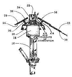
Figure 1 shows the main parts of the patio umbrella in a preferred
embodiment. In that embodiment, the umbrella is approximately eight feet in
diameter and approximately nine feet high. The umbrella includes a base 12. In
the
CA 02338583 2001-O1-25
WO 00/08965 PCT/US99/18046
7
preferred embodiment, plumbing for natural gas is brought into the base from
beneath the floor. In another embodiment, the base contains a tank of fuel,
such as
butane or propane, which permits the entire unit to be portable. The base 12
supports a table top 14, used for dining. A hollow steel column 16 extends
vertically out of the base, through the table top, and upward to support a
combustion chamber 18. The hollow column 16 encloses a fuel line through which
the fuel is brought to the combustion chamber.
The umbrella is shown in its open configuration in Figure 1, and Figure 5
shows it in the closed configuration. The canopy of the umbrella includes an
upper
centrally located canopy 20 and a lower canopy 22 that surrounds the upper
canopy 20. The lower edge of the upper canopy slightly overlaps the upper edge
of the lower canopy to facilitate runoffof moisture, but a vent opening is
maintained
between the upper canopy and the lower canopy to relieve air pressure
differences
which winds may cause.
Figure 2 is a top view of the umbrella of Figure 1 and shows the directions
in which the views of Figures 3 and 4 are taken.
As seen in Fig. 3, the upper canopy 20 lies on top of and is supported by the
upper canopy support 24. As suggested by Fig. 2, the upper canopy support is a
sheet metal structure having a frusto-pyramidal shape and formed from six
identical
four-sided sections that are joined along their lateral edges. The upper
canopy
support 24 is affixed to the reflector 28 by six insulative spacers, of which
the
spacer 26 is typical. Not only do the spacers 26 support the upper canopy
support 24, but in addition, they maintain a space 30 between the upper canopy
support 24 and the reflector 28, while at the same time defeating conduction
of heat
25 from the reflector 28 to the upper canopy support 24. The space between the
upper
edge of the upper canopy support and the reflector is important to permit the
upward discharge of air that has become heated and flows upwardly through the
space 30. This upward flow helps to prevent convective heating of the upper
canopy support 24, thereby helping to keep the upper canopy cool.
CA 02338583 2001-O1-25
WO 00/08965 PCT/US99/18046
8
The reflector 28 is a hollow sheet metal structure which surrounds the upper
portion ofthe combustion chamber 18, much like a lampshade surrounds an
electric
light bulb. The reflector 28 is connected the combustion chamber 18 by six
legs, of
which the leg 32 is typical. The legs 32 maintain a spacing between the
reflector 28
and the combustion chamber 18, and cooler air is drawn upward through that
space 36 helping to cool the reflector 28. Because the legs 32 are closer to
the
combustion chamber 18 and farther from the upper canopy, there was no
advantage
in making the legs of an insulative material.
Figure 3 is convenient to illustrate some of the techniques by which the
present inventors addressed the thermal problems that could result from
combining
a combustion heater with a cloth umbrella.
Conduction of heat is minimized by making the cross section of the legs 32
(perpendicular to the direction of heat flow) as small as possible consistent
with the
mechanical loads that the legs must support. Conduction between the reflector
28
and the upper canopy support 24 is minimized by the use of the insulative
spacers 26. In the preferred embodiment, the spacers 26 are composed of a
ceramic
material, and they include blind threaded holes at either end to avoid any
metallic
conduction path between the reflector 28 and the upper canopy support 24. In
these
ways the conduction of heat between the combustion chamber 18 and the upper
canopy support 24 is minimized by the present invention.
Radiative transfer is minimized by placing the upper canopy support 24 in
the shadow of the reflector 28. The reflector 28 disposes of a significant
part of the
radiation from the combustion chamber 18 by reflecting the radiation downward
toward the space surrounding the table top 14, where the radiation imparts a
comfortable warmth to persons sitting there. The under side of the upper
canopy
support 24 also reflects radiant heat, thereby further helping to keep the
upper
canopy cool.
A third way in which inventors addressed the thermal problems was by an
ingenious use of convection. The hot products of combustion are discharged
from
CA 02338583 2001-O1-25
WO 00/08965 PCT/US99/18046
9
the side of the combustion chamber 18, and they rise through the chimney
portion 34 of the reflector 28. In doing so, they create an updraft in the
space 36
between the combustion chamber 18 and the reflector 28. Were it not for this
space 36, the air would be trapped between the combustion chamber and the
reflector 28 and this air would become heated to a very high temperature,
thereby
causing the reflector to become much hotter than it does in the present
design.
Similarly, by not connecting the upper canopy support to the chimney portion
34 of
the reflector, the present inventors made it possible for hot air to be
discharged
upwardly along the chimney portion 34, as indicated by the arrows in Figure 3.
As
10 the hot air is discharged upwardly, it is replaced by cooler upwardly-
flowing air.
Again, this helps to keep the upper canopy support 24 at an acceptable
temperature.
Although protection of the upper canopy was more critical, because of its
closeness to the combustion chamber and its position above the combustion
chamber, protection of the lower canopy was also necessary. Unlike the upper
canopy which is supported on the upper canopy support 24, the lower canopy
simply spans the space between the ribs of the umbrella. The lower canopy must
remain pliable so that the umbrella can be closed. Even though the lower
canopy
is farther from the combustion chamber than the upper canopy is, the present
inventors found that the upper portion of the lower canopy required protection
from
heat damage. As best seen in Figure 4, they accomplished this by lining the
upper
portion of the lower canopy, on the side facing the combustion chamber, with a
layer 38 of aluminized reflective fire-resistant fabric. This fabric, which
has a silvery
metallic appearance was originally developed for use in the space program. It
combines high reflectivity (on the order of 90 per cent) with pliability and
durability.
The inventors found that the reflection caused by the lining 38 was sufficient
to
prevent overheating of the lower canopy. Radiative transfer of heat to the
lower
canopy is the only significant mode of heat transfer; the distances and
disposition of
the structure are such that convective and conductive modes are not
significant. In
CA 02338583 2001-O1-25
WO 00/08965 PCT1US99/18046
addition to protecting the lower canopy from overheating, the reflective
lining 38
also reflects radiant heat downward onto the table top and diners.
The lining 38 also serves to protect the lower canopy 22 in the event the
umbrella is closed while the combustion chamber 18 is hot; for example, if the
5 umbrella is closed immediately after the burner has been extinguished,
before the
combustion chamber has had time to cool.
As seen in Figure 2, Figure 4 is a cross sectional view taken in the plane of
one of the ribs 40 of the umbrella. While Figure 3 was useful in discussing
the
thermal aspects of the invention, Figure 4 is more useful in illustrating how
the
10 present inventors solved the mechanical problems inherent in integrating a
combustive heater with an umbrella.
The presence of the combustion chamber 18 and its associated reflector 28
presented the critical problems of where to attach the upper ends of the ribs;
and,
how to permit the umbrella to be closed without the ribs interfering with the
reflector 28.
The present inventors solved this problem by affixing six brackets, of which
the bracket 42 is typical, to the reflector 28. The brackets are riveted to
the
reflector and extend outwardly and downwardly parallel to the ridge lines of
the
canopy. The upper end of the rib 40 is attached to the lower end of the
bracket 42
by the pin 44, which permits the rib 40 to pivot up and down as the umbrella
is
opened and closed. The pin 44 is located further from the center of the
umbrella
than the reflector 28, and therefore the reflector does not interfere
mechanically with
the rib. The rib 40 is supported in the open position by the arm 46, which is
pivotally attached to the rib 40 by the pin 48. The lower end of the arm 46 is
pivotally attached to a sleeve 50 that slides up and down on the column 16.
The use
of a sliding sleeve and a support arm pivotally connected to the rib are
recognized
as old. The innovation of the present inventors was in attaching the top end
of the
rib to a stationary bracket affixed to the reflector 28 and in extending the
pivot
point 44 for the rib outward beyond the reflector. In this way, the reflector
does not
CA 02338583 2001-O1-25
WO 00/08965 PCT/US99/18046
11
interfere with the ribs, even when the umbrella is in its closed
configuration, as
shown in Figure 5.
This technique of mounting the ribs produced another advantage. Even
when the umbrella is in the folded configuration of Figure 5, the canopy does
not
extend downwardly far enough to intrude into the space between the persons
seated
around the table top 14, and thus does not block their view or interfere with
the
serving of food. In the preferred embodiment, when the umbrella is in the
closed
configuration, the lower edge of the canopy remains about two feet above the
table
top 14.
It is evident from Figure 4, that much of the weight of the canopy and ribs
is diverted through the arm 46 to the sleeve 50. Accordingly, the legs 32 are
not
required to support the entire weight of the canopy and ribs. This is what
permits
the legs to have a relatively small cross sectional area. Also, because of the
symmetry of the umbrella, static lateral loads on the legs 32 are relatively
small.
Also visible in Figure 5 is the actuator arm 52 of a microswitch. The
actuator arm extends through the wail of the hollow column i 6 and is actuated
by
the sleeve 50 as the sleeve passes over it. The microswitch, located within
the
hollow column 16, is turned on by upward passage of the sleeve 50 over the
actuator 52 and the microswitch is turned offby downward passage of the sleeve
50
over the actuator 52. The microswitch is connected to the fuel valve in such a
way
that closing of the umbrella extinguishes the combustion, which remains
disabled
until the microswitch is again actuated by upward passage of the sleeve 50 as
the
umbrella is again opened.
The controls of the heater have been simplified. In addition to the aforesaid
safety feature, the only other control is a knob 54 that is connected to a
timer.
Combustion is possible only when the timer is counting down. Thus, when the
diners are first seated, the waiter can initiate combustion by turning the
knob 54.
No further attention is required, because when the timer has run out, the
combustion
CA 02338583 2001-O1-25
WO 00/08965 PCT/US99/18046
12
ceases. This energy-saving feature has proven to be highly convenient; it is
not
necessary to remember to turn the heater off.
In practice, the measures taken by the inventors to solve the thermal and
mechanical problems inherent in integrating the combustion heater with the
cloth
umbrella have proven to be quite successful. The hottest reachable portion of
the
arm 46 is warm to the touch, but definitely not hot enough to cause a burn
when
touched.
Thus, there has been described the successful integration of a fuel-burning
radiant heater into a patio umbrella having a cloth canopy. This increases the
time
during which patio dining may be enjoyed, because the heaters can be used when
the
weather is cool, and the umbrellas can be used for protection against the sun.
The
combination is superior to having separate umbrellas and heaters, because in
the
latter case the heaters take up valuable floor space and impede the flow of
foot
traffic.
Industrial Applicability
The umbrella of the present invention has successfully solved the mechanical
problems, the thermal problems, and the air flow problems that arise from
attempting to integrate a fuel-burning radiant heater into a large flammable
cloth
5 patio umbrella. Some of the techniques used to solve these problems may also
find
use in the design of industrial heaters and related apparatus.