Note : Les descriptions sont présentées dans la langue officielle dans laquelle elles ont été soumises.
CA 02338814 2001-02-27
-1-
Title: P-TRAP FOR PLUMBING DRAINAGE SYSTEMS
FIELD OF THE INVENTION
This application relates to the plumbing field and more
particularly relates to the drainage side of plumbing systems. Most
particularly, this application relates to P-traps of the type that are used on
drains for sinks, tubs and the like.
BACKGROUND OF THE INVENTION
The plumbing and construction industries have for a long time
understood the necessity of employing a trap, to act as a vapour barrier,
between an open drain hole in a sink, for example, and a conduit to a sewer
system or septic holding tank. Such traps are configured to retain (trap) an
amount of water in a U-shaped bend which is sufficient to form the vapour
barrier against noxious sewer gases entering into living space through an
otherwise open drain. Such gasses are unhealthy and can cause sickness.
A conventional P-trap is formed from generally tubular drain
fittings, which may be fabricated from either metal or plastic. A conventional
trap is typically formed with the U bend to which is attached, for example, a
90 degree elbow at the outlet leg of the U. This elbow defines a generally
horizontal outletwhich can then be connected to appropriate drainage tubing
which is in turn connected to a sewer or septic system for the disposal of
liquid wastes. For P-traps made from plastic fittings the iniet leg of the U
is
typically solvent welded or frictionally coupled to a drain pipe which may for
example extend down from a sink or bathtub drain. Typically between the
90 degree elbow and the U is a joint which may be either a solvent joint, or
may be a detachable joint held together by a threaded connector. An
example of prior art systems with threaded joints are found in US Patents
4,352,368 and 3,719,209. The other outlet end of the elbow is also typically
solvent welded to the outflow drainage conduit.
CA 02338814 2001-02-27
-2-
Ideally such a P-trap is installed as follows. First the drain pipe
from the sink and the drain conduit connecting the sink to the septic or sewer
system are roughed in to an approximate location. The ends of these pipes
will be generally in the same area, but not attached. Then the P-trap is
installed between the free ends of the two pipes. The P-trap, comprising the
elbow and the u shaped tube tightly threaded together, is first solvent
welded at one end and then solvent welded at the other end. Then the
threaded joint can be undone or relaxed if needed for further manipulation
of the pipes.
However, what more typically happens is that the installer
positions the P-trap in place between the free ends, and then trims the ends
of the pipes to an appropriate length to accept the P-trap there-between.
The location of the trap is often very awkward; the pipes may be crammed
together under a sink in a vanity cabinet for example. So, typically, the
installer will undo the threaded connection, and then solvent cement or glue
or solvent weld, individually, the separated elbow and the u-shaped tube to
respective free ends of the pipes. Then, the installer uses the threaded
connector to draw the two components into a sealing relationship. While
easy, this method is problematic. It is very difficult to ensure the two
fittings
are both attached perfectly in the same plane. Further because they are
separated at the time they are attached, it is difficult to ensure that the
ends
are sufficiently close to permit the connector to easily couple the two ends
together.
As a result it can be difficult to make a leakproof joint at the
connection between the U-bend and the 90 degree elbow, because to do so
requires precise positioning of the two solvent welded fittings relative to
one
another at a time when they are separated. According to preferred
procedures, the threaded connection should be made tight between the
elbow and the U-shaped bend before welding the components in place.
However, where the elbow and U-shaped pipe are disconnected and each
independently solvent welded onto their respective drain pipe connections
misalignment usually occurs. The threaded coupler can compensate slightly
CA 02338814 2001-02-27
-3-
for misalignment because of the compression provided by the threaded
coupler onto a seal and the slight resiliency of a plastic pipe system. To
rely
on the inherent resiliency of the pipe system however essentially introduces
a strain into the system. A P-trap joint which is under pressure may not seal
properly or worse, it may seem sealed but over time due to the strain
introduced by misalignment may fail at a later date. Alternatively, if the
misalignment is large, the pressure generated by the threaded coupler as
the components are clamped together can be enough to cause a cracking
or opening of other drain pipe connections in the piping system.
Various types of couplings and connectors exist in the art,
including the following:
United States Patent 5,865,378 to Hollinshead et al;
United States Patent 5,449,206 to Lockwood;
United States Patent 3,891,246 to Hopper;
United States Patent 3,243,209 to Chertok;
United States Patent 3,034,809 to Greenberg;
United States Patent 2,388,633 to Woody;
United States Patent 1,829,101 to McGeorge;
United States Patent 1,695,263 to Jacques;
United States Patent 1,564,175 to Hoehn;
United States Patent 1,475,090 to Taylor;
United States Patent 1,187,642 to Milz;
United States Patent 885,256 to Jones; and
United States Patent 441,691 to McClellan.
What is required, therefore, is a P-trap assembly which
couples or connects to form a good liquid tight seal even when the
components are slightly out of alignment without creating unacceptable
stresses in either the P-trap assembly or any other part of the plumbing
system.
CA 02338814 2001-02-27
-4-
SUMMARY OF THE INVENTION
The present invention provides a coupler which is easy to
install and forms a secure joint. The coupler includes a connector with a
seal which can be used to connect together the 90 degree elbow and the U-
shaped fitting. First and second connector portions of the device are
configured so that they may be securable across a range of angles. This
provides a leakproof joint which can accommodate small variances in
alignment such as typically occur in the field. Therefore, according to the
present invention there is provided a
device for plumbing drainage systems said device comprising:
a firsttubing element having an attachment bell at one end and
a first coupler portion at the other end;
a second tubing element having an attachment bell at one end
and a second coupler portion at the other end, wherein said first and second
coupler portions are sized and shaped to be coupled together; and at least
one of said first or second tubing element is a generally u-shaped section
sized and shaped to trap water therein; and
a connector to releasably couple said first and second coupler
portions together, said connector including a sealing gasket, said sealing
gasket, first coupling portion and second coupling portion being sized and
shaped to permit said first and second coupler portions to be coupled
together over a range of angles to form a leak resistant joint.
According to a further aspect there is provided a device for
plumbing drainage systems, said device comprising:
a first tubing element having an attachment bell at one end and
a first coupler portion at the other end;
a second tubing element having an attachment bell at one end
and a second coupler portion at the other end, at least one of said first and
second tubing elements being generally U-shaped and sized and shaped to
trap water therein;
CA 02338814 2008-07-22
-5-
wherein said first and second coupler portions are sized and
shaped to permit said first and second coupler portions to be snapped
together over a range of angles to form a leak resistant joint.
BRIEF DESCRIPTION OF THE DRAWINGS
Reference will now be made to preferred embodiments of the
invention by way of example only with reference to the following figures:
Figure 1 is a cross-section of U of a device for plumbing
drainage systems according to the present invention comprised of an elbow
and a U-shaped bend;
Figure 2 is a view from above of one of the components from
Figure 1;
Figure 3 is an enlarged view of a portion of Figure 1 showing
details of the connection between the two fittings;
Figure 4 is a side sectional view of a further embodiment of the
present invention; and
Figure 5 is a side view of a further embodiment of the present
invention.
DETAILED DESCRIPTION OF THE PREFERRED EMBODIMENTS
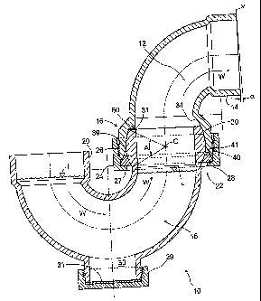
A device for plumbing and drainage systems according to the
present is indicated generally as 10 in Figure 1. The device includes a first
tubing element 12 having an attachment bell 14 and a first coupler portion
16 at the other end. The tubing element 12 is in the form of a 90 degree
elbow. Also shown is a second tubing element 18 having an attachment bell
20 at one end and a second coupler portion 22 at the other end. The
second tubing element 18 is in the form of a U-shaped tube. The u-shape
is sufficient in size and shape to retain water therein to form a vapour
barrier
when the device 10 is installed in a drainage system. A connector 24 is
shown having threads 26 to allow the connector to be releasably secured to
the device 10 as described below and also has an inwardly exteriding rim
27. Also shown is a seal 28 which is described in more detail below.
CA 02338814 2001-02-27
-6-
Also shown in Figure 1 is a threaded clean out cap 29, a clean
out gasket 31 on a clean out port 33. Waste flow is indicated by the arrows
W and the liquid trap level is shown by lines L.
Referring to the first coupler portion 16 in more detail, it can be
seen that in cross-section it is formed with a generally rounded outer surface
30. Most preferably the generally rounded outer surface 30 is part spherical
with a center (C) located on the axial centerline of the tubing element and
about midway down the connector portion 22 as shown. This forms the male
portion of the connection. It will be appreciated by those skilled in the art
that other centre points can be used and even that the surface need not be
a perfect part spherical section, but good results have been achieve with a
part spherical section as shown. As will also be appreciated the part
spherical section extends fully around the tubing element similar to a
conventional flange as shown in Figure 2. This part spherical section is
described below as a bulb or ball. Most preferably this surface will be
sufficiently smooth to permit a seal to be formed there-against. Good results
have been obtained by providing a surface smoothness SPE #2 finish.
Referring now to the second coupler portion 22, it can be seen
as having part spherical inside surface 34 or socket or female part to closely
receive the outside ball shaped surface 30 described above. Again most
preferably the inside surface 34 is part spherical so that it matches the bulb
portion when the bulb is inserted in the socket. Again the inside surface is
also preferable of a smoothness to permit a good liquid tight seal to be
formed there-against.
As can be seen, the inside surface is curved or dished to an
inflection point 39 after which the surface extends away from a centerline to
form an angled lower lip 40. The angled lip 40 defines a wedge shaped gap
41 in cross section, between the lip 40 and the outer rounded surface 30 of
the male part when the male and female parts are assembled together. This
wedge shaped gap 41 is important in forming a liquid tight seal as explained
in more detail below.
CA 02338814 2001-02-27
-7-
Figure 3 shows an enlarged view of the coupler portions 16
and 22 of Figure 1. Referring now to the seal 28, most preferably the seal
28 is in the form of a generally wedge-shaped gasket in cross-section
having an internal sealing face 44, an external sealing face 46 and a bottom
face 47. Most preferably the gasket is in the form of a continuous ring when
viewed from above. The internal sealing face 44 must closely match the part
spherical surface 30 of the bulb or male part to form a good seal. Matching
of the surfaces can be accomplished by making the seal 28 from a partially
compressible material which will conform to the outer surface shape 30 or
by making the sealing gasket 28 from a less compressible material which is
shaped to have a matching curvature to that of the outer surface 30. As will
be appreciated by those skilled in the art the sealing could also be effected
by using a combination of compression and shaping of the seal 28. Good
results have been achieved to date with the former approach through the
use of a molded linear low density polyethylene seal 28 which is shaped with
a surface which matches the outer surface 30 closely enough to be easily
sealable there-against under a moderate compressive force. This is shown
at 45 in Figure 3.
Turning now to the outer face 46 of the seal 28, this is most
preferably conical with the face 46 having a pitch to match the angled portion
of the lip 40. The purpose of the face 46 is to translate axial forces (those
parallel to the central axis of the pipe) exerted on the seal as the threaded
connector is drawn into compressive engagement, into radially compressive
forces to cause a good seal between the surface 30 and the sealing face 44.
Again most preferably the lip 40 and the outer face 46 should be smooth
enough to allow a good seal and to also allow the seal 28 to slip past the lip
40 while device is being tightened together as explained in more detail
below.
The bottom face 47 is most preferably flat, and acts as a
driving or thrust surface for rim 27 of the threaded connector.
It can now be appreciated how the present invention operates.
To assemble the device, the seal 28 is inserted into the connector 24 which
CA 02338814 2008-07-22
-8-
in turn is positioned around the u-shaped tube just below the bulb. Then,
the elbow 12 is brought close enough to permit the threads of the connector
to engage the threads of the elbow. As the connector 24 is threaded on to
the second tubing element, it will draw the elbow 12 down onto the u-shaped
tube. This will have cause the outer surface 30 to move closer to the inner
surface 34. As well, the seal 28 will be compressed into an ever- smaller
wedge shaped gap 41 as the parts come together and as the rim 27 drives
the bottom edge 47 of the seal 28 higher than the gap 41. The seal will be
urged into the gap 41 by the rim 25 acting on the surface 47 of the seal 28
causing the seal 28 to compress against both the part spherical surface 30
and the angled surface 42. In this way the seal can be compressed to form
a leakproof joint between the two elements 12 and 18.
It can now be appreciated that the choice of linear lov/ density
polyethylene, which has a relatively low fictional coefficient is an
advantage,
since this will lower the resistance to turning the connector 24 on as the
seal
28 engages in the wedge shaped gap 41. The rim 27 slips past the thrust
face 47 of the seal 28 during final tightenening.
It can now be appreciated that by reason of the part spherical
surface 30 it is possible to form a liquid tight seal even though the
respective
elements 12 and 18 may be out of angular alignment. All that is required is
for the part spherical surface to extend over a sufficient vertical radial arc
to
permit the seal to be lower at one point and higher at another point while
still
forming a good seal fully around the circumference of the tubing elements.
Thus, because of the part spherical surface, the seal will be formed tight and
continuous even though variations in angle may be present between the two
components. Further, the seal so formed will not impose any stresses onto
the plumbing connections by reason of any forced alignment as occurs with
the prior art devices. Thus, once the seal of the present invention is formed,
it will tend to keep its integrity over time and there is also likely to be
less
collateral damage to other parts of the installed plumbing system.
It can now be appreciated that the range of angular variation
is defined by the extent of the part spherical surfaces 30 and 34. Although
CA 02338814 2008-07-22
-9-
more is preferred than less, to give a greater range of sealing angles,
adequate results have been achieved where the arc angle subtended
(shown as A) between the top and bottom of the part spherical si.arface is
between 200 and 90 , and most preferably between 30 and 50 . As shown,
the subtended arc angle is about 450
.
Returning now to the shape of the internal surface 44 of the
seal 28 it will be noted that the seal will be driven by the rim 27 into
engagement with the part spherical surface. One preferred shape for the
seal surface is therefore also a part spherical surface which has the same
radius of curvature as the male part. Other shapes can be used, provided
that the material chosen for the seal is compressible enough to seal against
the rounded surface. As will be appreciated, most compressible rnaterials
tend to have higher coefficients of friction which is why the more closely
shaped, less compressible, low friction properties of low density plastic such
as polyethylene is believed the most preferred.
In a further embodiment shown in Figure 4, a bevel surface
100 is provided on the threaded connector 24. Thus, as the conriector 24
is tightened, the bevel causes a side thrust forcing the seal 28 to engage
even more tightly. Further, rather than being a separate component, the
seal 28 could be made integral with either the connector on the female
portion of the joint.
While reference has been made to a particular form of sealing
element, it will be understood that the present invention comprehends other
forms of sealing element. For example in Figure 5, an 0-ring 110 type of
sealing element is shown. In this embodiment a groove 112 is formed into
the female portion. That the 0-ring could be equally mounted into the part
spherical surface is also comprehended by the present invention. As will be
understood, the shape of the seal and the type of seal are less important
than the location of the seal. The angular possibilities of connection of the
present invention are achieved by sealing against a rounded or part
spherical surface. Angular variations in the connection between the
CA 02338814 2001-02-27
-10-
elements therefore do not affect the ability to form a seal, unlike in the
prior
art.
A further aspect of the present invention can now be
understood. According to most building codes, all drainage plumbing must
be sloped or inclined so that the drainage pipes drain towards the sewer to
transport waste out of the building or dwelling. This ensures that the waste
does not sit in the pipes and thus reaches and can be treated in an
appropriate sewage or wastewater treatment facility. Thus, there is a need
to establish, in domestic or other building plumbing a desired fall of the
drainage pipe when it is first positioned in the building.
The present invention provides for an automatic provision of
a desired amount of minimum fall through the fitting. This is accomplished
by means of a stop 60 in the socket or female connector portion. The stop
60 is sized and shaped so that it engages an upper edge or lip 63 of the u-
shaped tube 18. Further the stop is sized and shaped to provide that when
the stop 60 is in contact with the lip 63 of the u-shaped portion the fitting
element 18 is angled slightly down to a predetermined angle or fall. This is
depicted by the angle alpha which is formed between vertical (shown as V)
and a line connecting the end of the attachment bell 14. Good results have
been achieved when the angle so formed is at least one to three degrees
and most preferably is about 1 degree. This angle will cause the part 18 to
be angled downwardly thus permitting the device to be installed in a position
which promotes the flow or drainage of waste from the fitting and from any
piping axially connected to the fitting. It is preferred to position the stop
on
the opposite side of the fitting 12 from the outflow. In this manner the stop
permits the fitting to be installed with an angle greater than 1 but prevents
the fitting from being installed at an angle of less than 1 . In this way, the
stop prevents the fitting 12 from being installed horizontal, or with an
uphill
rise on the outflow end. Thus, because the fitting is so angled, any pipe
plumbed into the fitting will also have the desired fall already established.
In this way use of the present invention promotes proper sloping of the
drainage plumbing.
CA 02338814 2001-02-27
-11-
Figure 5 teaches a further embodiment of the present
invention. In this embodiment there is no connector per se, rather, the
female portion 16 is sized and shaped to be resiliently snapped over the
male portion. A sealing ring 110, such as an 0-ring in a groove 112, is
pressed into engagement between the two parts to form a seal. This
embodiment is somewhat simpler, but does not include a positive lock
between the two parts which may not be preferred in some cases.
While reference has been made to preferred embodiments of
the present invention, various modifications and alterations are
contemplated and comprehended by the scope of the appended claims.
Some of the modifications have been discussed above and other will be
apparent to those skilled in the art. For example, while the preferred seal
material is low density polyethylene, other seal materials could be
substituted therefor without much difficulty. Further, while the preferred
size
and position of the stop results in a 10 slope, more could be provided if
desired.