Note : Les descriptions sont présentées dans la langue officielle dans laquelle elles ont été soumises.
CA 02339706 2001-03-02
HEAT SHIELDING APPARATUS FOR
VERTICAL CONTINUOUS A~I~NEAL1NG FURNACE
1. Field of Inve~gtion
S This invention relates to a heat shielding apparatus for a vertical
continuous
annealing furnace in which heat treatment is performed on a metal strip white
the strip
is continuously transported.
2. pe~~ritst~n~ ef Rel tCd rt
Recently, an annealing pmcess for reerystallizixig steel strip ai~er being
subjected to cold rolling and for imparting good workability to the steel
strip has been
primarily carried out by continuous annealing instead of batch annealing. As a
continuous annealing furnace fox carrying out the continuous annealing, there
are
known horizontal continuous annealing furnaces, in which annealing is
performed on
a strip traveling along a horizontal pass, and vertical continuous annealing
furnaces, in
which a plurality of rolls are arranged in upper and lower portions of the
flunace and
annealing is performed on a strip traveling along a vertical pass. Of these
continuous
annealing furnaces, the vertical furnace is more advantageous for a mass-
production
process that is realized by increasing the passing (threading) speed of the
strip.
Also, at present, indirect heating using a radiant tube is prevalent as a
heating
24 source for the vertical continuous annealing furnace, and steel strip is
mainly heated
with radiant heat from the heating source.
In s vertical continuous annealing furnace wherein a plurality of rolls are
arranged in upper and lower portions of the furnace and annealing is performed
on a
steel strip being transported in the verkical direction by the rolls, while
changing a
travel direction from upward to downward or vice versa as the strip turns
around each
roll, it is important to prevent the steel strip from snals~g or mistracking
and to ensure
stable passage of the strip, Generally, as shown in Fig. 11, each roll 12
arranged in
the ~urnsce is designed to have a convex roll crown with both shoulders
tapered
toward the ends. This design is intended to make the steel strip pass the
furnace so
that the strip always travels nn match with the roll center, by utilizing a
centering force
(arrow F) acting on the strip, which has ridden over a tapered portion, in a
direction
CA 02339706 2001-03-02
from the roll edge toward the roll center based on a self centering motion of
the strip
wound on the tapered portion of the roll with angle.
As shown in Fig. 12, however, radiant heat from a heating source (e.g., a
radiant tube) 14 provided in the furnace heats not only a steel strip 10, but
also the roll
12 arranged in the furnace. Therefore, an actual crown of the roll arranged in
the
Furnace is given by the stun of a crown initially imparted to the roll (called
as initial
crown) and a crown imparted by the radiant heat from the heating source
(called a
thermal crown). As a result, when the ter»petature of the steel strip is lower
than the
roll temperature and when the thermal crown is larger thane the initial crown,
the
temperature of a roll central portion is relatively reduced and the roll crown
is
rendered concave as indicated by solid lines in Fig. 12. rf the steel strip 10
travels
over the roll 12 having such a concave crown, a force produced in the width
direction
of the steel strip acts from the roll center toward the roll edge.
Accordingly, once the
steel strip undergoes snaking or misbracking, the strip is foxced to ride over
the roll
edge beyond it at a stroke, which causes the problem during the strip passage
that the
strip comes into contact with the fiunace wall.
To cope with this problem, some devices are proposed to prevent the roll
temperature from being higher than the strip temperature , so, a shield plate
has
previously been pxovided to intercept the heat radiated from the heating
source 14
toward the roll 12, as disclosed in Japanese Unexamined Utility Model
Application
Publication No. 63-119661. Also, Japanese Unexamined Patent Application
Publication No. 57-79123 discloses a shielding apparatus employing a heat-
resistant
tube through which sir, nitrogen gas or the like, flows for cooling.
Further, in view of the finding that a shield plate alone is not su~cient to
suppress the thermal crown, Japanese Unexamined Patent Application Publication
No, 52-71318 discloses a technique for spraying cooling gas to the roll to
control the
thermal crown in a positive way. Moreover, for the same purpose, Japanese
Unexamined Patent Application Publication No. 53-119208 discloses a technique
for
water-cooling a roll edge portion, or changing a thermal conductivity between
the roll .
central portion and the roll edge poxtion. In addition, Japanese Unexamined
Patent
Application Publication No. 53-130210 and Japanese Examined Patent Publication
2
CA 02339706 2001-03-02
No. 57-23733 disclose techniques for arranging, separately from the rolls, a
cooling
apparatus that forms a cooling flow path.
Among the above-mentioned examples of the related art, techniques fox
suppressing the thermal cmwn imparted to the roll in a positive way are
effective in
preventing snaking of the strip, but have the problem of requiring a very
large amount
of equipment investment. Another problem is that, because of an increase in
size of
the apparatus itself, heat capacity of the apparatus is necessarily increased,
which
deteriorates the fuel unit consumption in the heating zone,
This invention has been made with the view of overcoming the above-
described problems of the related art. An object of this invention is to
provide an
inexpensive and more efficient apparatus on the basis of the radiant heat
shielding
apparatus employing a cooling tube, which is disclosed in the above-cited
Japanese
Unexamined Patent Application Publication No. 57-79123, for example.
To achieve the above object, this invention provides a xadiant heat shielding
apparatus for a vertical continuous annealing furnace, in which a plurality of
rolls are
arranged in upper and lower portions of the ~Rimace sad heat treatment is
performed
on metal strip continuously transported by the rolls. The strip is transported
in the
vertical direction by the rolls while changing the travel direction from
upward to
downward, ox from downward to upward, as the metal strip turns around each of
the
rolls. The radiant heat shielding apparatus is disposed below the roll
positioned in the
upper portion of the furnace, and/or above the roll positioned in the lower
portion of
the furnace, for intercepting heat radiated from a heating source provided
within the
fiuz~.ace. Preferably, the radiant heat shielding apparatus is positioned just
below the
roll in the upper portion of the furnace, and/or just above the roll in the
lower portion
of the furnace. The radiant heat shielding apparatus comprises a double-walled
tube
including an inner tube having an outside atmosphere suction port projected
horizontally or downward to be exposed to an outside atmosphere, and an outer
tube
having an exhaust port projected upward to be exposed to the outside
atmosphere.
In the radiant heat shielding apparatus, preferably, the outer diameter D of
the
outer tube of the double-walled tube is not less than about 60 mm, the level
difference
H between the outside atmosphere suction port and the exhaust port of the
double-
3
CA 02339706 2001-03-02
walled tube is not less than about 150 mm, and the outer diameter D (unit: m)
of the
outer tube of the double-walled tube and the level difference H (unit: m)
satisfy the
following relationship:
DZx~22.2x10⁻³ ...(1)
Further, according to this inve~ion, some embodiments of the radiant heat
shielding apparatus comprise a plurality of double-walled tubes as described
above.
The double-walled tubes are horizontally arranged just below the roll
positioned in the
upper portion of the furnace and/or just above the roll positioned in the
lower portion
ofthe fiunace.
I O Alternatively, in some embodiments, the radiant heat shielding apparatus
comprises one or more double-walled tubes as described above, and the double-
walled
tubes are used as support tubes and a shield plate is attached to the support
tubes.
BRIEF DE C13IPTION OF THF p~~,AWINCS
Fig. 1 is a vertical sectional view showing the construction of a double-
walled
15 tube for use in a first embodiment of a radiant heat shielding apparatus
according to
this invention;
Fig. 2 includes side views and front views showing, for comparison,
arrangements of a conventional example using a flat plate, a comparative
example
using a simple cooling tube, and the first embodiment using a cooling tube in
the form
20 of the double-walled tube according to this invention;
Fig. 3 is a graph showing, for comparison, the relationships between the flow
rate of cooling gas (Q) and the surface temperature of an outer tube of each
double-
walled tube and a flax plate for explaining the principles of this invention;
Fig. 4 is a graph showing the relationship among the flow rate of cooling gas,
25 the temperature difference (DT) on a roll in the width direction of a
strip, and the
occurrence of snalang of the strip;
Fig. 5 is a graph showing the relationship between the flow rate of cooling
gas
and the product of the square of an outer diameter (D) of the outer tube and
the square
root of level difference (I-~;
30 Fig. 6 is a graph showing the telarionship between the flow rate of cooling
gas
(Q) and the level difference (I~;
4
CA 02339706 2001-03-02
Fig. 7 is a side view showing the construction of a second embodiment of the
radiant heat shielding apparatus according to this invention;
Fig. 8 is a side view showing the construction of a third embodiment of the
radiant heat shielding apparatus according to this invention;
Fig. 9 is a graph showing, fox comparison, the incidence of snaking in the
conventional example using a flat plate, the comparative example using a
simple
cooling tube, and this invention;
Fig. 10 is a graph showing, for comparison, the replacement frequency of the
radiant heat shielding apparatus in the conventional example, the comparative
example, and this invention;
Fig. 11 is a front view showing a roll that is arranged in a ~ and has a
convex roll crown;
Fig. 12 is a front view showing a state where a strip is transported by a roll
that
is arranged in a furnace and has a concave crown due to a thermal crown
imparted to
the roll; and
Fig. 13 is a schematic view of an annealing furnace including an embodiment
of the radiant heat shielding apparatus of this invention.
Embodiments of this invention will be described below in detail with reference
to the drawings.
A radiant heat shielding apparatus of this invention is disposed below
(preferably just below) a roll positioned in an upper portion of a vertical
continuous
annealing furnace, and/or positioned above (preferably just above) a roll
positioned in
a lower portion of the furnace, for intercepting heat radiated from a heating
source that
is provided within the furnace, and the heat shielding apparatus is almost
parallel to
the roll.
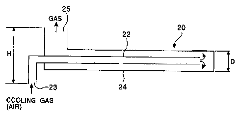
In a first ernbadiment of this invention, as shown in Fig. 1, the radiant heat
shielding apparatus has a structure of a double-walled tube 20 comprising an
inner
tube 2Z having an, outside atmosphere suction port 23 projected downward to be
exposed to an outside atmosphere, and an outer tube 24 having an exhaust poet
25
projected upward to be exposed to the outside atmosphere, With such a
structure, an
5
CA 02339706 2001-03-02
inexpensive and more efficient radiant heat shielding apparatus can be
realized by
effectively utilizing natural convection of the outside atmosphere (e.g.,
air).
Further, as a result of repeated experiments on the xelationship among the
flow
rate of cooling gas (air) flowing through the double-walled tube 20, a radiant
heat
shielding effect, and high-temperature creep resistance of the double-walled
tube, the
inventors discovered a condition range suitable for intercepting the radiant
heat in
which an outer diameter D of the outer tube 24 of the double-walled tube 20 is
not
less than about 60 mrn, a level difference (distance) H between the outside
atmosphere
suction port 23 and the exhaust port 25 is not less than about 150 mm, and the
outer
diameter D (unit: m) of the outer tube 24 of the double-walled tube and the
level
difference H (unit: m) satisfy the following formula (1):
Dz x ~~ 2.2 X 10'~ ...(1)
Heat-resistant alloy steel is an exemplary suitable material for forming the
double-walled tube 20. For example, staixaless steel having a Cr content of
not less
than about 18 wt% and a Ni content of not less than about $ wt%, or special
steel
having high heat resistance, are preferred materials.
The inventors discovered that the radiant heat shielding apparatus employing a
conventional cooling tube, disclosed in Japanese Unexamined Patent Application
Publication No. 57-79123, has a limitation in its cooling capability utilizing
natural
convection of an outside atmosphere (air). Japanese Unexamined Patent
Application
Publication No. S7-79123 discloses that air for cooling is forced to flow into
the
cooling tube by a suction blower, or by a pressure blower. However, when a
blower is
provided on the suction side, the blower sucks exhaust gas at high
temperatures, and
therefore the blower must itself be made heat-resistant, or else a device for
cooling
suction gas must be provided upstr~act~ of the blower. In any case, the
equipment cost
is necessarily increased. On the other hand, when a pressure blower is used to
force
the cooling air to flow into the cooling tube, there is risk that a metal (or
steel) strip is
oxidized due to leakage of the air from the cooling tube into the fiuxuace.
Based on the about findings, the inventors fabricated radiant heat shielding
apparatuses having three types of structures shown in Fig. 2, and conducted
tests on
those actual apparatuses.
b
CA 02339706 2001-03-02
'The left side of Fig. 2 represents a conventional example using a shield
plate
16 in the form of a simple flat plate. A strip 10 (typically, a steel strip);
a roll 12
arranged in a furnace; and a heating source 14 (typically, a radiant tube) are
shown.
The center of Fig. 2 represents a comparative example using a cooling tube 18
in the
form of a simple straight double-walled tube. The right side of Fig. 2
represents the
first embodiment of this invention including a cooling tube 20 in the form of
the
double-walled tube shown in Fig. 1,
Fig. 3 is a graph showing test results obtained by measuring a surface
temperature of an outer tube of each double-walled tube and a flat plate (on
the side
facing the roll 12 arranged in the furnace), which is represented by the
vertical axis,
relative to a flow rate of cooling gas (nix) measured at the exhaust port of
the outer
tube of each double-walled tube, which is represented by the horizontal axis,
Measurement conditions were set such that the f~urnaae temperature was
900°C, the
temperature of the outside atmosphere (cooling gas) was 300 ° C, the
outer tube
diameter of the double-walled tube was 100 mna, the inner tube diameter of the
double-walled tube was 40 mm, and the level difference F1 between the outside
atmosphere suction port 23 and the exhaust port 25 of the double-walled tube
was
200 mm.
In the comparative example using the cooling tube (simple straight double-
walled tube) is which no improvements were made on the outside atmosphere
suction
port and the exhaust port, as indicated by m~rJ~,s D in Fig. 3, the flow rate
of the
cooling gas due to natural convection was small and the outer tube surface
temperature of the double-walled tube reached 800 °C.
In the conventional example (using the flat plate), as indicated by marks D,
the
surface temperature of the flat plate reached 860°C.
By contrast, in the first embodiment of this invention in which the double-
walled tube was improved to have the outside atmosphere suction port and the
exhaust
port projected respectively downward and upward to be exposed to the outside
atmosphere, as indicated by marks o in Fig. 3, the flow rate of the cooling
gas reached
to 5,0 X 10'' (Nm'/s) and the surface temperature of the outer tube was
reduced down
to about 500 ° C.
7
CA 02339706 2001-03-02
Fig. 4 is a graph showing the relationship between the flow rate of cooling
gas
(air) measured at the exhaust port of the outer tube of the double-walled tube
according to this iuatvention and a temperature difference aT developed on a
temperature measuring roll is the width direction of a strip. The roll
temperature
measured had thermocouples embedded therein in the width direction of the roll
and
was positioned just above the radiant heat shielding apparatus which is almost
perelsll
to the roll. Measurement conditions were set such that the length of a roll
barrel was
2000 mm, the average width of steel slxips passed through the furnace was 1260
mrn,
aetd the average furnace temperature was 900 ° C. Hereixa, the
temperature difference
t1T was defined by OT ~ Te (roll surface temperature at a poi~at spaced 100 mm
from
the roll edge) - Tc (ml! surface temperature at the roll center). The graph of
Fig. 4
shows that the minimum temperature difference DT, at which the roll crown is
rendered concave and the steel strip undergoes snaking, is about 150 °
C, and that the
flow rate of the cooling gas required for preventing snaking of the steel
strip is not
less than 3.0 x 10'' (Nm'/s).
In the above-descn'bod first embodiment of this invention, the outside
atmosphere suction port is described as being projected downward. However, the
outside atmosphere suction port is not limited to such an arrangement. The
outside
atmosphere suction port may alternatively be projected at a different
orientation, e.g.,
horizontally.
Tn the radiant heat shielding apparatus according to this invention, which
comprises a double-walled tube haviut~g art outside atmosphere suction port
projected
horizontally or downward to be exposed to the outside atmosphere, and an
exhaust
port projected upward to be exposed to the outside atmosphere, the chimney
effect
developed on a flow in the double-walled tube from suction of the outside
atmosphere
to exhaust thereof is utilized to satisfy the above-xrtentioned required flow
rate of the
cooling gas.
From the law of conservation of mass for a fluid, the flow rate Q (m3/s) of
the
cooling gas is given by the following equation:
Q = Vg x ~ x (D/2)2 .
..(2)
where Vg is the flow speed (m/s) of the cooling gas at the exhaust port and D
is the
outer diameter (rn) of the outer tube.
8
CA 02339706 2001-03-02
Also, from the Iaw of conservation of energy for a fluid, the flow speed (m/s)
of the cooling gas at the exhaust port is given by the following equation:
vg - ~ (...(3)
where g is the acceleration of gravity (~ 9.8 ~oa/s2) and H is the level
difference (m)
between the outside atmosphere suction port and the exhaust port of the double-
walled tube,
Combining formulae (2) and (3) results in the formula:
Q = JX ~r x (D/2)Z , . . (4)
According to formula (4), the flow rate Q of the cooling gas is proportional
to
the outer diameter D of the outer tube and is also proportional to the square
mot of the
level difference H between the outside atmosphere suction port and the exhaust
port
of the double-walled tube.
Fig. 5 is a graph plotting actually measured data representing the
relationship
between the parameter D2 x ~ indicated by the horizontal axis, and the flow
rate Q
(Nm'%s) of the cooling gas, indicated by the vertical axis. The graph of Fig.
5 shows
that Dz x ~ z 2.2 X 10'' is needed to satisfy the required flow rate Q of the
cooling
gas that is not less than about 3.0 x 10'' (Nm'/s). Stated otherwise, it is
lmown that
the furnace temperature ranges from about 500°C to about 900°C
during actual
operation, and when the furnace is within this temperatwre range, the flow
rate of the
cooling gas not less than the above-mentioned value is sufficient to achieve
the
desired cooling. Thus, if Di x ,/ (I~ z 2.2 X 10⁻³ is satisfied, a sut~cient
cooling effect
can be provided during actual operation.
Fig. 6 is a graph showing the relationship between the flow rate Q (Nm3/s) of
the cooling gas and the level difference H (mm) between the outside atmosphere
suction port and the exhaust port of the double-walled tube. The graph of Fig.
6
shows that if the level difference is less than about 150 mtn, the cooling gas
becomes
difficult to flow because the Ievel difference H is substantially at the samte
level as that
corresponding to the diameter of the double-walled tube. Therefore, the level
digerence H between the outside atmosphere suction port sad the exhaust port
of the
double-walled tube is preferably set to be not less than about 150 mm..
Also, if the outer diameter of the outer tube of the double-walled tube is
small,
the outer tube is more easily susceptible to creep due to the radiant heat.
From the
9
CA 02339706 2001-03-02
actual operation of the invention experienced so far, it has been confirmed
that the
outer diameter of the outer tube is preferably not less them about 60 mm.
Further, the outer diameter ratio between the outer tube and the inner tube of
the double-walled tube is preferably in the range of from about 2.0 to about
4Ø
The outer tube is preferably made of stainless steel having a Cr content of
trot
less thaa about 18 wt% and a Ni content of not less than about 8 wt%, which is
represented by, for example, SUS304, SUS316 and SUS316L according to the JIS
(Japanese Industrial Standards).
When installing the double-walled tube, the outside atmosphere suction port of
the double-walled tube is preferably spaced about 100 xwm. or more from the
furnace
wall.
When the roll arranged in the furnace has a diameter several times as large as
that of the double-walled tube of the radiant heat shielding apparatus, it is
di~cult to
sufficiently intercept the heat radiated from the heating source toward the
roll surface
by usiung the radiant heat sbdelding apparatus that comprises one unit of
doublo-walled
tube. In such case, the radiant heat can be effectively intercepted by other
embodiments of this invention shown in Figs. 7 and 8. In the second embodiment
of
the invention shown in Fig. 7, a plurality of double-walled tubes 20 are
aaanged side-
by-side horizontally just below the roll positioned in the upper portion of
the furnace,
and/or positioned just above the roll positioned in the lower portion of the
fu:nacc.
In the third embodiment of the invention shown in Fig. S, one or more (two are
shown) double--walled tubes 20 are used as support tubes and a shield plate 30
is
attached to the support tubes as illustrated. Figs. '1 and 8 also show the
arrangement
of rolls 12, heating sources 14 and strips 10.
Based on the above-described results obtained from the tests performed on
actual apparatuses, the double-walled tube shown in Fig. 1 was fabricated
using
SUS316 stainless steel. The double-walled tube had an outer diameter D of the
outer
tube of 114.3 mm, an inner diameter of the outer tube of 97.1 mtn, an outer
diameter
of the inner tube of 48.0 mm, and an inner diameter of the inner tube of 41.2
mm,
The level difference H between the outside atmosphere suction port and the
exhaust
port of the double-walled tube was 200 mm, A plurality of radiant heat
shielding
CA 02339706 2001-03-02
apparatuses each comprising the double-walled tube thus fabricated were
installed in
upper and lower stages of a heating none of a vertical continuous annealing
furnace, as
shown in Fig. 13. The radiant heat shielding apparatus was installed in the
upper
stage of the heating zone at a level spaced 400 mm from each roll just below
it. Also,
the radiant heat shielding apparatus was installed in the lower stage of the
heating
zone at a level spaced 400 mm from each roll just above it. The shielding
effect of the
actually installed radiant heat shielding apparatus was measured by operating
the
furnace for about two years under ordinary conditions.
Results of the measurement are shown in Fig. 9 (incidence of snaking) and
Fig. 10 (replacement frequency of the radiant heat shielding apparatus). Xtt
this
invention, as shown in Fig. 9, the incidence of snaking is reduced down to
about 1/3
as compared with both the conventional and comparative radiant heat shielding
apparatuses using respectively a flat plate and a simple cooling tube. Also,
as shown
in Fig, 10, the useful life of the radiant heat shielding apparatus is greatly
prolonged in
1 S this invention as compared with both the conventional, and comparative
apparatuses,
because the cooling action is enhanced in this invention by effectively
utilizing the
chimney effect developed on a flow in the cooling tube from suction of the
outside
atmosphere to exhaust thereof,
Additionally, in the arrangement of Fig. 13, the radiant heat shielding
apparatus of this invention including double-walled tubes 20 is disposed in
the upper
stage at a position between adjacent passes, i.e., at a position not just
below each
roll 12, as well, The shielding effect can be increased by so arranging the
radiant heat
shielding apparatus.
As described above, this invention ca:n provide a radiant heat shielding
apparatus, which is inexpensive, effective in preventing snaking of a strip,
and has the
prolonged useful life, because of effective utilization of the chimney effect
that is
developed for flow in a double-walled cooling tube from suction of an outside
atmosphere to exhaust thereof.
11