Sélection de la langue

Search

Sommaire du brevet 2340273 

Énoncé de désistement de responsabilité concernant l'information provenant de tiers

Une partie des informations de ce site Web a été fournie par des sources externes. Le gouvernement du Canada n'assume aucune responsabilité concernant la précision, l'actualité ou la fiabilité des informations fournies par les sources externes. Les utilisateurs qui désirent employer cette information devraient consulter directement la source des informations. Le contenu fourni par les sources externes n'est pas assujetti aux exigences sur les langues officielles, la protection des renseignements personnels et l'accessibilité.

Disponibilité de l'Abrégé et des Revendications

L'apparition de différences dans le texte et l'image des Revendications et de l'Abrégé dépend du moment auquel le document est publié. Les textes des Revendications et de l'Abrégé sont affichés :

  • lorsque la demande peut être examinée par le public;
  • lorsque le brevet est émis (délivrance).
(12) Brevet: (11) CA 2340273
(54) Titre français: SYSTEME DE REVETEMENT ELECTROSTATIQUE ET COUPELLE A DEUX REBORDS POUR UN TEL SYSTEME
(54) Titre anglais: ELECTROSTATIC COATING SYSTEM AND DUAL LIP BELL CUP THEREFOR
Statut: Périmé et au-delà du délai pour l’annulation
Données bibliographiques
(51) Classification internationale des brevets (CIB):
  • B05B 5/04 (2006.01)
  • B05B 12/14 (2006.01)
(72) Inventeurs :
  • ALLEN, HAROLD T. (Etats-Unis d'Amérique)
(73) Titulaires :
  • FINISHING BRANDS HOLDINGS INC.
(71) Demandeurs :
  • FINISHING BRANDS HOLDINGS INC. (Etats-Unis d'Amérique)
(74) Agent: FINLAYSON & SINGLEHURST
(74) Co-agent:
(45) Délivré: 2006-10-24
(22) Date de dépôt: 2001-03-09
(41) Mise à la disponibilité du public: 2001-09-14
Requête d'examen: 2001-03-09
Licence disponible: S.O.
Cédé au domaine public: S.O.
(25) Langue des documents déposés: Anglais

Traité de coopération en matière de brevets (PCT): Non

(30) Données de priorité de la demande:
Numéro de la demande Pays / territoire Date
09/525,141 (Etats-Unis d'Amérique) 2000-03-14

Abrégés

Abrégé français

Système de revêtement électrostatique, muni d'un dispositif de pulvérisation rotatif, formé d'un élément de corps non conducteur ayant une ouverture dans une extrémité externe de celui-ci, un élément semi-conducteur étant disposé sur une partie latérale de l'élément de corps, un premier rebord dépourvu de l'élément semi-conducteur étant disposé autour de l'ouverture de l'élément de corps à proximité de l'extrémité externe de celui-ci, et un deuxième rebord étant disposé radialement vers l'extérieur du premier rebord, entre le premier rebord et l'extrémité interne de l'élément de corps.


Abrégé anglais

An electrostatic coating system having a rotary atomizing device formed of a non-conductive body member having an opening in an outer end thereof, a semiconductive member is disposed on a side portion of the body member, a first lip devoid of the semiconductive member is disposed about the opening of the body member proximate the outer end thereof, and a second lip is disposed radially outwardly of the first lip, between the first lip and the inner end of the body member.

Revendications

Note : Les revendications sont présentées dans la langue officielle dans laquelle elles ont été soumises.


The embodiments of the invention in which an exclusive property or privilege
is claimed-
are defined as follows:
1. An electrostatic coating system rotary bell cup comprising:
a non-conductive body member having an inner end, an opposite outer end
and first, second and third cylindrical exterior side portions;
the first exterior side portion of the body member extending from the outer
end of the body member toward the inner end thereof, the second exterior side
portion
of the body member located between the first exterior side portion of the body
member
and the inner end thereof;
the third exterior side portion of the body member disposed between the first
and second exterior side portions thereof, the second exterior side portion of
the body
member disposed radially outwardly of the first exterior side portion thereof;
a semi-conductive member disposed on at least a portion of the second
exterior side portion of the body member, the first and third exterior side
portions of the
body member devoid of the semi-conductive member;
a first lip disposed about an opening of the body member proximate the
outer end thereof, the first lip formed at least partially by the first
exterior side portion
of the body member adjacent the outer end thereof;
a second lip disposed between the first lip and the inner end of the body
member, the second .lip disposed radially outwardly of the first lip and
formed at least
partially by the second and third exterior side portions of the body member.
2. The bell cup of claim 1 wherein the first lip is formed by the outer end of
the body member and the first exterior side portion thereof and the outer end
of the body
member is devoid of the semi-conductive member.
3. The bell cup of claim 1 wherein the body member is partially disposed in an
electrostatic applicator housing.
4. The bell cup of claim 1 wherein the first exterior side portion of the body
member has a diameter less than the second exterior side portion thereof.
6

5. The bell cup of claim 4 wherein the third exterior side portion of the body
member extends transversely between the first and second exterior side
portions
thereof.
6. The bell cup of claim 4 wherein the first exterior side portion of the
body member has a generally conical shape increasing in diameter toward the
outer end of the body member and there is a conical opening in the outer end
of
the body member.
7. The bell cup of claim 4 wherein the semi-conductive member is a semi-
conductive film.
8. An electrostatic rotary atomizing device comprising:
a non-conductive body member having an inner end and an opposite outer
end with an opening therein;
the body member having a cylindrical first exterior side portion
extending from the outer end thereof toward the inner end thereof, a
cylindrical
second exterior side portion between the first exterior side portion of the
body member
and the inner end thereof and a third exterior side portion of the body member
interconnecting the first and second exterior side portions thereof;
a semi-conductive coating on the second exterior side portion of the body
member, the first exterior side portion of the body member devoid of the semi-
conductive
coating.
9. The device of claim 8 wherein the third exterior side portion of the body
member is devoid of the semi-conductive coating.
10. The device of claim 8 wherein the first exterior side portion of the body
member has a first diameter and the second exterior side portion of the body
member has
a second diameter greater than the first diameter of the first exterior side
portion thereof.
7

11. ~The device of claim 10, wherein the third exterior side portion of the
body
member extends radially between the first and second exterior side portions
thereof and is devoid of the semi-conductive coating.
12. ~The device of claim 8 wherein a diameter of the first exterior side
portion
of the body member increases toward the outer end thereof.
13. ~An electrostatic coating system that dispenses charged and atomized
coating
material from a rotary atomizing device, comprising:
a non-conductive body member having an inner end and an opposite outer
end with a conical opening therein from which the coating material is
dispensed;
the body member having a generally cylindrical first exterior side portion
with a first diameter, the first exterior side portion of the body member
extending from
the outer end thereof toward the inner end thereof;
the body member having a cylindrical second exterior side portion
with a second diameter greater than the first diameter of the first exterior
side portion,
the second exterior side portion of the body member disposed between the first
exterior
side portion of the body member and the inner end thereof;
a semi-conductive coating on the second exterior side portion of the body
member, the first exterior side portion of the body member devoid of the semi-
conductive
coating.
14. ~The system of claim 13 wherein the body member having a third exterior
side portion interconnects the first and second exterior side portions
thereof.
15. ~The system of claim 14 wherein the third exterior side portion of the
body
member is devoid of the semi-conductive coating.
16. ~The system of claim 14 wherein the third exterior side portion of the
body
member extends radially between the first and second exterior side portions
thereof and is devoid of semi-conductive coating material.
8

17. The system of claim.13 wherein the diameter of the first exterior side
portion
of the body member increases toward the outer end thereof.
18. The system of claim 14 wherein the third exterior side portion of the body
member extends transversely between the first and second exterior side
portions thereof.
19. The system of claim 14 wherein the diameter of the first exterior side
portion
increases toward the outer end of the body member.
9

Description

Note : Les descriptions sont présentées dans la langue officielle dans laquelle elles ont été soumises.

i- f
CA 02340273 2003-O1-28
ELECTROSTATIC COATING SYSTEM AND DUAL LIP BELL CUP THEREFOR
BACKGROUND OF THE INVENTION
The invention relates generally to electrostatic coating systems, and more
particularly to electrostatic coating systems having improved bell cups.
Electrostatic coating systems having rotating atomizing devices, some of which
are known as bell cups, that dispense charged and atomized coating material
toward target
articles are known generally, as disclosed for example in U.S. Patent No.
5,622,563 entitled
"Nonincendive Rotary Atomizer", which is assigned commonly with the present
application.
Electrostatically charged coating materials dispensed from rotating atomizers,
particularly metal and high speed non-metal non-incendiary bell cups, however
have a
tendency to wrap back around toward an outer side of the atomizer cup, which
has an adverse
effect on the transfer efficiency of the coating material.
Accordingly, the present invention seeks to provide novel electrostatic
coating
systems and rotating atomizing devices therefor and combinations thereof that
improve upon
and overcome problems in the art.
Further, the invention seeks to provide novel electrostatic coating systems
and
rotating atomizing devices therefor and combinations thereof that reduce the
tendency of
charged and atomized coating material to wrap back around the rotary atomizing
device.
More particularly, the invention seeks to provide novel electrostatic coating
system bell cups comprising a non-conductive body member having an opening
formed in an
outer. end thereof, a semiconductive member on a side portion of the body
member, a first lip
devoid of the semiconductive member disposed about the opening of the body
member
proXimate the outer end thereof, a second lip disposed between the first lip
and the inner end
of the body member, the second lip disposed radially. outwardly of the first
lip.
T

i
CA 02340273 2003-O1-28
The invention in one broad aspect provides an electrostatic rotary
atomizing device comprising a non-conductive body member having an inner end
and an
opposite outer end with an opening therein, the body member having a generally
cylindrical first exterior side portion extending from the outer end thereof
toward the
inner end thereof, a generally cylindrical second exterior side portion
between the first
exterior side portion of the body member and the inner end thereof, and a
third exterior
side portion of the body member interconnecting the first and second exterior
side
portions thereof. A semiconductive coating is on the second exterior side
portion of the
body member, the first exterior side portion of the body member being devoid
of the
semiconductive coating.
Another broad aspect provides an electrostatic coating system that
dispenses charged and atomized coating material from a rotary atomizing
device,
comprising a non-conductive body member having an inner end and an opposite
outer
end with a generally conical opening therein from which the coating material
is
dispensed. The body member has a generally cylindrical first exterior side
portion with
a first diameter, the first exterior side portion of the body member extending
from the
outer end thereof toward the inner end thereof. The body member has a
generally
cylindrical second exterior side portion with a second diameter greater than
the first
diameter of the first exterior side portion, the second exterior side portion
of the body
member disposed between the first exterior side portion of the body member and
the
inner end thereof. A semiconductive coating is on the second exterior side
portion of the
body member, the first exterior side portion of the body member being devoid
of the
semiconductive coating.
These and other aspects, features and advantages of the present invention
will become more fully apparent upon careful consideration of the following
Detailed
Description of the Invention and the accompanying Drawings, which may be
disproportionate for ease of understanding, wherein like structure and steps
are referenced
2

CA 02340273 2004-O1-13
generally by corresponding numerals and indicators.
BRIEF DESCRIPTION OF THE DRAWINGS
FIG. 1 is an electrostatic system according to the present invention.
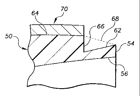
FIG. 2 is an enlarged view of a portion of a rotary bell cup of FIG. 1.
DETAILED DESCRIPTION OF THE INVENTION
FIG. 1 illustrates an electrostatic coating system 10 comprising an
electrostatic applicator 20 having a rotary atomizing device or bell cup 22
that dispenses
charged and atomized coating material toward a target article, not shown in
the drawing,
at an electrical potential, usually electrical ground potential, that is
different from that of
the coating material.
The system comprises a motor 30 or some other rotary drive member that
imparts rotation to the rotary atomizing device 22, as disclosed for example
in the
referenced U.S. Patent No. 5,622,563 entitled "Non-incendive Rotary Atomizer",
which
is assigned commonly herewith and may be referred to for further details.
The rotary applicator 20 is coupled to a high voltage source 40 for direct or
indirect charging of the coating material, also disclosed in the referenced
U.S. Patent No.
5,622,563 entitled "Non-incendive Rotary Atomizer".
In the exemplary embodiment, the bell cup 22 comprises a non-conductive
body member 50 having an inner end 52 and an opposite outer end 54 with an
opening
56 having a generally conical form in the exemplary embodiment disposed
therein and
from which the atomized coating material is dispensed.
The body member 50 is preferably formed of
a resinous or a filled resin material, for example a
glass filled polyetheretherketone (PEEK) or other suitable material,
3

CA 02340273 2001-03-09
"Electrostatic Coating System Atty. Docket No. 967
And Dual Lip Bell Cup Therefor"
some of which are disclosed for example in the referenced U.S. Patent No.
5,622,563 entitled
"Nonincendive Rotary Atomizer", but may also be formed of other non-conductive
materials.
In FIG. 2, the exemplary body member 50 has a generally cylindrical first side
portion 62 with a corresponding first diameter extending from the outer end 54
of the body
member generally axially toward the inner end thereof. In the exemplary
embodiment, the
diameter of the first generally cylindrical side portion 62 of the body member
increases toward
the outer end 54 of the body member so that the first side portion 62 has a
generally conical
shape in correspondence with the generally conical opening 56 formed therein.
The body member 50 also has a generally cylindrical second side portion 64,
with a corresponding second diameter that is greater than the first diameter
of the first
generally cylindrical side portion 62. In FIG. l, the second side portion 64
of the body member
is disposed between the first side portion 62 of the body member and the inner
end 52 thereof.
The body member 50 generally comprises a first lip disposed about the opening
56 thereof proximate or on the outer end 54 thereof, and a second lip disposed
radially
outwardly of the first lip, between the first lip and the inner end 52 of the
body member.
In FIG. 2, the first lip is formed at least partially by the outer end 54 of
the body
member and the first side portion 62 thereof. And the second lip is formed at
least partially
by the second side portion 64 of the body member and a third side portion of
the body member
between the second side portion 64 and the outer end 54 thereof.
In the exemplary embodiment of FIG. 2, the third side portion of the body
member is a generally annular radial portion 66 of the body member located
between and
interconnecting the first and second side portions 62 and 64 thereof.
Alternatively, the third side portion 66 is not necessarily disposed radially
from
the axis of the bell cup as in the exemplary embodiment. The third side
portion 66 may for
example be a generally conical surface extending from the second side portion
64 toward the
outer end 54 of the body member, and in one configuration it extends to the
outer end 54 so
that the first and third side portions form a common surface as indicated by
phantom line 68.
A semiconductive member 70 is disposed on at least a portion of the generally
4

CA 02340273 2001-03-09
"Electrostatic Coating System Atty. Docket No. 967
And Dual Lip Bell Cup Therefor"
cylindrical side portion of the body member 50. The semiconductive member is
preferably a
semiconductive coating or thin film applied to a portion o.f the body member,
as disclosed in
the referenced U.S. Patent No. 5,622,563 entitled "Nonincendive Rotary
Atomizer".
The first lip of the body member is preferably devoid of the semiconductive
coating. In the exemplary embodiment of FIGS. 1 and 2, the semiconductive
coating is
disposed on the second side portion 64 of the body member 50 but not on the
first side portion
62 thereof. The third side portion 66 of the body member in the exemplary
embodiment is also
devoid of the semiconductive coating, but in some alternative embodiments the
third side
portion of the body member may include the semiconductive coating.
A rotary atomizer having the exemplary form and/or the variations thereof
disclosed herein eliminate or substantially reduce the tendency of the charged
and atomized
coating material to wrap back around the side portions thereof, thereby
remarkably improving
coating material transfer efficiency.
The spacing between the first and second lips, for example the difference
between the diameters of the first and second side portions 62 and 64 of the
body member as
represented by the third side portion 66 thereof, and the axial dimension of
the first side
portion 62 of the body member devoid of the semiconductive coating material,
are preferably
selected to optimize the transfer efficiency of the coating material dispensed
from the
atomizing device 22. These particular dimension however are application
specific, depending
for example on the geometry of the article to be coated and the properties of
the coating
material among other factors, and are readily ascertainable without undue
experimentation by
those of ordinary skill in the art based on the disclosure herein.
While the foregoing written description of the invention enables one of
ordinary
skill to make and use what is considered presently to be the best mode
thereof, those of
ordinary skill will understand and appreciate the existence of variations,
combinations, and
equivalents of the specific exemplary embodiments herein. The invention is
therefore to be
limited not by the exemplary embodiments herein, but by all embodiments within
the scope
and spirit of the appended claims.
5

Dessin représentatif
Une figure unique qui représente un dessin illustrant l'invention.
États administratifs

2024-08-01 : Dans le cadre de la transition vers les Brevets de nouvelle génération (BNG), la base de données sur les brevets canadiens (BDBC) contient désormais un Historique d'événement plus détaillé, qui reproduit le Journal des événements de notre nouvelle solution interne.

Veuillez noter que les événements débutant par « Inactive : » se réfèrent à des événements qui ne sont plus utilisés dans notre nouvelle solution interne.

Pour une meilleure compréhension de l'état de la demande ou brevet qui figure sur cette page, la rubrique Mise en garde , et les descriptions de Brevet , Historique d'événement , Taxes périodiques et Historique des paiements devraient être consultées.

Historique d'événement

Description Date
Le délai pour l'annulation est expiré 2018-03-09
Lettre envoyée 2017-03-09
Lettre envoyée 2013-08-07
Accordé par délivrance 2006-10-24
Inactive : Page couverture publiée 2006-10-23
Inactive : Taxe finale reçue 2006-08-09
Préoctroi 2006-08-09
Un avis d'acceptation est envoyé 2006-02-13
Lettre envoyée 2006-02-13
Un avis d'acceptation est envoyé 2006-02-13
Inactive : Approuvée aux fins d'acceptation (AFA) 2005-09-29
Modification reçue - modification volontaire 2005-03-09
Inactive : Dem. de l'examinateur par.30(2) Règles 2004-10-07
Modification reçue - modification volontaire 2004-01-13
Inactive : Dem. de l'examinateur par.30(2) Règles 2003-07-17
Modification reçue - modification volontaire 2003-01-28
Demande publiée (accessible au public) 2001-09-14
Inactive : Page couverture publiée 2001-09-13
Inactive : CIB en 1re position 2001-05-24
Inactive : CIB attribuée 2001-05-24
Inactive : Certificat de dépôt - RE (Anglais) 2001-04-10
Exigences de dépôt - jugé conforme 2001-04-10
Lettre envoyée 2001-04-10
Demande reçue - nationale ordinaire 2001-04-10
Exigences pour une requête d'examen - jugée conforme 2001-03-09
Toutes les exigences pour l'examen - jugée conforme 2001-03-09

Historique d'abandonnement

Il n'y a pas d'historique d'abandonnement

Taxes périodiques

Le dernier paiement a été reçu le 2006-02-22

Avis : Si le paiement en totalité n'a pas été reçu au plus tard à la date indiquée, une taxe supplémentaire peut être imposée, soit une des taxes suivantes :

  • taxe de rétablissement ;
  • taxe pour paiement en souffrance ; ou
  • taxe additionnelle pour le renversement d'une péremption réputée.

Veuillez vous référer à la page web des taxes sur les brevets de l'OPIC pour voir tous les montants actuels des taxes.

Titulaires au dossier

Les titulaires actuels et antérieures au dossier sont affichés en ordre alphabétique.

Titulaires actuels au dossier
FINISHING BRANDS HOLDINGS INC.
Titulaires antérieures au dossier
HAROLD T. ALLEN
Les propriétaires antérieurs qui ne figurent pas dans la liste des « Propriétaires au dossier » apparaîtront dans d'autres documents au dossier.
Documents

Pour visionner les fichiers sélectionnés, entrer le code reCAPTCHA :


Pour visualiser une image, cliquer sur un lien dans la colonne description du document. Pour télécharger l'image (les images), cliquer l'une ou plusieurs cases à cocher dans la première colonne et ensuite cliquer sur le bouton "Télécharger sélection en format PDF (archive Zip)" ou le bouton "Télécharger sélection (en un fichier PDF fusionné)".

Liste des documents de brevet publiés et non publiés sur la BDBC .

Si vous avez des difficultés à accéder au contenu, veuillez communiquer avec le Centre de services à la clientèle au 1-866-997-1936, ou envoyer un courriel au Centre de service à la clientèle de l'OPIC.


Description du
Document 
Date
(aaaa-mm-jj) 
Nombre de pages   Taille de l'image (Ko) 
Dessin représentatif 2001-09-05 1 6
Description 2003-01-28 5 266
Revendications 2003-01-28 4 149
Description 2001-03-09 5 269
Abrégé 2001-03-09 1 16
Revendications 2001-03-09 4 125
Dessins 2001-03-09 1 22
Page couverture 2001-09-07 1 32
Description 2004-01-13 5 262
Revendications 2004-01-13 4 138
Revendications 2005-03-09 4 140
Dessin représentatif 2006-09-29 1 7
Page couverture 2006-09-29 1 34
Courtoisie - Certificat d'enregistrement (document(s) connexe(s)) 2001-04-10 1 113
Certificat de dépôt (anglais) 2001-04-10 1 164
Rappel de taxe de maintien due 2002-11-13 1 109
Avis du commissaire - Demande jugée acceptable 2006-02-13 1 162
Avis concernant la taxe de maintien 2017-04-20 1 178
Correspondance 2006-08-09 1 32