Sélection de la langue

Search

Sommaire du brevet 2341729 

Énoncé de désistement de responsabilité concernant l'information provenant de tiers

Une partie des informations de ce site Web a été fournie par des sources externes. Le gouvernement du Canada n'assume aucune responsabilité concernant la précision, l'actualité ou la fiabilité des informations fournies par les sources externes. Les utilisateurs qui désirent employer cette information devraient consulter directement la source des informations. Le contenu fourni par les sources externes n'est pas assujetti aux exigences sur les langues officielles, la protection des renseignements personnels et l'accessibilité.

Disponibilité de l'Abrégé et des Revendications

L'apparition de différences dans le texte et l'image des Revendications et de l'Abrégé dépend du moment auquel le document est publié. Les textes des Revendications et de l'Abrégé sont affichés :

  • lorsque la demande peut être examinée par le public;
  • lorsque le brevet est émis (délivrance).
(12) Brevet: (11) CA 2341729
(54) Titre français: UNITE DE COMMANDE POUR VANNES DE REGULATION DE FLUIDE
(54) Titre anglais: CONTROL UNIT FOR FLUID CONTROL VALVES
Statut: Périmé et au-delà du délai pour l’annulation
Données bibliographiques
(51) Classification internationale des brevets (CIB):
  • E03D 05/10 (2006.01)
  • E03C 01/05 (2006.01)
(72) Inventeurs :
  • MOORE, DUDLEY (Royaume-Uni)
  • HOPPER, ASHLEY (Royaume-Uni)
(73) Titulaires :
  • ECO-LOGIC (UK) EMPS LIMITED
(71) Demandeurs :
  • ECO-LOGIC (UK) EMPS LIMITED (Royaume-Uni)
(74) Agent: ROBIC AGENCE PI S.E.C./ROBIC IP AGENCY LP
(74) Co-agent:
(45) Délivré: 2009-04-21
(86) Date de dépôt PCT: 1999-08-26
(87) Mise à la disponibilité du public: 2000-03-09
Requête d'examen: 2004-08-23
Licence disponible: S.O.
Cédé au domaine public: S.O.
(25) Langue des documents déposés: Anglais

Traité de coopération en matière de brevets (PCT): Oui
(86) Numéro de la demande PCT: PCT/GB1999/002814
(87) Numéro de publication internationale PCT: GB1999002814
(85) Entrée nationale: 2001-02-26

(30) Données de priorité de la demande:
Numéro de la demande Pays / territoire Date
9818619.0 (Royaume-Uni) 1998-08-26

Abrégés

Abrégé français

L'invention porte sur un appareil de commande comprenant des vannes (5) de régulation de fluide prévues notamment pour alimenter des éléments d'appareils sanitaires (1 et 2). Les vannes possèdent des actionneurs de solénoïde bistables, magnétiques, pouvant être commandés par impulsions, et un circuit (6) de commande commun pouvant commander les actionneurs indépendamment, le circuit de commande et les actionneurs étant commandés par une alimentation électrique locale comprenant une batterie (7) de piles sèches.


Abrégé anglais


Control apparatus including a plurality of fluid control valves (5),
especially for supplying items of sanitary ware (1 and 2). The
valves have magnetic bistable solenoid actuators drivable by pulse signals and
a common control circuit (6) able to drive the actuators
independently and the control circuit and actuators are driven by a local
power supply including a dry cell battery (7).

Revendications

Note : Les revendications sont présentées dans la langue officielle dans laquelle elles ont été soumises.


18
CLAIMS
1. Control apparatus comprising a plurality of fluid control valves,
respective solenoid actuators coupled to the valves and a controller for
supplying control signals to the valves, wherein each solenoid actuator is
a magnetic bistable solenoid actuator for opening and closing the
respective valve, the actuator comprising an armature movable between
two positions corresponding to the open and closed states of the valve
and electromechanical drive means for being driven by respective
electrical drive pulses to move the armature between said positions; the
armature then remaining in the position to which the armature is moved;
the apparatus including for each actuator respective input signal forming
means for controlling the actuators and output signal forming means
connected to the actuator and operable for supplying said respective
electrical drive pulses; a micro processor-based control circuit, the
corresponding input signal forming means and the corresponding output
signal forming means for controlling the valves independently one from
another; input signal supply means for providing control signals to the
control circuit; and a local power supply connected to said control circuit
and said output signal forming means and operable for supplying the
power for driving the control apparatus and said pulses.
2. Control apparatus according to claim 1, wherein the control circuit
comprises a microcontroller connected to said output signal forming
means, and memory means for storing a program and data for

19
causing the microcontroller to respond to said input signal supply means
for independently controlling said valves.
3. Control apparatus according to claim 1, wherein the input signal supply
means comprises one or more control switches for each valve.
4. Control apparatus according to claim 2, wherein the input signal supply
means comprises one or more control switches for each valve.
5. Control apparatus according to claim 1, comprising a manually operable
switch unit connected to the control circuit for causing any of said valves
to open for a selected one of two or more different preset time intervals.
6. Control apparatus according to claim 2, comprising a manually operable
switch unit connected to the control circuit for causing any of said valves
to open for a selected one of two or more different preset time intervals.
7. Control apparatus according to claim 3, comprising a manually operable
switch unit connected to the control circuit for causing any of said valves
to open for a selected one of two or more different preset time intervals.
8. Control apparatus according to claim 5, wherein said manually operable
switch unit comprises a first switch operable via the control circuit for
causing a respective valve to open for a first preset time interval and a
second switch operable via the control circuit for causing the respective
valve to open for a relatively much shorter second preset time interval.

20
9. Control apparatus according to claim 6, wherein said manually operable
switch unit comprises a first switch operable via the control circuit for
causing a respective valve to open for a first preset time interval and a
second switch operable via the control circuit for causing the respective
valve to open for a relatively much shorter second preset time interval.
10. Control apparatus according to claim 7, wherein said manually operable
switch unit comprises a first switch operable via the control circuit for
causing a respective valve to open for a first preset time interval and a
second switch operable via the control circuit for causing the respective
valve to open for a relatively much shorter second preset time interval.
11. Control apparatus according to claim 1 further comprising a switch
unit having a first switch operable via the control circuit for causing a
respective valve to open for a first preset time interval and a second
switch operable via the control circuit for causing the respective valve to
open for a relatively much shorter second preset time interval.
12. Control apparatus according to claim 8, wherein the control circuit
permits the valve to be opened for said second preset time interval only a
predetermined number of times following the opening of the valve for said
first preset time interval.
13. Control apparatus according to claim 9, wherein the control circuit
permits the valve to be opened for said second preset time interval only a
predetermined number of times following the opening of the valve for said
first preset time interval.

21
14. Control apparatus according to claim 10, wherein the control circuit
permits the valve to be opened for said second preset time interval only a
predetermined number of times following the opening of the valve for said
first preset time interval.
15. Control apparatus according to claim 11, wherein the control circuit
permits the valve to be opened for said second preset time interval only a
predetermined number of times following the opening of the valve for said
first preset time interval.
16. Control apparatus according to claim 5, wherein the control circuit
permits a valve to be opened for a second of the preset time intervals only
a predetermined number of times following an opening of a valve for a
first of the preset time intervals.
17. Control apparatus according to claim 8, wherein when any valve is open
the respective second switch is operable via the control circuit for closing
that valve.
18. Control apparatus according to claim 9, wherein when any valve is open
the respective second switch is operable via the control circuit for closing
that valve.
19. Control apparatus according to claim 10, wherein when any valve is open
the respective second switch is operable via the control circuit for closing
that valve.

22
20. Control apparatus according to claim 11, wherein when any valve is open
the respective second switch is operable via the control circuit for closing
that valve.
21. Control apparatus according to claim 5, wherein the control circuit is
responsive to the switch unit for becoming operable to set said control
apparatus into a predetermined control state and for recording a value
representative of a time interval during which the valve is in said state,
and the control circuit then becoming operable in response to said switch
unit for setting said valve into said predetermined control state for a time
equal to about two or more times said time interval.
22. Control apparatus according to claim 6, wherein the control circuit is
responsive to the switch unit for becoming operable to set said control
apparatus into a predetermined control state and for recording a value
representative of a time interval during which the valve is in said state,
and the control circuit then becoming operable in response to said switch
unit for setting said valve into said predetermined control state for a time
equal to about two or more times said time interval.
23. Control apparatus according to claim 7, wherein the control circuit is
responsive to the switch unit for becoming operable to set said control
apparatus into a predetermined control state and for recording a value
representative of a time interval during which the valve is in said state,
and the control circuit then becoming operable in response to said switch

23
unit for setting said valve into said predetermined control state for a time
equal to about two or more times said time interval.
24. Control apparatus according to claim 11, wherein the control circuit is
responsive to the switch unit for becoming operable to set said control
apparatus into a predetermined control state and for recording a value
representative of a time interval during which the valve is in said state,
and the control circuit then becoming operable in response to said switch
unit for setting said valve into said predetermined control state for a time
equal to about two or more times said time interval.
25. Control apparatus according to claim 8, wherein the control circuit is
responsive to the switch unit for becoming operable to set said control
apparatus into a predetermined control state and for recording a value
representative of a time interval during which the valve is in said state,
and the control circuit then becoming operable in response to said switch
unit for setting said valve into said predetermined control state for a time
equal to about two or more times said time interval.
26. Control apparatus according to claim 9, wherein the control circuit is
responsive to the switch unit for becoming operable to set said control
apparatus into a predetermined control state and for recording a value
representative of a time interval during which the valve is in said state,
and the control circuit then becoming operable in response to said switch
unit for setting said valve into said predetermined control state for a time
equal to about two or more times said time interval.

24
27. Control apparatus according to claim 10, wherein the control circuit is
responsive to the switch unit for becoming operable to set said control
apparatus into a predetermined control state and for recording a value
representative of a time interval during which the valve is in said state,
and the control circuit then becoming operable in response to said switch
unit for setting said valve into said predetermined control state for a time
equal to about two or more times said time interval.
28. Control apparatus according to claim 1, said power supply comprising a
dry cell battery.
29. Apparatus comprising a plurality of sanitary ware units, corresponding
water control valves connected to the units, respective solenoid actuators
coupled to the valves and a controller connected to the actuators,
wherein each solenoid actuator is a magnetic bistable solenoid actuator
for opening and closing the respective valve, each valve having a
respective switch unit for controlling the respective valve independently
from the other valves, and output signal means for driving the respective
actuators, a single microprocessor-based control circuit connected to the
water control valves for responding to the switch unit to control the
actuators, a power supply coupled to the control circuit for supplying
power to operate the control circuit and, via the control circuit,
energising said control valves.
30. Apparatus according to claim 29, wherein each switch unit comprises
two or more switches for causing the respective valve to open for
respective predetermined time intervals.

25
31. Apparatus according to claim 29, further including temperature sensing
means for sensing the temperature of water supplied by the valves and
for providing an over-temperature signal to the controller.
32. Apparatus according to claim 30, further including temperature sensing
means for sensing the temperature of water supplied by the valves and
for providing an over-temperature signal to the controller.
33. Apparatus according to claim 29 wherein the power supply is operable
for being driven by mains or other electrical supply and further includes
a dry cell battery operable as a back-up power supply.
34. Apparatus according to claim 30 wherein the power supply is operable
for being driven by mains or other electrical supply and further includes
a dry cell battery operable as a back-up power supply.
35. Apparatus according to claim 34 wherein the power supply is operable
for being driven by mains or other electrical supply and further includes
a dry cell battery operable as a back-up power supply.

Description

Note : Les descriptions sont présentées dans la langue officielle dans laquelle elles ont été soumises.


CA 02341729 2008-06-11
1
CONTROL UNIT FOR FLUID CONTROL VALVES
The invention relates to a control unit for conLrolling electrical apparatus,
for
example, an electromechanical device such as a solenoid operated fluid control
valve. While the control unit is capable of a wide variety of uses it is seen
to
good effect in the control of a number of valves supplying a fluid such as
water
to a tap, shower unit, toilet or any combination; or the like. Thus, more
particularly, but not exclusively, the invention relates to a toilet facility
with a
control unit and valves arranged for supplying water to respective items of
sanitary ware; for example, a shower, wash basin and water closet (WC) or
several showers (say).
Electrically controlled vi-ater valves have utility in plumbing installations
and
toilet facilities where water saving is particularly important, where misuse
is
likely, or simply for safety and ease of use, say in a toilet faciIity
intended for
use by an elderly or disabled person.
Electrical battery powered valves are preferred for safety and ease of
installation.
European Patent No. EP 0574372 A 1 discloses control apparatus comprising a
plurality of fluid control valves, respective solenoid actuators coupled to
the
valves and a controller for supplying control signals to the valves.

CA 02341729 2006-10-26
2
According to one aspect of the invention, there is provided a control
apparatus
comprising a plurality of fluid control valves, respective solenoid actuators
coupled to the valves and a controller for supplying control signals to the
valves,
wherein each solenoid actuator is a magnetic bistable solenoid actuator for
opening and closing the respective valve, the actuator comprising an armature
movable between two positions corresponding to the open and closed states of
the valve and electromechanical drive means for being driven by respective
electrical drive pulses to move the armature between said positions; the
armature then remaining in the position to which the armature is moved; the
apparatus including for each actuator respective input signal forming means
for
controlling the actuators and output signal forming means connected to the
actuator and operable for supplying said respective electrical drive pulses; a
micro processor-based control circuit, the corresponding input signal forming
means and the corresponding output signal forming means for controlling the
valves independently one from another; input signal supply means for providing
control signals to the control circuit; and a local power supply connected to
said
control circuit and said output signal forming means and operable for
supplying
the power for driving the control apparatus and said pulses.
The apparatus to be described conserves power by using bistable actuators and
providing a simple controller that independently controls respective input
switch/output drive actuator circuits.
The control circuit means may comprise a microcontroller connected to said
output signal forming means; and memory means for storing a programme and
data for causing the microcontroller to respond to said input signal supply
means
for independently controlling said valves. The input signal supply means may
comprise one or more control switches for each control device.

CA 02341729 2006-10-26
3
Advantageously the control apparatus comprises manually operable switch
means connected to the control circuit means for causing any of said valves to
open for a selected one of two or more difl'erent preset time intervals.
The switch means may comprise a first switch operable via the control means
for causing a respective valve to open for a first preset time interval and a
second switch operable via the control means for causing that valve to open
for
a relatively much shorter second preset time interval.
Advantageously the control circuit means permits the valve to be opened for
said second preset time interval only a predetermined number of times
following the opening of the valve for said first preset time interval.
When any valve is open, the respective second switch may become operable via
the control circuit means for closing that valve.
Preferably, the control circuit means is responsive to the switch means for
becoming operable to set said device into a predetermined control state and
for
recording a value representative of a time interval during which the valve is
in
said state, and the control circuit then becoming operable in response to said
switch means for setting said valve into said predetermined control state for
a
time equal to two or more times said time interval.
According to another aspect of the invention, there is provided an apparatus
comprising a plurality of sanitary ware units, corresponding water control
valves

CA 02341729 2006-10-26
4
connected to the units, respective solenoid actuators coupled to the valves
and
a controller connected to the actuators, wherein each solenoid actuator is a
magnetic bistable solenoid actuator for opening and closing the respective
valve, each valve having a respective switch unit for controlling the
respective
valve independently from the other valves, and output signal means for driving
the respective actuators, a single microprocessor-based control circuit
connected to the water control valves for responding to the switch unit to
control
the actuators, a power supply coupled to the control circuit for supplying
power
to operate the control circuit and, via the control circuit, energising said
control
valves.
Each switch means may comprise two or more switches for causing the
respective valve to open for respective predetermined time intervals.
According to yet another aspect of the invention there is provided a control
unit
arranged to control the opening and closing of at least two valves such as
latching solenoid valves to transfer fluid to respective outlets from a common
source or separate sources of said fluid, the control unit comprising:
one or more manually operable switches for each valve to initiate opening
and closing of the valve;

WO 00/12830 PCT/GB99/02814
- timing means arranged to control the time period for which each valve
is open;
- override means to cut short the predetermined time period;
- a top up/off switch arranged to open one or more valves for a limited
number of time cycles and, as a secondary function, for closing said
valves if they are open;
- lock-out switch means operable for closing the valves for predetermined
intervals;
- a lock out key switch to close the valves; and
- a dry cell battery power source to provide power for the control unit
and, via the control unit, for the valves.
Preferably the unit includes temperature control means.
Preferably the control unit comprises two channels each to control a
respective
valve, each channel having a number of switch inputs, some of these inputs
can be time programmed while another of which is enabled only when one of
the other inputs is enabled. This other input is arranged to override the
others when the flow valve is open or to augment the flow valve if at the time
of
energisation the valve is shut.
CA 02341729 2001-02-26

WO 00/12830 PCT/GB99/02814
6
One or more auxiliary channels may be present and will then be arranged to
have a simple on/off switch function.
By splitting the power load into a number of switches each of which is
energised according to the circumstances the power required is reduced and a
single dry cell (or a few) can be used for a plurality of valves.
The design of the device to be described is such that it can be programmed to
give various ways of operating and to set up different chosen time values and
such.
In order that the invention may be well understood it will now be described by
way of example, with reference to the accompanying drawings, in which:
Figure 1 is a diagram of a toilet facility;
Figure 2 is a simplified circuit diagram of a control unit;
Figure 3 is a plan view of a circuit board of the control unit;
Figure 4 is a circuit diagram of the control unit; and
Figure 5 is a simplified diagram of a valve with a bistable solenoid
actuator.
CA 02341729 2001-02-26

WO 00/12830 PCT/GB99/02814
7
The toilet facility of Figure 1 comprises a WC (water closet) 1 and a
washbasin
2 with hot and cold taps (faucets) 3. The WC 1 and the taps 3 are supplied
with water via respective pipes 4 each including an electrically operable shut-
off valve S.
As shown in the diagram of Figure 5, each shut-off valve 5 comprises a
bistable solenoid actuator 100 for switching the valve 5 between its on and
off
states. The bistable solenoid actuator has an armature 101 pivotably
mounted at end 110 to a support 111, an electromagnetic drive coil 102 and a
permanent holding magnet 103. The armature 101 is coupled to the valve
member (as indicated by dashed line 109) of the valve 5 and is movable
between first and second limit positions 104 and 105 corresponding to the off
and on states of the valve. If the armature 101 is at the second limit
position
105 it remains held in this position by the holding magnet 103. If the
armature is at the first position 104, it remains there because the holding
magnet is not strong enough on its own to cause the armature to move.
However, by applying a first pulse signal to the electromagnetic coil, the
holding magnet 103 is supplemented by the field due to the electromagnetic
coil 102 and then the armature does move to the second limit position 105.
To release the armature from being held by the holding magnet, a reverse
polarity pulse is applied to the coil. This not only overcomes the attractive
force of the holding magnet but actually drives the solenoid armature back to
its first limit position 104. Thus, the solenoid actuator 100 is operated,
i.e.
driven between its valve open and valve closed positions by shortpulses only
and no position-maintaining drive signal need be supplied.
CA 02341729 2001-02-26

WO 00/12830 PCT/GB99/02814
8
The armature 108 may be coupled to spring means 106 or another permanent
magnet 107 arranged to maintain it gently held back to its first limit
position
104 or there may be no such spring means and other permanent magnet.
Each valve may be of the kind in which a valve member is moved to shut off or
release the flow of water directly or, as shown in the drawings the valve may
have one or more stages 108 of indirect or "servo" control, e.g. in which the
valve member controls a small bleed hole in a diaphragm or the like so
allowing or releasing a pressure build-up which in turn results in movement of
the diaphragm and control of the water flow through the valve.
The valves are controlled by a microprocessor based control unit 6 powered by
a lithium manganese dioxide dry cell battery 7.
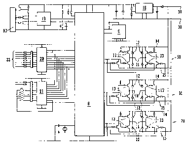
As shown in Figures 2 to 4, each control unit 6 comprises a microcontroller 8
and an electrically erasable programmable read-only memory (EEPROM) 9
connected to the microcontroiler and containing the program and data for the
microcontroller 8.
The pulse signals for driving the valves are supplied by respective driver
circuits 10. Each driver circuit has two output terminals 11 connected to the
respective valve. The output terminals 11 in each drive circuit are connected
via diodes 12 and via NPN/PNP transistor pairs 13 to high and low supply
rails 14 and 15 respectively, connected to the battery 7. The microcontroller
8
and other semiconductor devices in the control unit 6 are driven by the
battery 7 via a constant voltage regulator 16.
CA 02341729 2001-02-26

CA 02341729 2006-10-26
9
The microcontroller 8 is also coupled via microprocessor 19 and connector
unit 80 to a sensor/display unit 17. The function of the microprocessor 19 is
to receive the temperature indicative signals from the temperature sensor of
the unit 17, to process these signals and compare them with an appropriate
over-temperature threshold. The microprocessor then supplies an automatic
over-temperature shut down signal to the unit 3. The sensor/display unit 17
may comprise a commercially available pre-r.nade unit, basically a digital
thermometer, perhaps with adaptation as appropriate. The sensor/display
unit may, of course, comprise yet another microcontroller for running the
digital display.
The control unit also has a switch interface circuit 13 which comprises two
eight bit registers 20 and 21 having outputs multiplexed into respective
signal
inputs of the microcontroller 8.
The register 20 is settable in accordance with eight push button switches 22
comprises in a control panel 23 while register 21 reflects the state of five
DIP
switches 23 and a push button switch mounted on the printed circuit board of
the control unit 8. The register 21 is also connected to input terminals 25
for
receiving an optional external input signal and an optional key switch (not
shown).
The circuit board (PCB) of the control unit has terminals 30 for connection to
a
6v dry cell battery such as lithium mangmese dioxide battery. The
microcontroller 8 pin IC with two sets of pins leading to respective output
sub-
circuits (50, 60 and 70) each to control a respective valve. The master IC

CA 02341729 2006-10-26
is also connected to button input chip 20 and via chip 21 to an external I/P
and key switch terminals 25, the DIP switches 23, a push-button and to the
connector 80 for the temperature sensor/display module circuit 17. Chip 20
is coupled to connector 90 for linking to switches 22 on panel 23.
The circuit board of Figure 3 is the main control board for a system
incorporating valves V 1, V2, V3 and so on, e.g. for tap, shower and W.C.
control.
The board can independently control up to 3 latching solenoid valves, V1, V2,
V3. These open' or close according to manual operation of switches not
shown. The valve `open' times can be set to any value within a wide range, but
the valves can also be closed early at any time. There is provision for a key
operated switch 100 that will act as a LOCKOUT, whereby all valves will be
closed and all switch inputs will be inhibited during its operation.
Certain switch inputs have additional attributes such as TOP UP/STOP
function and the third channel can be closed if the temperature sensor circuit
17 detects a temperature beyond the set high lirnit. Functions can be enabled
or disabled as desired.
If required, to help prevent overfilling, restrict water use or provide a
safety
control, a`disable' time can be provided so that after a fill has taken place,
no
further fills can be started for a set periods (channels 1 and 2 only). The
TOP
UP/ STOP continues to be available, subject to a maximum of 5 operations.

WO 00/12830 PCT/GB99/02814
11
VALVE CHANNELS 1 AND 2
These are two separate, but identical channels. Each channel has 4 switch
inputs, one of which may be designated as TOP UP/STOP, and each switch
can have its own respective FILL TIME programmed with it.
For the first 3 switch inputs, the valve will open for the pre-programmed
period, then close. In addition, the 3 switches themselves can be set either,
(a)
to be disabled whilst filling is taking place or, (b) to allow a second
operation to
close the valve.
If the fourth switch is set to be TOP UP/STOP, it will only be enabled
following
a fill operation commenced by one of the first 3 switches. Whilst the valve is
open, this switch will act as a STOP, closing the valve and cancelling the
current fill time. Whilst the valve is closed, the switch becomes TOP UP arnd
a
maximum of 5 operations are allowed before this switch becomes disabled.
If the fourth switch is set to be ON/OFF, it will always be available to
commence a fill, and then a second push will close the valve.
If the unit is set by dipswitches to give a DELAY TIME, switches 1 to 3 will
be
disabled for this time period following a fill, but the TOP UP/ STOP will
remain
enabled.
VALVE CHANNEL 3
This channel has one switch associated with it, connected to the Ext I/P
terminals, and would usually be used for shower control. This channel can
have its own fill time programmed with it. Operating the switch will cause the
CA 02341729 2001-02-26

WO 00/12830 PCT/GB99/02814
12
valve to open for a preset period, whilst operating the switch a second time
will
cause the valve to close.
TEMPERATURE MODULE
The module senses and displays the water temperature at a suitable point
and if the optional auto-close module is fitted, when the temperature reaches
43oC or above the valve will close. The valve cannot be opened whenever the
temperature exceeds this setting.
LOCKOUT KEYSWITCH
The lockout keyswitch can be used to prevent unauthorised personnel from
operating the unit. Whilst in the lockout condition, all valves will be closed
and all switch inputs become disabled.
SETUP
From stages 1 and 2 below, choose the fill times and mode of operation
required. The unit will normally be supplied with `default' settings, whereby
all
the fill times are set to zero so the unit will not respond to any switch
inputs
until it has been setup.
The unit can be retumed to `default' settings whereby all fill times are set
to
zero by implementing stage 3.
All settings will remain in the board's memory even if the battery is
disconnected for prolonged periods.
CA 02341729 2001-02-26

WO 00/12830 PCT/GB99/02814
13
1 Programming fill time is the same for each switch, and must be followed
for each and every one used:
i) Ensure the battery is connected and that the LOCKOUT is off.
ii) Press and release the PROG button (any open valves will close).
iii) Determine what run time or fill time is required for the switch to
be programmed. Press that fill switch - the respective valve will
open. Once the desired run time has elapsed (or the fill level is
achieved), press the same fill switch again - the valve will close.
iv) Wait 2 seconds to allow the memory to be updated.
v) Repeat steps (ii) to iv) for all other fill switches.
2. Programming each switch for ON or ON/OFF operation:
ON mode - once fill is started, subsequent switch
operations are ignored
ON/OFF mode - alternate switch operations open and close
the valve.
The unit will normally be supplied with each of the first 3 switches on
channels 1 and 2 set for ON/OFF operation and the fourth switch as
TOP UP/STOP. If required, the first 3 switches can be reprogrammed
CA 02341729 2001-02-26

WO 00/12830 PCT/GB99/02814
14
for ON mode operation, and the fourth switch can be reprogrammed as
ON/OFF.
For channel 3, only ON/OFF is provided and cannot be altered.
Check the current setting for each switch by trial - only reprogramme if
an alternative setting is required.
(i) Ensure the battery is connected and that LOCKOUT is off.
(ii) Press and release the PROG button (any open valves will close).
(iii) Operate the LOCKOUT then return to the `off' position.
(iv) Press the appropriate switch to be programmed.
(v) Wait 2 seconds to allow the memory to be updated.
3. Programming all switches disabled.
(i) Ensure the battery is connected and that the LOCKOUT is off.
(ii) Press PROG and hold down for at least 3 seconds (any open
valves will close).
(iii) Wait 2 seconds to allow the memory to be updated.
CA 02341729 2001-02-26

WO 00/12830 PCT/GB99/02814
4. Dipswitch settings
These can be changed at any time, but it is recommended to leave this
until all the above programming steps have been made and the correct
fill times and modes have been checked.
There are 5 dipswitches that operate as detailed below. The dipswitch
is `on' when it is in the up position and `off when it is down.
Switches
Channels 1 & 2 1 2 3 4 DELAY TIME
off off off off ZERO
on off off off 5 minutes
off on off off 10 minutes
on on off off 15 minutes
off off on off 20 minutes
on off on off 25 minutes
off on on off 30 minutes
on on on off 35 minutes
off off off on 40 minutes
on off off on 45 minutes
off on off on 50 minutes
on on off on 55 minutes
off off on on 60 minutes
on off on on 65 minutes
off on on on 70 minutes
on on on on 75 minutes
CA 02341729 2001-02-26

WO 00/12830 PCT/GB99/02814
16
Switch
off fill time as programmed
fill time as programmed x 10
Channel 3 (Shower Time) 5
This setting is ideal to reduce
waiting time when programming
on channel 3 fill time.
EXAMPLE
Say a shower time of 5 minutes (300 seconds) is required, this could be
achieved in two ways.
a) Follow setup stage 1, waiting the full 5 minutes between pressing the
fill switch for the open and close times. Then leave dipswitch pole 5 off
b) Follow setup stage 1, but wait just 30 seconds between pressing the fill
switch for the open and close times. Put dipswitch pole 5 on (10 x
30 = 300 seconds).
It will be seen that the control unit has been constructed to provide a
multiplicity of functions for a plurality of valves, all powered from a single
dry
cell battery.
The invention is not just applicable to toilet facilities, plumbing
instaIlations or
even fluid control valves. Instead, a control unit as described may be used in
CA 02341729 2001-02-26

WO 00/12830 PCT/GB99/02814
17
other situations. In particular, the method described at b) above for
programming a time value into a control unit is generally useful.
The power supply used in the described embodiments could be adapted for
mains operation, or for receiving power from a local supply such as a large
battery, but with back-up from the dry cell battery mentioned. The battery
could be rechargeable and arranged to be rechargeable whilst in situ or
elsewhere.
CA 02341729 2001-02-26

Dessin représentatif
Une figure unique qui représente un dessin illustrant l'invention.
États administratifs

2024-08-01 : Dans le cadre de la transition vers les Brevets de nouvelle génération (BNG), la base de données sur les brevets canadiens (BDBC) contient désormais un Historique d'événement plus détaillé, qui reproduit le Journal des événements de notre nouvelle solution interne.

Veuillez noter que les événements débutant par « Inactive : » se réfèrent à des événements qui ne sont plus utilisés dans notre nouvelle solution interne.

Pour une meilleure compréhension de l'état de la demande ou brevet qui figure sur cette page, la rubrique Mise en garde , et les descriptions de Brevet , Historique d'événement , Taxes périodiques et Historique des paiements devraient être consultées.

Historique d'événement

Description Date
Le délai pour l'annulation est expiré 2012-08-27
Lettre envoyée 2011-08-26
Inactive : Correspondance - TME 2010-08-10
Accordé par délivrance 2009-04-21
Inactive : Page couverture publiée 2009-04-20
Inactive : Taxe finale reçue 2009-01-30
Préoctroi 2009-01-30
Un avis d'acceptation est envoyé 2008-08-04
Lettre envoyée 2008-08-04
Un avis d'acceptation est envoyé 2008-08-04
Inactive : Pages reçues à l'acceptation 2008-06-11
Inactive : Lettre officielle 2008-05-09
Inactive : Approuvée aux fins d'acceptation (AFA) 2008-03-31
Modification reçue - modification volontaire 2008-01-10
Inactive : Dem. de l'examinateur par.30(2) Règles 2007-07-10
Inactive : Lettre officielle 2007-03-27
Inactive : Grandeur de l'entité changée 2007-03-27
Inactive : Paiement correctif - art.78.6 Loi 2007-02-01
Inactive : Supprimer l'abandon 2007-01-12
Inactive : Abandon. - Aucune rép dem par.30(2) Règles 2006-10-26
Inactive : Dem. de l'examinateur par.30(2) Règles 2006-04-26
Inactive : Demande ad hoc documentée 2004-09-16
Lettre envoyée 2004-09-16
Inactive : Demande ad hoc documentée 2004-09-16
Inactive : RE du <Date de RE> retirée 2004-09-16
Inactive : Paiement - Taxe insuffisante 2004-09-15
Inactive : Grandeur de l'entité changée 2004-09-15
Inactive : Paiement - Taxe insuffisante 2004-09-10
Requête d'examen reçue 2004-08-23
Exigences pour une requête d'examen - jugée conforme 2004-08-23
Toutes les exigences pour l'examen - jugée conforme 2004-08-23
Inactive : Grandeur de l'entité changée 2003-09-04
Lettre envoyée 2001-07-12
Inactive : Transfert individuel 2001-06-05
Inactive : Page couverture publiée 2001-05-23
Inactive : CIB en 1re position 2001-05-17
Inactive : Lettre de courtoisie - Preuve 2001-05-08
Inactive : Notice - Entrée phase nat. - Pas de RE 2001-05-01
Demande reçue - PCT 2001-04-24
Demande publiée (accessible au public) 2000-03-09

Historique d'abandonnement

Il n'y a pas d'historique d'abandonnement

Taxes périodiques

Le dernier paiement a été reçu le 2008-08-25

Avis : Si le paiement en totalité n'a pas été reçu au plus tard à la date indiquée, une taxe supplémentaire peut être imposée, soit une des taxes suivantes :

  • taxe de rétablissement ;
  • taxe pour paiement en souffrance ; ou
  • taxe additionnelle pour le renversement d'une péremption réputée.

Les taxes sur les brevets sont ajustées au 1er janvier de chaque année. Les montants ci-dessus sont les montants actuels s'ils sont reçus au plus tard le 31 décembre de l'année en cours.
Veuillez vous référer à la page web des taxes sur les brevets de l'OPIC pour voir tous les montants actuels des taxes.

Historique des taxes

Type de taxes Anniversaire Échéance Date payée
Taxe nationale de base - petite 2001-02-26
Enregistrement d'un document 2001-06-05
TM (demande, 2e anniv.) - petite 02 2001-08-27 2001-08-24
TM (demande, 3e anniv.) - petite 03 2002-08-26 2002-08-23
TM (demande, 4e anniv.) - générale 04 2003-08-26 2003-08-21
Requête d'examen - petite 2004-08-23
TM (demande, 5e anniv.) - petite 05 2004-08-26 2004-08-24
TM (demande, 6e anniv.) - petite 06 2005-08-26 2005-08-24
TM (demande, 7e anniv.) - générale 07 2006-08-28 2006-08-25
2007-02-01
TM (demande, 8e anniv.) - générale 08 2007-08-27 2007-08-24
TM (demande, 9e anniv.) - générale 09 2008-08-26 2008-08-25
Taxe finale - générale 2009-01-30
TM (brevet, 10e anniv.) - générale 2009-08-26 2009-08-26
TM (brevet, 11e anniv.) - générale 2010-08-26 2010-08-26
Titulaires au dossier

Les titulaires actuels et antérieures au dossier sont affichés en ordre alphabétique.

Titulaires actuels au dossier
ECO-LOGIC (UK) EMPS LIMITED
Titulaires antérieures au dossier
ASHLEY HOPPER
DUDLEY MOORE
Les propriétaires antérieurs qui ne figurent pas dans la liste des « Propriétaires au dossier » apparaîtront dans d'autres documents au dossier.
Documents

Pour visionner les fichiers sélectionnés, entrer le code reCAPTCHA :


Pour visualiser une image, cliquer sur un lien dans la colonne description du document. Pour télécharger l'image (les images), cliquer l'une ou plusieurs cases à cocher dans la première colonne et ensuite cliquer sur le bouton "Télécharger sélection en format PDF (archive Zip)" ou le bouton "Télécharger sélection (en un fichier PDF fusionné)".

Liste des documents de brevet publiés et non publiés sur la BDBC .

Si vous avez des difficultés à accéder au contenu, veuillez communiquer avec le Centre de services à la clientèle au 1-866-997-1936, ou envoyer un courriel au Centre de service à la clientèle de l'OPIC.


Description du
Document 
Date
(aaaa-mm-jj) 
Nombre de pages   Taille de l'image (Ko) 
Dessin représentatif 2001-05-22 1 5
Revendications 2001-02-25 4 170
Dessins 2001-02-25 4 80
Description 2001-02-25 18 605
Abrégé 2001-02-25 1 55
Revendications 2006-10-25 8 264
Description 2006-10-25 17 531
Dessins 2006-10-25 4 73
Revendications 2008-01-09 8 258
Dessin représentatif 2008-04-28 1 12
Description 2008-06-10 17 531
Rappel de taxe de maintien due 2001-04-30 1 111
Avis d'entree dans la phase nationale 2001-04-30 1 193
Courtoisie - Certificat d'enregistrement (document(s) connexe(s)) 2001-07-11 1 112
Rappel - requête d'examen 2004-04-26 1 116
Accusé de réception de la requête d'examen 2004-09-15 1 185
Avis du commissaire - Demande jugée acceptable 2008-08-03 1 164
Avis concernant la taxe de maintien 2011-10-06 1 170
Correspondance 2001-04-30 1 23
PCT 2001-02-25 16 591
Correspondance 2001-06-04 2 81
Taxes 2003-08-20 1 31
Taxes 2001-08-23 1 31
Taxes 2002-08-22 1 30
Taxes 2004-08-23 1 27
Correspondance 2004-11-30 2 62
Correspondance 2005-02-01 2 57
Taxes 2005-08-23 1 26
Taxes 2006-08-24 1 34
Correspondance 2007-03-26 1 15
Taxes 2007-08-23 1 45
Correspondance 2008-05-08 1 21
Taxes 2008-08-24 1 42
Correspondance 2009-01-29 2 52
Taxes 2009-08-25 1 32
Correspondance 2010-08-09 1 47
Taxes 2010-08-25 1 38
Correspondance 2011-10-06 1 87