Note : Les descriptions sont présentées dans la langue officielle dans laquelle elles ont été soumises.
CA 02342056 2001-03-26
-1-
FEMORAL HIP PROSTHESIS
This invention relates to a prosthetic femoral component of the
type which is applied without a stem in the medullary canal, which is
considered to be conservative and bone sparing.
For present purposes a conservative femoral hip prosthesis is a
prosthesis which leaves sufficient bone in place for it to be
eventually replaced by a more conventional femoral hip prosthesis with
a medullary stem normally intended for primary (non-revision)
application. A bone-sparing femoral hip prosthesis is one which limits
the removal of viable bone by conserving some of the femoral head,
removing only sufficient bone to resect the diseased tissue and to
effect a satisfactory anchorage.
The use of femoral hip prostheses which function without a stem
in the medullary canal date from the first total hip prosthesis
reported by Wyles in 1937. This hip prosthesis was fitted following a
high resection of the femoral head and was stabilised with a straight
stem which passed along the femoral neck and out below the greater
trochanter, where it was attached to a bone plate secured on the
lateral cortex of the femur. The Wyles hip restored the femoral head
with a bearing diameter deliberately smaller than the natural femoral
head it was replacing. Only six cases were ever performed using this
device since the clinical outcome was not impressive.
Another femoral hip prosthesis design following that of Wyles
was the Judet prosthesis, developed in France and used in the period
1945-55. A high neck resection was used with this prosthesis, which
attempted to restore the femoral head to its natural diameter for use
as a hemiarthroplasty. The prosthesis comprised an acrylic (low
modulus) head and a short straight stem which passed along the femoral
neck. The prosthetic head included a trough around the stem attachment
to the head, which was used to seat and locate the prosthesis on the
prepared proximal end of the femoral neck. Early breakage caused the
stem to be given a stainless steel core support. Later failures saw
the device breaking out through the inferior femoral neck. All
CA 02342056 2001-03-26
_2_
versions of this prosthesis suffered from premature wear of the acrylic
head.
High neck resections, i.e. those conserving the femoral neck,
were also used by femoral hip prostheses with stems passing into the
medullary canal, notably the designs of Pipino (1978) and Freeman
(1985). These hip prostheses were implanted both cement-free and with
cement, but did not attempt to restore the femoral head to its natural
diameter, being used as total hip replacements with a head of smaller
dimensions. Since these femoral hip replacements do place a stem in
the medullary canal, they are not considered to be conservative,
although the stem on the Pipino design was very short.
Designs of femoral hip prostheses which have attempted to
secure the replacement of the femoral head without a stem in the
medullary canal follow the design of Vincent and Munting reported in
1982, which is still in clinical use. With this design, a portion of
the femoral neck is preserved and shaped with a notch to provide
seating for the implant. The prosthesis is used as a total hip
replacement and replaces part of the femoral neck and the femoral head
with a head of smaller diameter than the natural head. The prosthesis
is used uncemented and is fixed with a large screw through the lateral
cortex into the body of the prosthesis. The prosthesis is intended to
sit on the remaining cortex of the neck and is stabilised by fins
parallel to the axis of the neck which pass into the remaining
diaphyseal cancellous bone. The bone engaging surfaces are provided
with a hydroxyapatite coating to promote bone ongrowth to augment
fixation.
The Vincent-Munting prosthesis is considered to be conservative
but not bone sparing, according to the definitions given above. The
only type of femoral hip prosthesis which has been developed which is
conservative and bone sparing is the femoral cap used in prostheses
such as the ICLH (Freeman, 1973), the THARIES (Amstutz, 1976), the
Wagner (Wagner, 1973), the Zephyr (Aubriot, 1977) and the Gerard
(Gerard, 1975). This type of prosthesis comprised a metal cap with a
part-spherical external form and different internal forms and was used
CA 02342056 2001-03-26
-3-
both cemented and uncemented. The bearing surface of the femoral cap
was always near to anatomical size, therefore the cap could be used as
a hemiarthroplasty. Mechanical loosening through stress concentration
at the bone interface were reported as well as resorption of epiphyseal
bone beneath the cap. The cause of the bone resorption was associated
with disruption of the blood supply to regions of bone as a result of
the surgical technique. Often the cap was used to articulate with a
polyethylene liner in the acetabulum, and with this an additional
failure mode of osteolysis at the bone interface with the prosthesis
was caused by the ingress of polyethylene debris.
A development of the femoral cap design was the inclusion of a
short stem to the cap. Examples of such designs include the TARA hip
(1970's) and, more recently the McMinn hip (1990's).
An alternative design approach for the femoral cup is presented
in European Patent Specifications EP 0 094 829 and EP 0 176 188, which
describe a stemless femoral hip prosthesis intended to load the bone
naturally. The first design required the resection of most the femoral
head and part of the neck, the later design required only the resection
of the proximal portion of the femoral head up to the epiphyseal scar
plate. In the later design, a low modulus material between the bone
and the femoral cap was used to transfer load with a more physiological
force distribution onto the trabecular structure of the proximal
femur. In practice, too little bone was removed for adequate surgical
exposure of the acetabulum without excessive soft tissue damage.
Furthermore, controlled exposure of the three-dimensional epiphyseal
scar plate proved to be too complex and the design was never developed
into an implant.
Cemented intramedullary fixation of femoral hip prostheses has
now approximately 30 years successful clinical results and is the
benchmark against which new designs of hip implants are assessed.
Early problems of implant fracture, corrosion, cement mantle integrity
and excessive bearing wear have now been largely resolved and the main
problem which limits the life expectancy of conventional femoral hip
prostheses is aseptic loosening. Nevertheless, since premature failure
CA 02342056 2001-03-26
-4-
of the reconstruction may occur due to loosening, eventual revision of
the prosthesis, particularly when used for younger patients (under 65),
must be considered.
The revision of cemented stemmed femoral hip prostheses is
challenging, particularly a as result of needing to remove all the
cement. In fact, cementless stems with intramedullary fixation have
been developed to simplify the revision procedure. Such devices
require increased surgical precision compared with cemented hip
prostheses and have their own failure modes such as pain, loosening and
subsidence.
It is the likelihood of subsequent revision for the younger and
more active patient which makes a conservative, and indeed bone
sparing, femoral hip prosthesis an attractive option. In theory, such
a device may be revised with a conventional primary stemmed hip
prosthesis without the need for bone grafting or other augmentation.
Indeed, there is no reason why conservative hip designs could not be at
least as safe and efficacious as intramedullary stemmed hip designs.
However, attempts so far to develop a conservative, bone sparing
femoral hip prosthesis have encountered significantly worse results due
to premature loosening of the femoral component (and acetabular
component).
The present design seeks to provide a conservative, bone
sparing femoral hip prosthesis that addresses the problems encountered
by previous designs. The prosthesis includes an insert portion which
is designed to control the transfer of load to the femur so as to avoid
stress concentration at the bone interface. The insert portion is
sized so that it replaces all the epiphyseal bone thereby minimising
the risk of bone resorption due to disrupted blood supply. It is also
tapered so as to self seal under load so as to restrict the ingress of
debris leading to osteolysis.
In addition to addressing the deficiencies of previous designs,
the present design seeks to simplify the surgical technique so as to
achieve better reproducibility of results and to minimise the trauma
CA 02342056 2001-03-26
-5-
(e.g. loss of blood, post-operative infection) associated with the
procedure.
Hip replacement is usually performed with a large exposure.
Early post-operative infection is no longer a significant problem, but
the time to heal such a major wound is significant. Some surgeons now
implant conventional stemmed devices with as small an incision as they
possibly can. After the femoral head and neck have been removed, only
narrow tools are needed to prepare the femoral canal and there is easy
access to the acetabulum. However, the bone sparing femoral hip
prosthesis designs generally necessitate reverting to a wider exposure
for two reasons. Firstly, preparation of the outside of the femoral
head involves bulkier instruments. Secondly, the femoral head
obstructs access to the acetabulum. More cutting of soft tissues
attaching the femur to the pelvis is needed to manoeuvre the femoral
head out of the way.
The present invention is intended to provide a femoral hip
prosthesis which can be employed in a method of fitting which includes
cutting away the natural femoral head to expose the circular cross-
section of the neck at the base of or at a mid point of the head. This
allows much improved access to the acetabulum, thereby reducing the
length of the required incision and minimising the soft tissue
dissection necessary to allow the remaining femoral head to be levered
out of the way. The shape of the insert portion of the prosthesis is
designed so as to allow it to be fitted to the bone accurately
following a simple, non-bulky, reproducible reaming operation. As such,
the close fit will resist micromotion and act in support of the self-
sealing taper design to impede the ingress of debris. The fact that
non-bulky instruments may be used allows a less-invasive surgical
technique to be employed.
According to the present invention a prosthetic femoral
component for location in a prepared socket in a femur which has been
resected at a position on the proximal side of its neck includes an
insert portion and an enlarged proximal head portion the distal end of
said head portion being adapted for location in said prepared socket.
CA 02342056 2001-03-26
-6-
Thus, the component according to the present invention takes
advantage of the bone at the periphery of the socket which enables the
insert and the part of the head concerned to be accurately and firmly
located in the bone. The presence of the bone at the outer edges of
the socket helps to stabilise the component.
The insert portion can be dimensioned so that it is adapted to
pass through the neck of the femur with which it is to be used or to be
shorter depending upon the requirements.
Preferably the proximal end of the head portion is adapted to
receive a substantially part spherical bearing element and with this
construction the insert portion can be made from any suitable material,
for example a synthetic plastics material or metal.
Preferably the bearing element is provided with an elongate
spigot which can engage in a bore in said head portion.
If desired the spigot can be arranged to extend through the
head portion and into the insert portion.
With the arrangement described above the spigot can be
dimensioned and adapted to enlarge the outer dimensions of the insert
portion to expand it into tight engagement in the bone in which it is
to be fitted.
In any case, the proximal end of the head portion can be
substantially hemispherical and the bearing element can be hollow to
closely surround it when position.
With this arrangement the spigot can be integral with the
bearing element.
In any alternative construction the proximal end of the head
portion is substantially flat and the bearing element is formed by a
substantially solid part spherical member provided with said spigot.
CA 02342056 2001-03-26
_7-
The substantially part spherical member can be made from a
ceramic material, for example alumina zirconium or zirconium toughened
alumina.
If desired the spigot can thus be formed from a different
material from the bearing element and be attached thereto, for example,
the spigot can be formed from metal and the bearing element from a
ceramic material.
If desired the distal side of the head portion where it joins
the insert portion can be formed as a series of radially projecting
steps or fins.
The invention can be performed in various ways and some
embodiments will now be described by way of example and with reference
to the accompanying drawings in which
Figure 1 is a diagrammatic view of the proximal end of a
femur showing the general construction of the bone and
the trabecular fibres;
Figure 2 is a cross-sectional view of a prosthetic
femoral component according to the invention;
Figure 3 is a cross-sectional view through a femur with
the femoral component of Figure 2 shown in a part
inserted and fully inserted position;
Figure 4 is a cross-sectional side elevation of a femur
showing an alternative construction according to the
invention;
Figure 5 is an end view of the construction shown in
Figure 2 utilising an alternative head portion
construction.
CA 02342056 2001-03-26
_8_
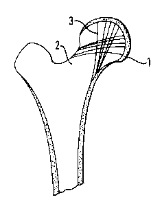
As shown in Figure 1 the natural construction of a femur
consists of an outer hard bone, usually referred to as the cortex,
which in the region of the ends of the femur encases a spongy
interior. The cortex extends over the head of the femur, indicated by
reference numeral 1, but is very thin at the junction of the head 1 and
the neck 2. Trabecular fibres, indicated by reference numeral 3,
sprout from the cortex upwardly and through the head 1, as shown in
Figure I. It has been observed that, if the bone is cut, these fibres
are best able to reform around sharp surfaces.
Figure 2 shows a prosthetic femoral component according to the
present invention and this comprises an insert portion 5 adapted for
location in a prepared socket in the femur in which it is to be fitted
and an enlarged proximal head portion 6, the distal part 8 of which is
also intended to be located in the socket. The distal part 8 of the
head portion 6 is formed as a series of radially projecting steps 7
which act as means to encourage the reformation of the trabecular
fibres in that region. A bore 9 extends through the head portion 6 and
into the insert portion 5.
A bearing element 10 is provided which can be made from metal
or any other suitable material and this comprises a part-spherical
bearing ball 11 which is adapted to extend over the head portion 6.
The bearing ball 11 is hollow and extending from it is an elongate
spigot 12 which is dimensioned and adapted to pass through the bore 9
in the head portion 6 and into the insert portion 5.
The distal portion of the bore 9 in the insert portion 5 is
tapered inwardly as will be seen most clearly at the left hand side of
Figure 3 from the tapering thickness of the side walls. As the spigot
12 is pressed inwardly it causes the side walls of the insert portion 5
to expand outwardly to the position shown at the right hand side of
Figure 2 and from Figure 4.
Inspection of Figure 3 will show the taper extending inwardly
before the ball 11 is pressed completely into position.
CA 02342056 2001-03-26
_g_
The spigot 12 is integral with the hollow ball 11.
Figure 3 shows the prosthetic femoral component in position in
a femur indicated by reference numeral 14. The cortex is indicated by
reference numeral 15 and the spongy interior by reference numeral 16.
In order to apply the prosthetic femoral head the natural head is
resectioned immediately above the neck 17 of the femur and is cut to
provide a bore 18, the proximal end of which is enlarged to provide a
series of radially inwardly extending steps 19. It is important to cut
the bone above the base of the femoral head thereby retaining the
maximum amount of trabecular fibres which are indicated by reference
numeral 20.
The insert portion 5 and the head portion 6 can be made of any
suitable materials, for example a synthetic resin and carbon fibres,
typical examples being PEEK (polyetheretherketone) or PBT
(polybutalieneterephthalate) resin into which a chopped carbon fibre
can be incorporated. Preferably the material is of a similar
compressive modulus as cancellous bone.
When the insert portion 5 is pressed into position it will be
seen that the steps 7 are aligned and co-operate with the steps 19 in
the bone. This encourages growth of the trabecular fibres to reform
around the sharp corners of the steps thus assisting in relaying loads
from the bearing element provided by the ball 11 to the cortex 15.
The bearing element 10, in the form of the part spherical
bearing ball 11, is shown in two different positions in Figure 3. In
the upper position it is part inserted down to the point where its
spigot 12 is about to engage the tapered portion 21 of the bore 9. As
the ball 11 is pushed further into position it causes the outer
circumference of the insert portion 5 to expand outwardly into the soft
core of the bone. In order to assist in providing a grip the insert
portion 5 carries a series of circular indentations 22 (most clearly
seen in Figure 2).
CA 02342056 2001-03-26
-10-
When the ball head 11 is fully in place it closely surrounds
the head portion 6 and can transmit loads through it.
Figure 5 shows an alternative construction in which the
radially projecting steps 7 are replaced by radially projecting fins 77
intended to achieve the same effect.
Figure 4 shows an alternative construction and the same
reference numerals are used to indicate similar parts. In this
arrangement the proximal end 40 of the head portion 41 is substantially
flat and a bearing element is formed by a substantially sold part-
spherical member 42. This is provided with a tapered blind bore 43 to
accept a spigot 44 provided with a suitably tapered boss 45. A morse
taper is provided between the parts so that they lock together when in
position. The member 42 is made from a ceramic material, for example
alumina zirconium or zirconium toughened alumina, and the spigot 44 is
metal. The spigot 44 engages in the insert portion 5 in a similar
manner to that described with regard to Figures 2 and 3.
As mentioned above, the insert portion 5 and the head portion
41 can be made from a synthetic plastics material and this can be
coated with plasma sprayed hydroxyapatite (HA) coating which is
osteo-conductive and stimulates bone growth. Alternatively they could
be made from metal, for example, titanium, with a porous coating such
as a coating as set forth above.
The advantage of the invention is that it involves minimally
invasive surgery.
In all the above constructions the surface finish of parts
which abut bone can be in the form of a cut-away honeycomb.
In the constructions described above the insert portion is
driven into the bone but it could be held by cement. Thus a small
amount of cement could be applied at the proximal end of the insert
portion, bone growth being relied upon towards the distal end.