Note : Les descriptions sont présentées dans la langue officielle dans laquelle elles ont été soumises.
CA 02342385 2001-03-28
ITW CASE 12244
U-NUT FASTENER AND COLLATED STRIP OF U-NUT FASTENERS
FIELD OF THE INVENTION
The present invention relates generally to fasten-
ers, and more particularly to a new and improved U-nut fas-
tener which is adapted to be mounted upon edge portions of
panels, plates, or the like, and wherein each U-nut fasten-
ers is uniquely structured so as to permit a plurality of U-
nut fasteners to be nested, stacked, or collated whereby the
fasteners are able to be used as a strap of fasteners within
the magazine of a tool for serially applying the fasteners
to the edge portion of the mounting plate, panel, or the
like.
BACKGROUND OF THE INVENTION
U-nuts are widely used as fasteners or support
brackets within the automotive and other industries for
mounting various components, such as, for example, modules,
door panels, hinges, and the like, upon support panels,
plates, beams, and the like. U-nut type fasteners conven-
tionally comprise a U-shaped spring clip which has a flex-
CA 02342385 2001-03-28
ibly resilient annular hoop or retainer ring, having a cen-
tral aperture, partially sheared from a first one of the
arms of the U-shaped spring clip, and an internally thread-
ed sleeve or nut member which is integrally formed upon a
second one of the arms of the U-shaped spring clip for
threadedly receiving a threaded bolt or similar type fasten-
er which is also passed through an aperture defined within
the support plate or panel whereby the U-nut and bolt fas-
teners can be fixedly secured upon the support plate or pan-
el so as to in turn secure one of the aforenoted components
upon the support plate or panel. The second one of the arms
of the U-shaped spring clip is also preferably provided with
an upwardly bent forward edge or lip portion so as to facil-
itate insertion of an edge portion of the support panel or
plate between the two arms of the U-nut.
U-nuts are thus mounted upon a support panel or
plate by inserting, in effect, an edge portion of the sup-
port panel or plate into the space defined between the two
arms of the U-nut fastener and subsequently sliding the U-
nut fastener onto the support panel or plate until the flex-
ibly resilient annular hoop or retainer ring engages and be-
comes seated within the aperture defined within the support
panel or plate. The central aperture formed within the first
one of the arms of the U-nut, and serving to define the an-
nular hoop or retainer ring, also permits the passage there-
through of the bolt fastener, and still. further, serves to
somewhat guide the bolt fastener into engagement with the
internally threaded sleeve or nut member formed upon the
second one of the arms of the U-nut. Various types or vari-
ous configurations of U-nut type fasteners are disclosed
2
CA 02342385 2001-03-28
within United States Patent 5,713,707 which issued to Gagnon
on February 3, 1998, United States Patent 5,294,224 which
issued to Kent on March 15, 1994, United States Patent
5,039,264 which issued to Benn on August 13, 1991, United
States Patent 4,798,507 which issued to Olah on January 17,
1989, United States Patent 4,793,753 which issued to Muller
et al. on December 27, 1988, United States Patent 4,729,706
which issued to Peterson et al. on March 8, 1988, United
States Patent 4,684,305 which issued to Dubost on August 4,
1987, and United States Patent 3,426,818 which issued to
Derby on February 1, 1969.
In connection with the sale and distribution of U-
nut fasteners, the same are normally placed in storage bins
in preparation for conveyance to packaging machinery, how-
ever, as can readily be appreciated, due to the unique
structure of U-nut fasteners, the conventional storage of
such fasteners usually results in the :interlocking or en-
tanglement of such fasteners. Such interlocking or entangle-
ment of the fasteners prevents the efficient packaging of
the fasteners, and in addition, inhibits the efficient and
rapid use of such fasteners during installation procedures
because, obviously, the interlocked or entangled fasteners
must first be unlocked or disentangled from each other.
A need therefore exists in the art for a new and
improved U-nut type fastener which permits and facilitates
the stacking or nesting of such fasteners into a collated
strip whereby the fasteners can be packaged in a substan-
tially improved and efficient manner, and for a new and im-
proved collated strip of such fasteners wherein the fasten-
3
CA 02342385 2004-04-27
ers will be readily disposed or oriented for the easy removal
or separation of individual fasteners from the collated or
nested strip of fasteners and for the rapid installation by
operator personnel by means of installation tools specifically
structured for installing such separated U-nut type fasteners
upon support plates, panels, or the like.
SUb~ARY OF T88 INYBNTION
Accordingly, the present invention seeks to provide
a new and improved U-nut type fastener, and to similarly
provide a new and improved collated strip of U-nut type
fasteners.
Further, the present invention seeks to provide a
new and improved U-nut type fastener which effectively
overcomes the various disadvantages and drawbacks of
conventional U-nut type fasteners.
Still further, the present invention seeks to
provide a new and improved U-nut type fastener which permits
the fasteners to be collated or nested into a collated or
nested strip of U-nut fasteners so as to improve the packaging
efficiency of such fasteners.
Further still, the present invention seeks to
provide a new and improved collated or nested strip of U-nut
type fasteners which enables the individual U-nut fasteners to
be readily installed by operator personnel by means of
4
CA 02342385 2004-04-27
installation tools which are uniquely structured for removing
or separating individual U-nuts from the nested or collated
strip and for installing the separated U-nut fastener upon an
edge portion of a support plate or panel.
The invention in one broad aspect provides a U-nut
type fastener capable of being disposed within a vertically
stacked array of U-nut type fasteners, comprising a first
lower arm member, a second upper arm member, and a bite
portion integrally interconnecting the first lower arm member
and the second upper arm member such that the first lower arm
member, the second upper arm member, and the bite portion
together provide the fastener with a U-shaped configuration.
Means is provided upon the U-nut type fastener for enabling a
first U-nut type fastener to be lockingly nested together with
a second U-nut type fastener in a stacked array comprising
first structure defined upon the first lower arm member and
second structure defined upon the second upper arm member for
locked accommodation within the first structure defined upon
the first lower arm member so as to permit a first U-nut type
fastener to be lockingly nested together with a second U-nut
type fastener in a stacked array when the first structure of a
first U-nut type fastener is lockingly engaged with the second
structure of a second U-nut type fastener.
CA 02342385 2004-04-27
Also comprehended by the invention is a
vertically stacked array of U-nut type fasteners,
comprising a first lower U-nut type fastener, and a
second upper U-nut type fastener lockingly nested atop
the first lower U-nut type fastener. Each one of the
fasteners is as defined above.
More particularly, the U-nut type fastener
comprises a U-shaped spring clip which has a flexibly
resilient annular hoop or retainer ring, having a central
aperture, partially sheared from a first one of the arms
of the U-shaped spring clip, and an internally threaded
sleeve or nut member which is integrally formed upon a
second one of the arms of the U-shaped spring clip for
threadedly receiving a threaded bolt or similar type
fastener which is also adapted to be passed through an
aperture defined within the support plate or panel
whereby the U-nut and bolt fasteners can be fixedly
secured upon the support plate or panel so as to in turn
secure one of the aforenoted components upon the support
plate or panel. The internal diameter or diametrical
extent of the central aperture defined within the annular
hoop or retainer ring is substantially the same as the
external diametrical extent of the internally threaded
sleeve or nut member such that, for example, the annular
hoop or retainer ring of a first upper U-nut fastener can
be fitted upon or over the upstanding threaded sleeve or
nut member of a second lower U-nut fastener whereby the
5A
CA 02342385 2004-04-27
fasteners can be nested or stacked in a vertical array. In
addition, a lower one of the U-nut fasteners has an upturned
edge portion integrally formed upon its upper arm for inser-
tion within a recessed portion formed within the lower arm
of an upper one of the U-nut fasteners such that the fasten-
ers within the vertically stacked or nested array cannot ro-
tate with respect to each other such that the orientation of
the fasteners within the nested or stacked array is properly
maintained. Still further, a dimple is provided upon the up-
per surface of the upper arm of each U-nut such that when
the fasteners are stacked or nested, the dimple of a lower
one of the fasteners engages the undersurface of an upper
one of the fasteners so as to maintain the fasteners sub-
stantially parallel and spaced with respect to each other
within the vertical array such that the aforenoted tools can
engage the fasteners and serially separate the lowermost one
of the fasteners from the vertically stacked array when in-
stallation of the same upon the support plate or panel is
desired.
BRIEF DESCRIPTION OF TAE DRAwINaS
Various other aspects, features, and attendant
advantages of the present invention will be more fully
appreciated from the following detailed description when
considered in connection with the accompanying drawings in
which like reference characters designate like or
corresponding parts throughout the several views, and wherein:
6
CA 02342385 2001-03-28
FIGURE 1 is a perspective view of a new and im-
proved U-nut type fastener constructed in accordance with
the principles and teachings of the present invention and
showing the cooperative parts thereof;
, FIGURE 2 is a side elevational view of the new and
improved U-nut type fastener constructed in accordance with
the principles and teachings of the present invention and as
disclosed within FIGURE 1;
FIGURE 3 is a top plan view of the new and improv-
ed U-nut type fastener constructed in accordance with the
principles and teachings of the present invention and as
disclosed within FIGURES 1 and 2 except that the fastener is
illustrated in its form prior to folding the same substan-
tially in half upon itself so as to finalize formation of
the fastener so as to have its U-shaped configuration;
FIGURE 4 is a perspective view of a pair of U-nut
type fasteners, constructed in accordance with the princi-
ples and teachings of the present invention and as disclosed
within FIGURES 1 and 2, wherein the pair of U-nut type fas-
teners are disclosed in a vertically stacked or nested array
which is particularly adaptable for use in a magazine of a
tool for applying individual ones of the U-nut fasteners to
edge portions of a support plate or panel; and
FIGURE 5 is a side elevational view of the verti-
cally stacked or nested array of U-nut type fasteners as
disclosed within FIGURE 4.
7
CA 02342385 2001-03-28
DETAILED DESCRIPTION OF THE PREFERRED EMBODIMENT
Referring now to the drawing, and more particu-
larly to FIGURES 1 and 2 thereof, a new and improved U-nut
type fastener constructed in accordance with the principles
and.teachings of the present invention is disclosed and is
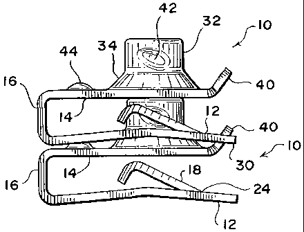
generally indicated by the reference character 10. As is ap-
parent, the U-nut fastener 10 is seen to comprise a first
lower arm member 12, a second upper arm member 14, and an
intermediate folded bite portion 16 integrally interconnect-
ing the first and second arm members 12,14 such that the ov-
erall fastener 10 has a substantially U-shaped configuration
with the first and second lower and upper arms 12,14 dispos-
ed substantially parallel to each other. The fastener 10 can
be fabricated by means of suitable extrusion or stamping op-
erations from a sheet metal blank so as to have an original
unfolded form as seen in FIGURE 3, and it is further seen
that the first lower arm member 12 has integrally formed
therewith an annular hoop member or retainer ring 18 which
is partially severed as at 20 from a main or primary arm
portion 22 of first lower arm member 12 such that the annu-
lar hoop member or retainer ring 18 is flexibly and rote-
grally connected to the main or primary arm portion 22 of
first lower arm member 12 by means of a hinge portion 24.
The annular hoop member or retainer ring 18 has a central
aperture 26 defined therein, and is normally disposed in an
inclined mode at a predetermined angle with respect to the
main or primary arm portion 22 for a purpose to be discussed
more in particular hereinafter in connection with the mount-
ing of the U-nut fastener 10 upon an edge portion of a sup-
port plate or panel, not shown. Lastly, the first lower arm
8
CA 02342385 2001-03-28
member 12 is also provided with a recessed cut-out region 28
which is defined within the free end or forward edge portion
30 thereof for a purpose which will also be discussed more
in particular hereinafter in connection with the stacking or
nesting of a plurality of the U-nut fasteners when forming a
vertical array of the U-nut fasteners for packaging and use
within a suitable installation tool.
The second upper arm member 14 is provided with an
internally threaded, upwardly projecting sleeve or nut mem-
ber 32 which is substantially axially aligned with the aper-
ture 26 defined within the annular hoop member or retainer
ring 18 so as to accommodate a threaded bolt fastener, not
shown, which is adapted to be passed through an aperture de-
fined within the support plate or panel upon which the U-nut
fastener 10 and the component, also not shown, are to be
mounted. A frusto-conical member 34 integrally connects the
lower end portion of the sleeve or nut member 32 to an upper
surface region of a main or primary arm portion 36 of second
upper arm member 14 so as to properly distribute the thread-
ed load onto the support plate or panel, not shown. The sec-
ond upper arm member 14 is also provided at its free end or
forward edge portion 38 with an upwardly inclined latch pro-
jection 40 which is adapted to mate with the recessed cut-
out portion 28 of the first lower arm member 12 when a plu-
rality of U-nut fasteners 10 are nested or collated together
in a vertically stacked array as will be more fully discuss-
ed hereinafter.
With reference now being made to FIGURES 4 and 5,
a pair of U-nut fasteners 10,10 constructed in accordance
9
CA 02342385 2001-03-28
with the principles and teachings of the present :invention
are shown nested or stacked together in a vertical array. It
is to be understood,, howwer, that while FIGURES 4 and 5
disclose a pair of stacked or nested U-nut fasteners 10,10,
such is strictly for illustrative purposes only in order to
disclose the various structural features characteristic of
the U-nut fastener 10 constructed in accordance with the
principles and teachings of the present invention and to ad-
ditionally illustrate how such structural features of the U-
nut fasteners 10 of the present invention enable the U-nut
fasteners 10 of the present invention to be stacked or nest-
ed in a vertical array so as to form a stacked or nested ar-
ray of U-nut fasteners 10 which is formed in accordance with
the principles and teachings of the present invention. More
particularly, in accordance with the principles and teach-
ings of the present invention, the stacked array of U-nut
fasteners 10 preferably comprises more than just two stacked
or nested U-nut fasteners 10,10 and may comprise, for examp-
le, a dozen U-nut fasteners so as to in fact form a stacked
or nested array of U-nut fasteners 10 which may be utilized
as a fastener magazine within a fastener installation tool.
In order to form the stacked array of U-nut fas-
teners as disclosed within FIGURES 4 and 5, it is to be ap-
preciated that the internal diametrical extent of the annu-
lar hoop member or retainer ring 18 is substantially the
same as the external diametrical extent of the upstanding
sleeve or nut member 32. The annular hoop member or retainer
ring 18, however, is somewhat resiliently flexible, and con-
sequently, when a first upper one of the U-nut fasteners 10
is disposed atop a second lower one of the U-nut fasteners
CA 02342385 2001-03-28
so as to form the vertically stacked or nested array of
the U-nut fasteners 10,10, the annular hoop member or re-
tainer ring 18 of the first upper one <-~f the U-nut fasteners
10,10 flexes or expands radially outwardly somewhat so as to
5 accommodate the upstanding sleeve or nut member 32 of the
second lower one of the U-nut fasteners 10,10 whereby the U-
nut fasteners 10,10 are effectively locked together. In ord-
er to in fact ensure or enhance such locking together of the
stacked or nested U-nut fasteners 10,10, it is further seen
10 that each one of the upstanding sleeve or nut member 32 of
each one of the U-nut fasteners 10,10 is provided with a
pair of detents or indentations 42 upon diametrically oppo-
site sides of the upstanding sleeve or nut member 32. It is
noted that each detent or indentation 42 has a substantially
elliptical or oval-shaped configuration and that the major
axis of the elliptical or oval-shaped detent or indentation
42 is inclined with respect to the horizontal whereby such
major axis is disposed at an angular inclination which sub-
stantially matches the inclination of the annular hoop mem-
ber or retainer ring 18. In this manner, the nlanP ~f the
annular hoop member or retainer ring 18 is in effect aligned
with the major axis of the detent or indentation 42 where-
upon the side portions of the annular hoop member or retain-
er ring 18 will be properly seated within or engaged with
the detents or indentations 42.
When the pair of U-nut fasteners 10,10 are dispos-
ed in the illustrated vertically stacked or nested array, it
is further noted that the upwardly inclined latch projection
40 of the lower one of the U-nut fasteners 10,10 is engaged
within the recessed or cut-out edge portion 28 of the upper
11
CA 02342385 2001-03-28
one of the U-nut fasteners 10 while the forwardly projecting
edge portions 30,30 of the upper one o:f the U-nut fasteners
rest upon or engage the forward edge portions :38,33 of
the lower one of the U-nut fasteners 10. This engagement or
5 disposition of such structure serves two purposes. The int-
erengagement of the latch projection 40 of the lower U-nut
fastener 10 with the recessed or cut-out portion 28 of the
upper U-nut fastener 10 prevents relative pivotal or rota-
tional movement of the fasteners 10,10 with respect to each
10 other whereby the fasteners 10,10 will in effect remain in
their vertically aligned stacked array. In addition, the
interengagement of the forward edge portions 30,30 of the
upper one of the U-nut fasteners 10 with the forward edge
portions 38,38 of the lower one of the U-nut fasteners 10
serves to maintain the fasteners 10,10 in a substantially
horizontally parallel mode as can best be appreciated from
FIGURE 5.
As a further and last feature of the new and im-
proved U-nut fastener 10 constructed in accordance with the
teachings and principles of the present invention, and in
conjunction with the aforenoted structure for maintaining
the stacked or nested fasteners 10,10 in a substantially
parallel disposition or orientation, it is also seen that a
dimple 44 is provided upon a rearwardly disposed upper sur-
face portion of the upper arm member 14. Again, as can best
be appreciated from FIGURE 5, the dimple 44 of the lower one
of the fasteners 10 engages an undersurface portion of the
lower arm member 12 of the upper one of the fasteners 10
such that the rear end portions of the stacked or nested U-
nut fasteners 10,10 are maintained in a spaced relationship
12
CA 02342385 2001-03-28
with respect to each other whereby the aforenoted desired
parallel mode or orientation of the fasteners 10,10 is
achieved. It is noted Mill further that such spacing be-
tween such rear portions of the stacked or nested fasteners
10,10 also serves to permit a component of a suitable in-
stallation tool to be inserted within such space so as to in
effect separate, for example, the lowermost one ~f rhP fa~-
teners 10 from the vertical stack or array of fasteners 10
disposed, for example, within a magazine of an installation
tool, not shown, whereby individual fasteners 10 can be ap-
plied to edge portions of a support plate or panel, also not
shown. It is also noted that when a particular fastener 10
is slidably mounted upon an edge portion of the support pan-
el or plate which, as has been noted hereinbefore, is pro-
vided with an aperture for permitting a bolt fastener, not
shown, to be inserted therethrough, the flexibly resilient
annular hoop member or retainer ring 18 will be snap-fitted
into such support plate or panel aperture so as to properly
seat the fastener 10 upon the support plate or panel.
Thus, it may be seen that in accordance with the
teachings and principles of the present invention, a new and
improved U-nut type fastener has been developed wherein the
structure of such fasteners uniquely permits the fasteners
to be arranged within vertically nested or stacked arrays so
as to improve the packaging efficiency of such fasteners,
and in addition, to permit such vertically stacked or nested
arrays of such fasteners to be readily installed within mag-
azines of installation tools whereby the tools can easily
and readily separate such fasteners and install the same
upon edge portions of the support plates or panels. More
13
CA 02342385 2001-03-28
particularly, the annular hoop member or retainer ring of an
upper one of the fasteners is seated upon and annularly sur-
rounds or engages the upstanding sleeve member or threaded
nut of a lower one of the fasteners, the upwardly extending
forward projection of a lower one of the fasteners engages a
recessed forward edge portion of an upper one of the fasten-
ers, and a dimpled portion of a lower one of the fasteners
engages an undersurface portion of an upper one of the fas-
teners. All of such structure serves to maintain the fasten-
ers in the stacked or nested array wherein the fasteners are
disposed, in effect, in a parallel spaced arrangement which
permits the installation tool to separate the lowermost one
of the fasteners from the remaining fasteners and apply such
separated fastener to the edge portion of the support plate
or panel.
Obviously, many variations and modifications of
the present invention are possible in light of the above
teachings. It is therefore to be understood that within the
scope of the appended claims, the present invention may be
practiced otherwise than as specifically described herein.
30
14