Note : Les descriptions sont présentées dans la langue officielle dans laquelle elles ont été soumises.
CA 02343629 2001-04-10
29703.00
FOAM PROTECTIVE UNITS AND EXTENDERS
Claimed Prioritv
This application is a continuation-in-part patent
application of U.S. patent application serial number
09/560,055 filed April 27, 2000 (pending), which relies
on provisional patent application serial number
60/184,917 filed on February 25, 2000.
Field of the Invention
The present invention relates to a novel
adsorbent/absorbent material that is used in association
with packaging systems and/or cleaning pads for
industrial and medical applications.
Background of the Invention
Prior attempt's to control leaking materials have
been disclosed in U.S. Patent No. 4,749,600 (Inventors:
Cullen et al.) Cul.len et al. disclose a packet for
absorbing and immobilizing a liquid. The packet looks
like a sugar packet. (See Figure 3 of the '600 patent) by
having an outer layer and inner contents. When the
packet is to be used, it is inserted within an outer
container, like a Federal Express package. In most
instances, the packet falls to the bottom edge, in
particular a corner, of the outer container. See Col.
2, lines 46 of the '600 patent. Along with the packet,
an inner container of a liquid, like a test-tube of
blood (See Figure '. of the '600 patent) is inserted into
the outer container. According to the '600 patent, the
bottom edge of the inner container should contact the
packet. Thus, when the blood spills from the inner
container, the blood may contact the packet.
CA 02343629 2001-04-10
- 2 - 29703.00
If the blood contacts the packet, the blood
dissolves the outer layer. The packet has an inner
layer of polyvinyl. acetate and an outer layer of starch
paper or any other liquid-degradable material. The
polyvinyl acetate has to be the inner layer in order for
the packet to be formed. See col 2, lines 9-11 of the
'600 patent.
When the outer layer dissolves, the inner contents
are released and form a gel-like substance by absorbing
the blood. The inner content is sodium polyacrylate
having the formula (C3H302Na) I,. It is obtainable under
the trademark WATF;R LOCK J-550 from Grain Processing
Corporation.
A problem with the Cullen et al. attempt to
immobilize a liquid, is that the packet is so small that
it is possible that the liquid may never contact t:he
packet. For example, if the packet is located at the
bottom of the outer container, as Cullen et al. suggest,
and the liquid leaks to the top of the outer container,
the packet will never immobilize the liquid since the
liquid never contacts the packet. Thereby, the liquid
spills from the outer container and provides little
protection to the handler of the package. These results
could be extremely deleterious to the handler. For
example, if the liquid is HIV contaminated and that
liquid contacts a cut on the handler, that handler could
become infected.
A closer reference is U.S. Patent no. 5,984,087,
assigned to Technicor, Inc. - the owner of this
application. In i:he '087 patent, the invention "relates
to a packaging container designed to transport an inner
container containing a liquid. The packaging container
has at least one aealing multi-layer comprising a first
water soluble film and an absorbent material. The inner
CA 02343629 2001-04-10
- 3 - 29703.00
layer of the packaging container is the water-soluble
film that forms the boundary between the cavity that
hold the inner container and the packaging container.
When the liquid leaks from the inner container while in
the packaging container, the liquid dissolves the
water-soluble film. When the film is dissolved, the
absorbent material is released to absorb and immobilize
the liquid material. This immobilization prevents the
liquid from escaping from the packaging container."
'087 Patent, Abstract of the Invention. The present
invention discloses another embodiment of that invention
which was not fully disclosed in the '087 patent.
Summary of the Invention
The present invention relates to a packaging unit
designed to absorb and/or adsorb liquid that is being
transported or was spilled or was released. The
packaging unit has at least one sealing multi-layer
comprising a first water soluble film and an
absorbent/adsorbent material. When the liquid contacts
the water soluble Eilm, the liquid passes through the
water-soluble film. When the liquid contacts the
absorbent/adsorbent material, the absorbent/adsorbent
material immobilizes the liquid material. This
immobilization prevents the liquid from escaping from
the absorbent/adso:rbent material. Moreover, the
invention has a protection layer and/or a transition cap
which allows units to be shipped together.
Brief Description of the Drawings
Figure 1 is a perspective view of a plurality of
packaging containers.
CA 02343629 2001-04-10
- 4 - 29703.00
Figure 2 is a cross-sectional view of Figure 1
taken along the :line 3-3.
Figures 3 to :L8 are alternative embodiments of
Figure 2.
Figure 18a is an exploded view of Figure 18 of
element 150.
Figures 19a and 19b show alternative structures of
the absorbent/adsorbent material 16 and alternative uses
thereof.
Figure 20 is a scale for the present invention.
Figure 21 is a shipping container for Figures 1-17
and other article:> thereof.
Figure 22a and 22b are alternative embodiments of
the present invent:_ion.
Figure 23a and 23b are alternative embodiments of
Figure 16.
Detailed Description of the Present Invention
U.S. Patent no. 5,984,087, which is commonly
assigned, is hereby incorporated by reference.
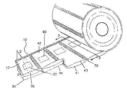
One version of the packaging container 10 for
adsorbing/adsorbing and immobilizing a liquid (not
shown) is shown a1. Figure 1. In this embodiment, the
container 10 is w_Lthin a roll 9 with a plurality of
other containers :LO. Each container 10 includes a
multi-layer film wherein the outer layer 12 is shown.
The outer layer 1:? is any suitable material such as
paper, cardboard, wood, or plastic, but preferably a
water-insoluble material. Examples of some
water-insoluble materials that can be used for the outer
layer 12 include i:hermoplastic resin films, laminated
films prepared from two or more thermoplastic resin
films, and laminat=ed films prepared from a thermoplastic
resin film and paper, metallic foil, woven fabric or
CA 02343629 2001-04-10
- 5 - 29703.00
unwoven fabric. Preferable thermoplastic resins include
polymers and copolymers of olefins, such as ethylene,
propylene, butene, pentene, hexene, and the like;
polymers and copolymers of vinyl compounds such as vinyl
chloride, vinylidene chloride, vinylacetate, vinyl
alcohol, acrylic ester, methacrylic ester,
acrylonitrile, styrene and the like, polymers of
diolefins such as butadiene, isoprene, and the like;
copolymers of the above-mentioned olefins, or vinyl
compounds; polyamides; and polyesters such as
polyethylene terephthalate and the like.
The container 10 has at least two sides - a top
side 42 and a bottom side 44. The bottom side 44 is
either the same length as the top side 42, as shown in
Figure 1, or longer than the top side 42, as shown in
Figures 14 and 15, so the bottom side 44 has a flap 40.
The flap 40 is designed to fold over onto a portion of
the top side 42, as shown in Figure 15 or into the top
side 42. In contrast, when the bottom side 44 is the
same length as the top side 42, the bottom side 44
connects to the top side 42 as shown in Figure 17a.
In any embodiment, the inner layer 41 of the flap
40 contacts the top side 42 by various conventional
methods. One method, which is shown in Figures 2-9,
uses a conventional sealant material 90. Such a sealant
material 90 includes polyvinyl acetate, ethylvinyl
acetate or glue. These sealant materials 90 can be
film-like as shown in Figure 2 or a dot matric coating
as shown in Figure 3. In any case, these sealant
materials 90 adhere to the top side 42 and/or underside
43 of the top side 42 by conventional sealing processes,
such as crimping, adhesive, pressure sealing, or heat
sealing to ensure the package 10 is tamper resistant and
impact resistant.
CA 02343629 2001-04-10
- 6 - 29703.00
Alternatively, the material need not have an
adhesive 90 thereon if the material will be crimped, as
shown in Figures 10-11.
Another method to seal the package container 10,
and make it tamper resistant and impact resistant, is
merely heat sealing or pressure sealing the edges of the
package 10 together with the tab 40 as shown in Figures
14-15, or without a tab 40 as shown in Figures 16-17.
Reverting to Figure l, the packaging container 10
is used to transport liquids or gelatin materials,
hereinafter liquid material (not shown), from one place
to another. The liquid material (not shown) can be a
biological, a radioactive, a pesticide, and/or a
chemical agent.
A vial 30 contains the liquid (not shown). The
vial 30 is any type of container that can securely hold
the liquid material. (not shown) and fit within the
container 10. They vial 30 can be a rigid material. such
as glass, metallic:, ceramic, plastic or the like, or a
flexible material like a conventional flexible plastic
material. The vial 30 should be sealable for
transportation purposes. An example of the seal
includes a cap 36 which holds the liquid (not shown)
sealed within the vial 30. Sometimes, the liquid (not
shown) leaks from the vial 30. When this occurs, the
inner layer of the container 10 controls the leaking.
Turning to Fi.c~ure 2, the container 10 has the outer
layer 12, a cavity 50 to hold the vial 30, an
absorbent/adsorbent material 16, and a first layer of a
water-permeable material 14. The layers 12 and 14 are
superimposed upon each other and seal together at the
peripheral edges 66 of the container 10. At the
peripheral edges E.6, the layers 12, 14 are sealed
together by conventional methods, such as heat sealing,
CA 02343629 2001-04-10
- 7 - 29703.00
pressure sealing, scrimping, and/or adhesive. Between
layers 12, 14 is t'~e absorbent/adsorbent material 16.
The absorbent/adsorbent material 16 is contained within
the two layers 12, 14 until the liquid permeates through
the first layer 14, which can dissolve or allow a .liquid
to penetrate therethrough.
The first layer 14 is any conventional water
permeable material, such as starch paper, polyvinyl
acetate, water-soluble synthetic polymer films, water
soluble semisynthetic polymer films, and water-soluble
natural polymers. Examples of water soluble synthetic
polymer films include partially saponified polyvinyl
alcohol, polyethers, such as polyethylene oxide and the
like, polyvinylpyrrolidone, ethylenically unsaturated
acids, such as acrylic acid, methacrylic acid, malefic
acid, and polymers formed from their salts thereof.
Examples of water soluble semisynthetic polymer
films include cellulose derivatives, such as
carboxymethyl cellulose, hydroxyethyl cellulose,
hydroxypropyl cellulose, and starch derivatives such as
cyclodextrin. As for the water-soluble natural
polymers, those include carrageena, starch, gelatin, and
chitin.
Layer 14 can also be conventional non-woven and/or
woven materials of plastic, natural products, namely,
wool or cotton, or synthetic materials. In this
embodiment, the layer 14 retains the position of the
absorbent/adsorbent material 16 and allows liquid (not
shown) to penetrate through it.
In any case, liquid (not shown) passes through
layer 14 when liquid (not shown) contacts it. The
absorbent/adsorbent material 16 is then released. When
released, the material 16 absorbs and/or adsorbs by
immobilizing large volumes of aqueous solutions
CA 02343629 2001-04-10
- 8 - 29703.00
including dilute alkalis, dilute acids and body fluids.
The material is, in some samples, sodium polyacrylate
having the formula (C3H302Na)~ and variations thereof. It
is obtainable under the trademark WATER LOCK J-550 from
Grain Processing Corporation. Other similar material 16
can used from Gelock, Inc. of Ohio. The material 16 can
also be a desiccant or water absorbing material.
In some instances, it is desirable to add a
conventional nullifying agent 18, such as a biocide or
equivalent thereof, to nullify a specific undesirable
quality of the liquid (not shown). In some instances,
it is desirable to mix the absorbent/adsorbent material
16 and nullifying agent 18 together as shown in Figure
3.
In another embodiment of the present invention, a
second water permeable material 20 is located between
the first layer 1.4 and the outer layer 12. The second
layer 20 is selected from the same group of materials as
the first layer 14. Moreover, the first layer 14
superimposes upon the second layer 20 and the outer
layer 12, wherein each layer 12, 14, 20 seals together
at the peripheral edges 66. As shown in Figure 4, the
absorbent/adsorbent material 16 and nullifying agent 18
are mixed together between the first and second layers
14, 20.
To ensure safe transport of the liquid (not shown),
sometimes it is advisable to separate the two materials
16, 18. In Figure 5, the nullifying agent 18 is between
the first layer 14 and the second layer 16 while the
absorbent/adsorbent material 16 is between the second
layer 16 and the outer layer 12. In contrast, Figure 6
shows the opposite configuration of Figure 5.
In yet another embodiment of the present invention,
Figures 7 and 8 illustrate a variation of Figures 5 and
CA 02343629 2001-04-10
- 9 - 29703.00
6 respectively. Tree only difference between these
figures is that Figures 7 and 8 both illustrate a third
water permeable material 22. The third layer 22 is
selected from the :>ame group of materials as the first
layer 14. Moreover, the first layer 14 superimposes
upon the second layer 20, third layer 22, and outer_
layer 12, wherein e<~ch interior layer 12, 14, 22, 20
seals together at t:he peripheral edges 66.
Another embod_Lment of the present invention is
illustrated in Figure 9. Figure 9 illustrates Figure 4
without the water insoluble layer 12. Obviously, as
indicated by Figure 9, alternative embodiments of the
present invention also include those embodiments shown
in Figures 4-8 without the.water insoluble layer 22.
Likewise, Figures 10 and 11 respectively illustrate
embodiments of Figures 2 and 9 without any sealing
material 90. ThesES embodiments can be sealed, for
example by crimping or heat sealing. Obviously, as
indicated by FigurE~s 10 and 11, alternative embodiments
of the present invE:ntion also include those embodiments
illustrated in Figures 3-8.
Turning to Figure l, packages 10 can be removed
from roll 9 in sets, as shown in Figures 12 and 13, or
individually, as shown in Figure 9, along perforations
70. Thereby, the user can select the desired number of
packages 10 to be l.ransported.
Turning to Figures 13 and 16, vials 30 are inserted
into cavity 50, preferably within an air pocket therein
to provide further protection. The air pocket can be
incorporated within cavity 50 by normal insertion of the
vial into the cavit::y 50, or by a conventional blower
801. The blower pumps air into the cavity 50 to form
the air pocket. The air pocket forms within the cavity
CA 02343629 2001-04-10
- 10 - 29703.00
50 only after the package 10 is sealed as shown in
Figure 17a.
Turning to Figure 1, alternatively, the package 10
and/or vial 30 can have a security feature 80. The
security feature 80 can be a bar code system or
illustrate the fingerprint, handprint, or thumbprint of
the person who supplied the Liquid (not shown) and/or
who obtained the liquid (not shown). Preferably, the
security feature 80 is positioned on the outer layer,
12, 22, or 20 of the package 10, on the vial 30, or
both.
The security feature 80 can also be an
identification feature, which identifies the type of
test to be conducted on the liquid (not shown); and/or
identifies who supplied the liquid (not shown) or where
the liquid (not spawn) came from.
Another alternative to the identification system
can be a color code system. A particular color on the
outer layer 12, 22, 20 of the package 10, the vial., 30,
or both which identifies which test should be conducted
on the liquid (not. shown). The color can cover the
entire outer layer 12, 22, 20, the vial 30, or both or
just a portion thereof.
In case the absorbent/adsorbent material 16 i.s
activated and absc>rbs/adsorbs the liquid (not shown),
the liquid (not spawn) can be extracted from the
absorbent/adsorbent material 16, and the nullifying
agent 18. The extraction can be accomplished by
conventional biolc>gical processes, for example, osmosis,
chemical processes, or mechanical processes, i.e.,
centrifugation. Thereby, the liquid (not shown) can be
analyzed whether the vial 30 is broken or not.
In yet another embodiment of the present invention
shown at Figure 1~~, the package container 10 can be
CA 02343629 2001-04-10
- 11 - 29703.00
divided into having at least two cavities 50, 50a to
hold two vials 30, 30a. The container 10 is divided,
not always equally, along edge 34 and/or perforations
70. Edge 34 is formed in the same manner as the various
layers of container 10 are joined at peripheral edge 66.
The present invention 10 ensures that if for any
reason liquid (not shown) leaks from vial 30, the liquid
(not shown) will permeate, and dissolve in some
instances, at least. a portion of the first layer 14 and
contact the absorbent/adsorbent material 16 and/or
nullifying agent lEl that completely surrounds the vial
30. And once the 1_iquid passes through the first layer
14, the enclosed agent, either 16 and/or 18, will
nullify and/or absorb/adsorb the liquid (not shown).
Thereby, the handler of the packaging container 10 will
know that no liquid (not shown) should accidently leak
from it.
Alternative embodiments of the packaging system 10
are shown in the following embodiments thereof.
In figures 1E. and 18a, a packaging system 10 having
at least one lid 1.60 and a packaging container 150 with
at least one exterior side 151. The packaging container
150 has a first layer of a water permeable material 14
and a first water impermeable material 12. The inner
layer of the packaging container 150 is the first water
permeable material. 14 and the outer layer of the
packaging containE:r is the first water impermeable
material 12. The first water impermeable material 14
and the first water impermeable material 12 are sealed
together at the pE:ripheral edges 170 of the exterior
side 151. A first: absorbent/adsorbent material 16 is
positioned between the first water permeable material 14
and first water impermeable material 12 and
absorbs/adsorbs, depending on the material used therein,
CA 02343629 2001-04-10
- 12 - 29703.00
and immobilizes any liquid material that leaks from a
vial (not shown) that is transported within the
container 10.
The lid secures to the packaging container 150 by
conventional means such as a snap lid as shown in Figure
18, or a screw lid, an indent lid, and an overlay lid
(along with an indent lid).
Between the lid 160 and the packaging container 150
is a second absorbent/adsorbent material 16a (same or
different material than element 16) positioned between a
second water permeable material 14a (same or different
material than element 14) and a second water impermeable
material 12a (same or different material than element
12) that absorbs/adsorbs and immobilizes the liquid
material that leaks from a vial (not shown).
In one embodiment, as illustrated in figure 18, the
second water impermeable material 12a and the second
water impermeable material 14a are sealed together with
the absorbent/adsorbent material 16a contained within,
at the peripheral edges of the at least one lid. In yet
another embodiment, as illustrated in Figure 18, the
second water impermeable material 14a and a third water
impermeable material 14b are sealed together with the
absorbent/adsorbent material 16a contained within. This
embodiment is then placed between the vessel (not shown)
and the lid 160.
Turning to Figure 19a, the absorbent/adsorbent
material 16, 16a, and/or 16b, is planar in relation to
the outer layer 12.
Turning to Figure 19b, the absorbent/adsorbent
material 16, 16a, 16b, can be corrugated or attached to
a material which is corrugated. Obviously, the
embodiments illustrated in Figures 1-16 can have the
absorbent/adsorbent. material 16, 16a, 16b, be corrugated
CA 02343629 2001-04-10
- 13 - 29703.00
in some way or manner, or planar. The shape of the
absorbent/adsorbent. material 16, 16a, 16b depends on the
configuration and amount of absorbent/adsorbent material
16, 16a, 16b needed. For example, the corrugated style
provides greater absorbency/adsorbency due to the
increased surface area to collect the liquid.
Figure 19b illustrates an absorbent/adsorbent pad
180. The difference with this pad 180 is that it has a
sealable multi-layer film having at least a first layer
of a water permeable material 14 and at least one layer
of a water insolubl_E~ material 12. The water insoluble
material 12 and wager permeable material 14 are
superimposed and bonded to each other at the peripheral
edges 66 of each material. The water permeable material
14 allows a liquid to penetrate through the first layer
14 when the pad 180 is applied to a liquid material.
Between each mater~_al 12, 14 is a corrugated
absorbent/adsorbent: material 16 that absorbs/adsorbs and
immobilizes the liquid material.
An alternative embodiment of Figure 19b is Figure
19a. This embodiment illustrates pad 180 having the
same elements as Figure 19b except a mufti-layered
absorbent/adsorbent material 16 and a second
absorbent/adsorbent: material 890 which is commonly used
within the medical :industry, i.e., cotton, is used.
This mufti-layered material 16-890, obviously can be
used in the embodiments illustrated in Figures 1-1'7, and
maximizes the absorbency/adsorbency of the liquid. The
pads 180 illustrated in Figures 19a and 19b can be used
in medical, industrial, or hygienical applications.
Alternatively, the pads 180 and containers 10 may
have identifiers 80, described above, and transponders
108 incorporated in and/or thereon. The transponders
are conventional units used to identify the pad 180 or
CA 02343629 2001-04-10
- 14 - 29703.00
container 10. The transponders 108 can also contain
information about i.ize material 180, 10, i.e., initial
weight, and help locate the material 180, 10 if it is
lost. Such transpc~nders 180 are conventional tools
known to those ski:Lled in the art. Such as those
transponders discl~~sed in U.S. Patent nos. 4,658,818,
5,725,578, and 5,726,630, which are hereby incorporated
by reference herein.
With a transponder 180 and/or identifier 80, the
technician who receives the pad 180 or container 10
would be able to determine the weight of the fluid that
the adsorbent/adsorbent material 16 immobilized. 'rhe
technician would place the material 180, 10 onto a scale
700, in particular a tray 702, as shown in Figure 20.
The scale 700 has a conventional digital unit with a
display output 704. The scale 700 would also have an
input keypad 706 to enter the information set forth in
the identifier 80, and/or a conventional bar code/
transponder reader 708 that would read the bar code from
identifier 80 or transponder 180. With such
information, the scale 700 should tare the material 10,
180. Hence, the amount of liquid contained in the
material 10, 180 would be known.
This information would assist industrial and
medical technicians know how much liquid has spilled
from the industrial container or come from a human
being.
Turning to Figure 21, a shipping container 900 is
shown. The container 900 has a top section 902 hinged
to a bottom section 904. The bottom section 904 has a
plurality of slots 910 that receive container 10, 180 or
any other instrument having a bar code identifier 80
thereon (hereinafter collectively referred to as
"Material 999"). Each slot 910 is staggered from the
CA 02343629 2001-04-10
- 15 - 29703.00
other slot 910 so t:he bar code identifier 80 of ear_h
Material 999 within the slots 910 is visible. The top
section 902 has a corresponding structure to receive the
Material 999. Alternatively, the container 900 can have
storage compartment:, 930 to store documents or other
instruments thereof.
When a technician receives the container 900, the
technician opens the container 900 and can read each bar
code identifier 80 of Material 999 with a conventional
bar code reader (not. shown) without removing the
Material 999 from t:lze container 900.
With this embodiment, the technician will avoid
unnecessary contact with the Material 999. Thereby,
whatever is contained within the Material 999 has a less
chance of being contaminated or damaged by a technician.
Turning to Figures 22a and 22b, the present
invention can have a protective layer 920 within the
absorbent/adsorbent: material 16 as shown in Figure 22a,
or outside the material 16 and within the packaging
system as shown in Figure 22b. The protective layer 920
can be air or liqu:Ld bubble wrap, foam, or any other
conventional air o:r liquid protective device to ensure
the safe transportation of the vial 30. Use of
protective materia:L 920 can be used in every embodiment
illustrated in this application.
In one embodiment, the protective layer 920 or the
outer layer 12, another layer (not shown) within the
packaging system, <and/or the inner layer 41 can also be
a vapor corrosion :inhibiting liner. The vapor corrosion
inhibiting liner protects the packaging and/or the vial
30 from corrosion, eliminating the need for the costly
application and subsequent removal of greases, oils or
other conventional methods of corrosion protection. One
such inhibiting liner is made by Northern Technologies
CA 02343629 2001-04-10
- 16 - 29703.00
International Corporation of Lino Lakes, Minnesota, and
is called the ZERUST~ liner. The Zerust liner emits an
invisible, odorless and non-toxic vapor (apparently
"cleared by the FDA") that diffuses evenly throughout
the interior of the packaging container. The ZERUST~
VCI molecules will cling to metal and other rustable
surfaces and protect them from rust and corrosion.
After removal, the ZERUST~ VCI molecules vaporize
leaving the vial container clean, dry and corrosion
free.
Another embodiment of the present invention is
shown in Figure 23, wherein the embodiment of Figure 18
(930) is interconnected with a second embodiment of
Figure 18 (931) wherein there is a transition cap 161
that allows the first container 930 to mate with the
second container 931. The transition cap 161 is found
on at least one terminal end of each container 930,931.
The one transition cap 161 is a male coupler 161A and
the other transition cap is a corresponding female
coupler 161B. The coupler can be any system that
securely mates with the other coupler. An example of a
system is a screw-type system. Alternatively, the
transition cap 161 can be just one unit so long as first
and second container 930,931 have threaded edges 932
that mate with the transition cap 161C which has a
barrier 933 blocking the contents from escaping from one
container to another.
While preferred embodiments of the present
invention have been. disclosed, it will be appreciated
that it is not limited thereto but may be otherwise
embodied with the scope of the following claims.