Sélection de la langue

Search

Sommaire du brevet 2344366 

Énoncé de désistement de responsabilité concernant l'information provenant de tiers

Une partie des informations de ce site Web a été fournie par des sources externes. Le gouvernement du Canada n'assume aucune responsabilité concernant la précision, l'actualité ou la fiabilité des informations fournies par les sources externes. Les utilisateurs qui désirent employer cette information devraient consulter directement la source des informations. Le contenu fourni par les sources externes n'est pas assujetti aux exigences sur les langues officielles, la protection des renseignements personnels et l'accessibilité.

Disponibilité de l'Abrégé et des Revendications

L'apparition de différences dans le texte et l'image des Revendications et de l'Abrégé dépend du moment auquel le document est publié. Les textes des Revendications et de l'Abrégé sont affichés :

  • lorsque la demande peut être examinée par le public;
  • lorsque le brevet est émis (délivrance).
(12) Demande de brevet: (11) CA 2344366
(54) Titre français: PROCESSUS ET SYSTEME POUR USINER UNE PIECE A L'AIDE DE MACHINES-OUTILS A COMMANDE NUMERIQUE
(54) Titre anglais: PROCESS AND SYSTEM FOR WORKING A WORKPIECE THROUGH NUMERICALLY CONTROLLED MACHINE TOOLS
Statut: Réputée abandonnée et au-delà du délai pour le rétablissement - en attente de la réponse à l’avis de communication rejetée
Données bibliographiques
Abrégés

Abrégé français

L'invention concerne un processus et un système permettant d'usiner une pièce à l'aide de machines-outils à commande numérique. Le processus de cette invention consiste: à lire une représentation électronique d'un objet destiné à être usiné, puis à mémoriser cette représentation; éventuellement à calculer un modèle mathématique interne dudit objet, en fonction des données produites au cours de l'étape de lecture; à utiliser plusieurs paramètres de mouvement d'un outil destiné à usiner l'objet, ces paramètres concernant notamment les sens, les limites spatiales, et les types de mouvements de cet outil; et à déplacer en temps réel une machine-outil, en fonction de la représentation électronique lue ou du modèle calculé, et des paramètres utilisés.


Abrégé anglais


A process and a system are described for working a workpiece through
numerically controlled machine tools. The process comprises the steps of:
reading an electronic representation of an object to be worked and storing it;
possibly computing an internal mathematical model of the object based on data
obtained from the reading step; providing a plurality of movement parameters
of a tool for working the object, these parameters including directions, space
limits and movement typologies; and real-time moving a working tool based on
the electronic representation being read or the computed model and on the
provided parameters.

Revendications

Note : Les revendications sont présentées dans la langue officielle dans laquelle elles ont été soumises.


CLAIMS
1. Process for working a workpiece through
numerically controlled machine tools,
comprising the following steps:
- reading an electronic representation of an
object to be worked and storing said electronic
representation; and
- real-time moving a working tool of said
numerically controlled machine tool based on
said electronic representation that was read;
characterised in that it further comprises, before
said step of real-time moving a working tool, the
step of:
- providing in real-time, through a user, a
plurality of movement parameters of a tool for
working said object, said parameters including,
together or as an alternative, directions, space
limits and tool movement typologies;
- said step of real-time moving a working tool of
said numerically controlled machine tool being
based also on said real-time provided
parameters.
2. Process according to Claim l, characterised in
that it further comprises, after said step of
reading an electronic representation of an
-1-

object to be worked, the step of:
- computing an internal mathematical model of said
object based on data obtained from said reading
step.
3. Process according to Claim 1 or 2,
characterised in that said real-time moving
occurs by means of commands inserted by an end
user and automatically executed by said
machine tool based on the stored electronic
representation of the object.
4. Process according to Claim 3, characterised in
that said moving step is null if the end user
does not input any command.
5. Process according to Claim 3, characterised in
that said moving step is performed by real-
time computing tool movement coordinates based
on the stored electronic representation of the
object.
6. Process according to any one of the previous
Claims, characterised in that said moving step
allows complying with the workpiece surface
whose representation is known by the system.
7. Process according to any one of Claims 3 to 6,
characterised in that the end user is the
workshop operator responsible for workings on~
-2-

numerically controlled machine tools.
8. System (2, 3) for working a workpiece through
numerically controlled machine tools (1),
comprising:
- means (2) for reading an electronic
representation of an object to be worked and for
storing said electronic representation; and
- means (2) for real-time moving a working tool of
said numerically controlled machine tool (1)
based on said electronic representation that was
read;
characterised in that it further comprises:
- means (2, 3) for providing in real-time, through
a user, a plurality of movement parameters of a
tool for working said object, said parameters
including, together or as an alternative,
directions, space limits and tool movement
typologies;
- wherein said means (2) for real-time moving a
working tool of said numerically controlled
machine tool (1) operate basing also on said
parameters provided in real-time by said means
for providing.
9. System (2, 3) according to Claim 8,
characterised in that it further comprises:~
-3-

- means (2) for computing an internal mathematical
model of said object based on data obtained from
said reading means (2).
10. System (2, 3) according to Claim 8 or 9,
characterised in that said means (2) for real-
time moving operate through commands inserted
by an end user and automatically executed by
said machine tool (1) based on the stored
electronic representation of the object.
11. System (2, 3) according to Claim 10,
characterised in that said means (2) for
moving do not operate if the end user does not
input any command.
12. System (2, 3) according to Claim 10 or 11,
characterized in that said commands are input
through a push-button panel aboard the
machine.
13. System (2, 3) according to Claim 10 or 11,
characterized in that said commands are input
through a keyboard (7) and a display (5) being
present on a control unit (2) of the machine
tool (1) or on a work-station (3).
14. System (2, 3) according to Claim 10,
characterised in that said means (2) for
moving operate by real-time computing tool
-4-

movement coordinates based on the stored
electronic representation of the object.
15. System (2, 3) according to any one of Claims 8
to 14, characterised in that said means (2)
for moving allow complying with the workpiece
surface whose representation is known by the
system (2, 3).
16. System (2, 3) according to any one of Claims
to 15, characterised in that the end user
is the workshop operator responsible for
workings on numerically controlled machine
tools (1).
-5-

Description

Note : Les descriptions sont présentées dans la langue officielle dans laquelle elles ont été soumises.

CA 02344366 2001-03-15
WO 00/19285
PCT/IT99/00277
PROCESS AND SYSTEM FOR WORKING A WORKPIECE THROUGH
NUMERICAI,I,Y CONTROLLED MACHINE TOOLS
The present invention refers in general to a
process and a system for working a workpiece
through numerically controlled machine tools, and
in particular to a process and a system for working
a workpiece through computer-aided copying
techniques.
So far, when it it necessary to realize a copy
of a workpiece through machine tools, three
different types of techniques have been known and
have been applied in the field, obviously starting
from the project design of the piece to be copied,
and apart from the common realization of drawings
on paper, from which production dies are obtained,
etc.
These three techniques are:
a) realizing drawings of the "electronic" type,
that is through Computer Aided Design (CAD)
techniques, these drawings being used for
generating, through Computer Aided
-1-

WD ~0/1(~2~5 CA 02344366 2001-03-15
PCT/IT99/00277
Manufacturing (CAM) techniques, a number of
tool paths that the numeric control of the
machine tool executes in a known way; ,~
b) realizing a physical model of the workpiece to
be copied, to such model a scanning
("digitizing") technique being applied, such
technique allowing to automatically create
paths for the numeric control of the machine
tool similarly to the above technique a); and
c) realizing a physical model of the workpiece to
be copied, to which model the so-called direct
copying technique is applied. Based on this
technique, the outline of the "model" workpiece
is followed by a feeler pin, directly connected
to the copying machine tools that works on the
rough workpiece. The electronic control of the
machine copier is such as to have algorithms
that keep the feeler pin in contact with the
model and make the tool move on the same path
realized by the feeler pin.
The above procedures (b) and (c) are
complicated and costly, since they provide the
presence of a model to be copied and of a machine
tool provided with a feeler pin; moreover, they are
subjected to inaccuracies, since possible model
-2-

CA 02344366 2001-03-15 ~
31-pg-2000
PCT/IT99/00277
wo oon nss 31. 0 8. 2000
PCTIIT99/00277
66
faults are taken to the final copied workpiece.
Procedure (a), instead, is not subjected to faults,
but has complicated aspects and high costs that are
necessary to apply the CAM techniques.
-~y Ns ~T Phi 3A~
Object of the present invention is solving the
above prior-art problems, by providing a process
and a system that allow perfectly reproducing
workpieces to be worked in an automated way,
instant by instant, and simultaneously provide the
workshop operator with the possibility of choosing
movement directions of working tools according to
the best available alternatives, keeping the
perfect correspondence between "virtual" workpiece
to be realized and "real" finished workpiece.
Through the process and system of the present
invention, it is possible to do without the
presence of a model workpiece and of the feeler
pin, and to do without all possible sources of
errors and inaccuracies, since the model of the
workpiece to be copied is stored in the control
memory and is not subjected to variations.
Moreover, it is possible in this way to do without
any technique of the CAM type, with its related
costs, thereby obtaining a result that is at least
equivalent, but often also superior, as regards
-3-
AMENDED SHEET

a71 -0$-2000 CA 02344366 2001-03-15
PCT/IT99/00277
WO-A-93709482, that is considered the closest prior
art, discloses a real time tool working system, in
particular a grinding system, in which, in order to
obtain a copy of an object to be worked, it is
necessary to input into the system the nominal
geometrical characteristics of the blank workpiece
to be worked.
EP-A-0284674 discloses a general CAM method and
apparatus without "virtual copy" functions.
DE-A-4341367 discloses a forming system to prepare
medical protheses for patients that are subjected
to scanning by scanning means.
WO-A-99/61963 deals with a process and apparatus
for creating sequences for NC machine tools that
has a publication date of 02.12.99 and has been
filed on 07.05.99 claiming a priority of 22.05.98.
- 3A -
AMENDED SHEET
,_ ..

CA 02344366 2001-03-15
31-08-2000
PCT/IT99/00277
WO OOI19285 PCTIIT99I002??
yield and accuracy, with respect to CAM techniques
themselves.
The above and other objects and advantages of
the invention, as will appear from the following
description, are obtained by a process and a system
a,nd B
as claimed in Claims 1
respectively. Preferred embodiments and non-trivial
variations of the present invention are claimed in
the dependent Claims.
The present invention will be better described
by some preferred embodiments thereof, given as a
non-limiting example, with reference to the
enclosed drawings, in which:
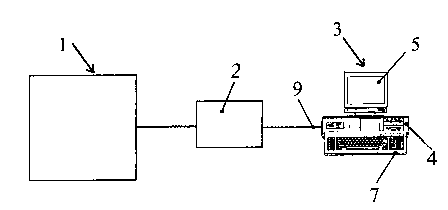
- Figure I is a schematic block diagram of a
first preferred embodiment of a
configuration that allows putting the
present invention into practice; and
- Figure 2 is a schematic block diagram of a
second preferred embodiment of a
configuration that allows putting the
present invention into practice.
With reference to Fig. 1, a first and more
common_embodiment of a configuration for putting
the invention into practice comprises, as is known
in the art, a machine tool 1, for example a milling
-4-
AMENDED SHEET
_..._ _~_~wu,......~~.~_ _~ ... ..

CA 02344366 2001-03-15 '
WO 00/19285
PCT/IT99/00277
machine, to which a control unit 2 is connected,
that can also be a common computerized numerically
controlled unit. The system for realizing the
process of the present invention is placed in the
control unit 2, that, together with the machine
tool l, thereby composes a copying machine tool
real and proper; or, the above system can be
inserted, as said, into an existing computerized
numerically controlled unit 2 (that can be composed
also by a Central Processing Unit (CPU) with
display and keyboard), that therefore performs,
among the others, both functions of working and
copying for the connected machine tool 1.
With reference to Fig. 2, instead, a second
preferred embodiment is shown of the configuration
that puts the present invention into practice, in
which there are always the numerically controlled
machine tool 1 and the control unit 2, with the
addition of a work-station 3, that can be commonly
composed of a Central Processing Unit (CPU) 4, a
display 5 and a keyboard 7. The work-station 3 is
connected through lines 9 or equivalent means to
the control unit 2.
The control unit 2 and/or the CPU 4 contain
therein the software adapted to realize the process
-5-

CA 02344366 2001-03-15
WO 00/19285
PCT/IT99/00277
of the present invention, through adequate means
that can be composed of modules written in any
programming language suitable for such purpose. ~ '
In the following description, the term
~~electronic representation" means the
mathematical/numerical model of an object realized
through known CAD techniques, and these terms are
therefore to be considered as equivalent.
According to the present invention, the system
that allows realizing the process of the present
invention for working a workpiece through computer-
aided numerically controlled machine tools, first
comprises means for reading an electronic
representation of an object to be worked. These
means produce a representation that is commonly in
the form of data files having one of the formats
for describing mathematical surfaces, such as IGES
(Initial Graphics Exchange Specification) or VDA-FS
(Verband der Automobilindustrie Flaechen
Schnittstelle).
The system further comprises means for providing
a plurality of movement parameters of a, tool for
working the object; these parameters are provided
by the user and include, together or as an
alternative, movement directions, movement space
-6-

CA 02344366 2001-03-15
WO 00/19285
PCT/IT99/00277
limits and tool movement typologies.
Finally, the system of the present invention
comprises means for real-time moving the working
tool by means of the numerically controlled machine
tool based on the stored electronic representation
for the object to be worked and on the parameters
chosen by the operator.
According to an alternative embodiment, the
system of the invention can also comprise means for
computing the internal mathematical model of the
object based on data obtained from the means for
reading the representation itself, when such
operation becomes necessary. The means for
computing the internal mathematical model comprise
algorithms of a general and known type, suitable to
provide an approximation of mathematical surfaces
with adequate representations.
As regards the means for real-time moving, they
operate through commands inserted by the end user
and automatically executed by the machine tool
based on the electronic representation of the
object stored therein and on the parameters
previously provided by the operator. The means for
inputting and moving the axes, more widely adopted
by the end user, are a common push-button panel
,.

CA 02344366 2001-03-15
WO 00/19285
PCT/IT99/00277
(not shown) installed aboard the machine, and/or
the keyboard and the display of the control unit 2
and/or of the work-station 3. In this way, the end
user (that in particular is the workshop operator ;
responsible for workings on numerically controlled
machine tools) is enabled to choose the direction
and the type of working that are most appropriate
for the particular current working conditions. In
fact, the operator is left with the most complete
freedom of choice about when and how moving the
machine to realize the workpiece: the means for
moving do not operate at all if the end user does
not insert any command therefor.
A major feature of the present invention is that
the means for moving operate through the real-time
computation of movement coordinates of the tool
based on the mathematical model of the object
stored in'the control unit 2 of the machine tool.
The program for realizing the working tool
movement is commonly implemented by applying known
algorithms for checking the collision between
workpiece and tool.
According to the inventive process, the commands
input by the end user, through a push-button panel
and/or a keyboard, point out a tool movement
-g_
,y... .

CA 02344366 2001-03-15
WO 00/19285
PC'T/IT99/00277
direction and are applied following the
mathematical model and the stored parameters. Based
on the workpiece representation defined in memory,
the system is therefore able to comply with the
parameters defined by the user following the
optimum path stored and realizing it in real time
through the machine tool.
Moreover, in the inventive process, the movement
allows complying (without added inaccuracies in,
addition, obviously, to those intrinsic for the
machine) with the workpiece surface whose
description is known by the system.
Due to this simple and straightforward
configuration, the system of the present invention
allows doing without tool paths that previously had
to be computed through CAM techniques, and also
without the physical model of the workpiece to be
copied.
The mathematical model realized through CAD
techniques or computed for such purpose is stored
in the system .and used as "imaginary surface" on
which the tool moves and behaves as copier
simultaneously following the commands input by the
operator.
-g_
. ..~ .. . . ... ....~.. _~.~.. ._ _ _ .

Dessin représentatif
Une figure unique qui représente un dessin illustrant l'invention.
États administratifs

2024-08-01 : Dans le cadre de la transition vers les Brevets de nouvelle génération (BNG), la base de données sur les brevets canadiens (BDBC) contient désormais un Historique d'événement plus détaillé, qui reproduit le Journal des événements de notre nouvelle solution interne.

Veuillez noter que les événements débutant par « Inactive : » se réfèrent à des événements qui ne sont plus utilisés dans notre nouvelle solution interne.

Pour une meilleure compréhension de l'état de la demande ou brevet qui figure sur cette page, la rubrique Mise en garde , et les descriptions de Brevet , Historique d'événement , Taxes périodiques et Historique des paiements devraient être consultées.

Historique d'événement

Description Date
Exigences relatives à la révocation de la nomination d'un agent - jugée conforme 2021-04-01
Demande non rétablie avant l'échéance 2005-09-01
Le délai pour l'annulation est expiré 2005-09-01
Réputée abandonnée - omission de répondre à un avis sur les taxes pour le maintien en état 2004-09-01
Inactive : Abandon.-RE+surtaxe impayées-Corr envoyée 2004-09-01
Inactive : Page couverture publiée 2001-06-07
Inactive : CIB en 1re position 2001-06-03
Lettre envoyée 2001-05-25
Inactive : Notice - Entrée phase nat. - Pas de RE 2001-05-25
Demande reçue - PCT 2001-05-17
Demande publiée (accessible au public) 2000-04-06

Historique d'abandonnement

Date d'abandonnement Raison Date de rétablissement
2004-09-01

Taxes périodiques

Le dernier paiement a été reçu le 2003-08-29

Avis : Si le paiement en totalité n'a pas été reçu au plus tard à la date indiquée, une taxe supplémentaire peut être imposée, soit une des taxes suivantes :

  • taxe de rétablissement ;
  • taxe pour paiement en souffrance ; ou
  • taxe additionnelle pour le renversement d'une péremption réputée.

Veuillez vous référer à la page web des taxes sur les brevets de l'OPIC pour voir tous les montants actuels des taxes.

Historique des taxes

Type de taxes Anniversaire Échéance Date payée
Taxe nationale de base - générale 2001-03-15
Enregistrement d'un document 2001-03-15
TM (demande, 2e anniv.) - générale 02 2001-09-04 2001-08-27
TM (demande, 3e anniv.) - générale 03 2002-09-03 2002-08-28
TM (demande, 4e anniv.) - générale 04 2003-09-02 2003-08-29
Titulaires au dossier

Les titulaires actuels et antérieures au dossier sont affichés en ordre alphabétique.

Titulaires actuels au dossier
FIDIA S.P.A.
Titulaires antérieures au dossier
GIUSEPPE MORFINO
Les propriétaires antérieurs qui ne figurent pas dans la liste des « Propriétaires au dossier » apparaîtront dans d'autres documents au dossier.
Documents

Pour visionner les fichiers sélectionnés, entrer le code reCAPTCHA :


Pour visualiser une image, cliquer sur un lien dans la colonne description du document. Pour télécharger l'image (les images), cliquer l'une ou plusieurs cases à cocher dans la première colonne et ensuite cliquer sur le bouton "Télécharger sélection en format PDF (archive Zip)" ou le bouton "Télécharger sélection (en un fichier PDF fusionné)".

Liste des documents de brevet publiés et non publiés sur la BDBC .

Si vous avez des difficultés à accéder au contenu, veuillez communiquer avec le Centre de services à la clientèle au 1-866-997-1936, ou envoyer un courriel au Centre de service à la clientèle de l'OPIC.


Description du
Document 
Date
(aaaa-mm-jj) 
Nombre de pages   Taille de l'image (Ko) 
Dessin représentatif 2001-06-07 1 4
Page couverture 2001-06-07 1 32
Description 2001-03-15 10 315
Abrégé 2001-03-15 1 51
Revendications 2001-03-15 5 135
Dessins 2001-03-15 1 11
Rappel de taxe de maintien due 2001-05-24 1 111
Avis d'entree dans la phase nationale 2001-05-25 1 193
Courtoisie - Certificat d'enregistrement (document(s) connexe(s)) 2001-05-25 1 113
Rappel - requête d'examen 2004-05-04 1 116
Courtoisie - Lettre d'abandon (requête d'examen) 2004-11-10 1 167
Courtoisie - Lettre d'abandon (taxe de maintien en état) 2004-10-27 1 176
PCT 2001-03-15 21 668
Taxes 2003-08-29 1 36
Taxes 2001-08-27 1 31
Taxes 2002-08-28 1 31