Note : Les descriptions sont présentées dans la langue officielle dans laquelle elles ont été soumises.
CA 02345942 2001-05-04
SPECIFICATIONS
FIELD OF THE INVENTION
s Control of the direct current electric motor driving the radiator-mounted,
axial flow fan
used in a vehicle's cooling system. The present invention adds a reverse
direction of rotation
of the fan and a fan speed control, for the purpose of blowing air forwards
and outwards from
the front of the vehicle under certain conditions. This provides unexpected
benefits which
include: improved driver safety, faster engine warm-up, and improved cooling
at low or no
1 o speed. direct current motors (brush type) can be run in reverse by
switching polarity of the
power supply (usually 12 volt battery).
BACKGROUND OF THE INVENTION
1 s Cold engine operation has numerous disadvantages. Due the rich fuel
mixture which must
be burnt, fuel consumption is higher, exhaust is dirtier and contains larger
amounts of
unwanted pollutants, and, the excess fuel dilutes the oil film lubricating the
piston-cylinder
surfaces causing excessive wear as well as contaminating the oil. Further,
engine-heated water
is required to defrost/defog the windshield for best visibility for safe
driving. All the above
2o disadvantages are minimized at the preferred engine operating temperature
range of about 200-
210° Fahrenheit (94 -98°C). Consequently, this temperature
should be attained as quickly as
possible from cold (cold can be below -40°F, °C).
Once the engine has reached operating temperature it thereafter produces large
amounts of
unwanted waste heat that must be dissipated to prevent overheating. This heat
is dissipated
zs both by the radiator and by the surface of the engine into the ram air flow
that enters the front
grill as the vehicle is driven. At idle or in slow moving conditions there is
no ram air flow so
the fan switches on and off to create air flow at intervals when needed
according to engine
temperature sensor signal. However the engine surface now receives hot
radiator air and so
cannot be cooled as effectively as when driving at speed. Further that hot air
unwantedly
3o heats the engine bay components and is then discharged beneath the
vehicle's front portion
wherefrom a portion of the hot air finds its way back to the front intake.
Moreover, during
the fan's off interval, the engine bay or underhood compartment: receives no
cooling air and so
the components therein soak up heat and must therefore operate at quite high
temperatures.
These underhood temperatures can reach critical values in long traffic on hot
days.
3s Breakdown of the plastics and electronics in the engine compartment becomes
a serious
concern. Furthermore the passenger cabin has a forward portion or wall
(firewall) which
receives this unwanted heat in hot weather. This adds to interior heat which
the air
conditioner must work harder at to cool down. These anomalies add to the
cooling load of the
radiator which must therefore be larger, heavier and more expensive. Moreover,
the engine bay
ao and its contents, including electronic, electric, computer and numerous
plastic components all
get very hot reaching temperature well over the boiling point of water
(220°F, 105°C) and so
must be made of select, expensive materials to withstand the high
temperatures.
Future vehicle development plans include attaching more related components
directly on
the engine to allow complete package testing. This is expected to further
raise underhood
1
CA 02345942 2001-05-04
component temperature and therefore their cost.
SUMMARY OF THE INVENTION
s The present invention is an improvement to vehicles having a water cooled,
front-
mounted engine with front mounted engine coolant radiator. Such vehicles
commonly have an
axial flow fan mounted parallel to, planar with, and attached to said
radiator. Sometimes dual,
side-by-side fans are used to reduce height requirements. Control of such fans
is the subject of
the present invention.
to Faster warm-up is achieved with the present invention by operating the
axial fan in
reverse to blow air forwards to thereby block cold air from blasting onto the
warming engine
as and until it heats to operating temperature. The speed of the fan may
preferably be varied
according to the speed at which the vehicle is being driven. When the vehicle
stops the fan
stops blowing forwards. When the vehicle speeds up so does the fan, always
blowing at a rate
1 s proportional to (or a function of) the vehicle's road speed. When
operating temperature is
attained, fan operation ceases.
Improving overall cooling is achieved with the present invention by operating
the fan in
reverse to blow air forwards (preferably at full speed) when a vehicle is at
idle and/or is driven
in slow traffic. This draws cooler air from beneath the vehicle cooling the
engine surface,
2o engine bay and all components therein, and the firewall of the cab.
All these benefits are achieved at a lower net vehicle cost (lower cost
underhood
components and materials from lower underhood temperatures, smaller radiator)
and without
adding new structures.
Motor control circuits for automotive fan motors are well known. It is also
well known
2s that the typical brush DC (direct current) may be reversed simply by
switching its electrical
connection, and, that axial fans work in both directions although fan blade
designs are
generally optimized for one direction. The present invention therefore applies
to existing
vehicles refitted to blow forwards. Such fan blades may be designed to operate
equally in both
directions.
3o In the present invention, determination of mode of operation of the cooling
fan (to blow
forward or reverse (motor rotating clockwise or counterclockwise), and the
speed of such
rotation, are made by an electronic motor control circuit of a design well
known in the art
(such as Hexfet Applications, Motor Drives, p.43 from International Rectifier
of El Segundo
California). Inputs from appropriate sensors (also well known in the art)
provide the control
3s circuit engine with temperature data and vehicle road speed data.
The present invention speeds warm-up as follows: at below operating
temperatures, a
temperature sensor signal (where the signal voltage is a function of engine
operating
temperature) 'tells' the control circuit to select reverse mode fan operation.
If and when the
vehicle begins moving, a speed sensor 'tells' the control circuit the vehicle
speed which the
4o control circuit uses to start the fan turning and to continually adjust the
fan's speed to be
proportional to the vehicle's road speed (up to maximum fan speed). Thus the
fan blows air
forwards with the proper force to 'just block' cold air coming in through the
inlet. If the
vehicle speeds up, so does the fan. If the vehicle slows and/or stops, so does
the fan. By this
means the fan constantly 'just blocks' the ingress of unwanted cooling air,
speeding engine
2
CA 02345942 2001-05-04
warm-up.
The fan may also be made to blow forwards at low vehicle speed or while the
vehicle is
idling to bring at least some exhaust-heated air forward through the engine
bay to further
speed engine warm-up.
s The present invention improves cooling as follows. If a vehicle is operated
below a
predetermined road speed (slow moving traffic) and the engine gets too hot,
then, a speed
sensor (for example, a conventional variable reluctance sensor located in the
transmission)
'tells' control circuit to select reverse mode causing fan to blow forward,
cooling radiator and
engine bay. The fan may operate at full speed during this operational
condition. If vehicle
Io continues to operate too hot but road speed increases above a pre
determined maximum speed
range of, say, 20-25 mph (32-40 kph), the the speed sensor 'tells' control
circuit to switch to
normal mode (blowing rearwards) to augment ram air flow. A short time delay
may be
incorporated in the motor control circuit to allow the fan to momentarily stop
before changing
directions.The upper exact speed range limit would partly depend on the speed
of the fan's
1 s air flow. The shape and length of the front grilled opening and the fan
location are other
determinants of the maximum speed range above which the fan is 'told' to
change to blowing
normally or rearwards to assist ram air flow.
Vehicles in stop-and-go traffic exhaust their hot, noxious fumes rearwards
towards
vehicles behind. With the existing cooling fan arrangement, these fumes are
drawn into the
2o engine bay and vehicle interior, especially when heater and/or air
conditioner fans are
operating inside the vehicle, or windows are open. Thus vehicle occupants
unwittingly inhale
toxic fumes.
The present invention solves this serious situation by having the fan blow its
cooling air,
and any noxious fumes, forwards away from vehicle and occupants.
2s Underhood objects such as plastic and electrical components can reach
critically high
temperatures. Plastics, rubbers, paint, hoses, electronics, fluids and other
components may
overheat, dry out, warp, or age quickly, requiring more expensive materials to
resist the
increasingly high temperatures. With the existing cooling fan arrangement, hot
radiator air is
blown into the hot engine bay adding to underhood temperatures.
3o With the present invention hot and noxious underhood air and, hot radiator
air, are blown
out the front inlet of the vehicle while fresher, cooler air is drawn into the
engine bay from
below and beside.
Another use of the present forward blowing fan at zero or slow road speeds, is
to provide
a continual cooling of the engine bay from the radiant and convective heat
given of by the
3s engine's surface. In this application, the fan may run at a low speed until
high engine
temperatures trigger full speed fan operation.
To control the speed of rotation of the fan in warm-up mode, a vehicle speed-
based signal
to the control circuit from a sensor is needed. Such a signal may be generated
by any of
numerous types of sensors or transducers. They include an electrical signal
generated by an
4o existing speedometer transducer; air flow measurement devices such as pitot
tubes and
anemometers; a flap on a shaft that is rotated by ram air flow, the rotation
of which is
detected by a potentiometer or Hall-effect sensor; microphone tuned to sound
generated by
air flow including over resonant tube or reed; air pressure sensors; antenna
deflection; and
power sensing of fan motor as it is impinged upon by ram air which it is
forcing against. Even
3
CA 02345942 2001-05-04
the sensor used in antilock brake systems to detect wheel rotation may provide
a suitable
signal.
Speed control of the fan in reverse mode is important during warm-up because
rotating
too fast would draw excessive cold ambient air over the engine from openings
below and
s about the engine bay. Rotating too slow in reverse mode would allow cold ram
air to enter
with the same result. As the car's speed varies from zero to full speed, the
fan must adjust
it's speed accordingly to maintain a null air flow over the warming engine.
Some benefit can be
had with a simpler system of merely operating the fan at full reverse speed
while warming up,
especially if the vehicle will reach substantial speeds soon after startup.
This will provide
1 o some worthwhile air blocking at minimal cost, i.e., no speed sensor or
control circuit.
Air flow speed sensors may be placed in preferred locations on, in, or about
the vehicle
including obvious locations in the front of the fan, and, in selected area
such as at the lower
edge of the windshield where air flow from the engine may be more stable, or
at vents affected
by external air flow such as in a tail light, or behind the rear window, or
from and antenna
1 s mounted device. Sensors may also include thermistors, resistors whose
resistive value changes
predictably with temperature.
Thermistors may be powered so that they generate heat. Such thermistors are
therefore
cooled by an air flow over them. This cooling at any given temperature is
dependent on air
flow speed, and so the change in resistance produced by the cooling is
proportional to the air
2o speed over the thermistor. This, in turn, provides the needed signal source
for the fan speed
control circuit. In one embodiment of the present invention, two such powered
thermistors
are placed back-to-back in the inlet air stream. That is, one faces forwards
to the inlet
opening, the second faces rearward to the cooling fan. If both thermistors
cool equally then
inlet air flow is stagnant (vehicle stopped or fan counteracting inlet air
flow) and both are
2s losing heat evenly. If air flow from the inlet exceeds that from the
forward blowing fan, then
the first front-facing thermistor will be in direct contact with a faster
moving air stream and so
will cool faster than the rear-facing thermistor which will be in an
aerodynamic air shadow,
and so cool more slowly. This differential resistive condition provides the
signal to the fan
speed control circuit to speed up the fan. If air flow from the reverse-
blowing fan exceeds that
3o from the inlet, then the second rear-facing thermistor will be in direct
contact with a moving
air stream and so, will cool faster than the the front-facing thermistor which
will be in an
aerodynamic air shadow and so, cool slower. This differential condition
likewise provides the
signal to the fan speed control circuit to slow down the fan.
Pressure sensors may include means to detect when intake pressure is at its
highest
3 s indicating blocked air flow, the desired goal, and where a pressure
transducer, or a differential
pressure transducer, supplies the signal to the fan speed control circuit.
Axial motor fan blades are produced in two forms: 'push' or 'pull' the choice
depending
on whether the fan is mounted in front of the radiator (push) or behind the
radiator (pull). To
ensure adequate engine cooling and air blocking capability with the present
invention, the
ao fan's blade design should be selected to maximize air flow dynamics in the
reverse or forward
blowing direction although a neutral design would also be acceptable. Ram air
flow from
vehicle speed augments the air flow of a fan blowing rearwards (normal mode),
it is therefore a
less demanding air moving condition and so the 'wrong' blade design can work.
This means
that retrofitting existing vehicles with the present invention may be
accomplished with only a
4
CA 02345942 2001-05-04
low-cost control circuit and speed sensor. A bi-directional neutral fan blade
design may also
be used.
BRIEF DESCRIPTION OF THE DRAWINGS
s
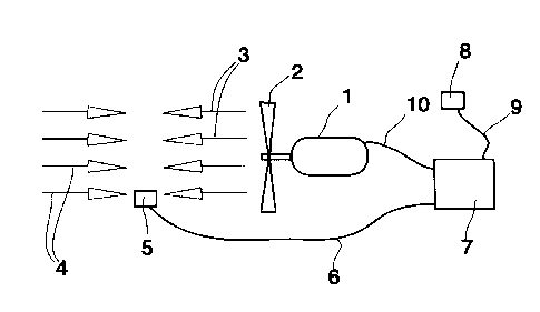
Figure 1 Shows the fan in reverse mode producing a air flow sufficient to
prevent air entrance
through vehicle's grill and the control circuit to adjust speed and to
determine reverse
operation mode from sensors.
Figure 2 A top view of a vehicle at a first road speed showing the long arrows
of vehicle air
to speed and the canceling counter flow of equal value provided by the cooling
fan
operating in reverse mode.
Figure 3 Same as figure 2 where both grill inlet air speed and fan air speed
are substantially
equal and lower than in Fig 2.
Figure 4 shows a mechanical flap air speed sensor.
I s Figure 5 shows a thermistor-based air speed sensor.
Figure 6 shows a speedometer-based speed control circuit with second sensor
detecting speed
of rotation of a wheel or gear.
Figure 7 shows the fan at full speed in reverse mode effect during engine
overheating at low
speed or idling at stop.
DETAILED DESCRIPTION OF THE INVENTION
In Figures 1-5 and 7, air velocity/pressure is shown by arrow-headed straight
lines
wherein longer lines represent higher speed (or force) and arrowheads show
direction of fan
2 s air flow 3 and ram air flow 4.
Referring to Fig 1 electric motor 1 drives fan blades 2 in reverse mode
creating a forward
fan air flow 3 opposite in effect to the inlet ram air flow 4 created by
vehicle's road speed.
When flows (or pressures) 3 and 4 are equal and opposite, there is zero net
air flow into
engine bay (not shown) and onto cold engine. Fan motor 1 is powered by control
circuit 7
3o through wire 10. Circuit 7 receives 'too cold' temperature signal from
engine temperature
sensor 8 via wire 9. In a preferred embodiment, control circuit 7 may also
receive vehicle's
road speed signal from vehicle road speed sensor 5 via wire 6. Vehicle road
speed may be
sensed from ram air speed (shown in Fig 1, 4, 5), electronically (one example
shown in Fig 6),
or fan motor power variations (not shown). When used to speed engine warmup,
speed
3s sensor 5 signal is used by the control circuit 7 to adjust fan speed higher
or lower in
accordance with vehicle speed to create a null flow through the vehicle's
front opening and
onto the engine when engine is cold (below preferred operating temperature
range).When used
to cool overheating engine, speed sensor 5 enables control circuit to select
normal or reverse
fan rotation mode according to vehicle speed relative to a predetermined
vehicle road speed
ao range. Speed sensor 5 may be chosen from a variety of sensors that work
with air flow
including pitot tube (not shown), anemometer (not shown), microphone (not
shown),
thermistors (Fig 5), pivoting flap (Fig 4), or road speed
speedometer/transmission
mechanisms and sensors (Fig 6), or inlet air pressure transducers (nor shown).
In Figure 2, vehicle 12 (viewed from above) at a first vehicle road speed 12a
causes ram
5
CA 02345942 2001-05-04
inlet air flow 4a, which is counteracted or blocked by forward fan air flow 3a
produced by the
fan operating at a one speed. In Figure 3 vehicle 12 at a second and slower
speed 12b creates
smaller ram inlet air flow 4b, which is counteracted or blocked by
proportionally reduced
forward fan air flow 3b produced by the fan operating at a slower speed. In
Figures 2 and 3
s the blocking is shown to occur in front of the vehicle only for clarity. The
blockage of air flow
may occur anywhere in front of the fan or at least in front of the engine.
This blocking of ram
inlet air flow achieves the desired goal of faster engine warm-up.
In Figure 6 is shown a wheel speed sensor 31 a (such as an anti-lock brake
sensor) in in
proximity to toothed wheel or gear 30 rotating at a speed 30b. Sensor 3 la
feeds speed related
I o signal via wire 6a to fan motor speed control circuit 7. Thus as the
vehicle's wheel rotates,
second sensor 31a continually detects the speed and supplies a proportional
signal to fan
speed control circuit 7 for fan speed adjustment.
Figure 4 shows a simple light weight mechanical flap 20a on axle 21 connected
to angular
detector Sa which may be a potentiometer, or Hall-effect detector. Flap is
made light so as to
1 s not be overly affected by vehicle acceleration and deceleration. As flap
20a moves fore 20b
and aft 20c in reaction to inlet air flow 4d and forward fan air flow 3d, axle
21 likewise rotates
Sb turning detector Sa which provides fan speed correction signal via wire 6a.
While the flap-
shaft is shown in a horizontal position, it may be set vertically or at any
preferred angle.
Figure 5 shows a thermistor based sensor where ram inlet air flow 4c impinges
on front
ao facing thermistor 25b and forward fan air flow 3c impinge on rear-facing
thermistor 25c. Each
thermistor 25b and 25c are powered through leads 6b, 6b' and 6c, 6c'
respectively. A change
in thermistor resistance is a direct function of cooling air flow over
thermistor. Excess air flow
in either direction provides one thermistor with more cooling which, in turn,
establishes a
differential resistance signal proportional to road speed. The constantly
changing differential
2s resistance values of the two thermistors provides speed signal to fan motor
speed control
circuit 7.
Figure 7 shows the reverse fan blowing air 3e at full force while vehicle 12
is stopped, or
starting and stopping, or moving slowly in traffic and coolant temperature is
too high.
The above specification discloses the basics of the present invention so that
anyone
3o skilled in the art may reduce it to practice. Other details may be included
in such practice
without detracting from the spirit of the invention.
6