Sélection de la langue

Search

Sommaire du brevet 2346571 

Énoncé de désistement de responsabilité concernant l'information provenant de tiers

Une partie des informations de ce site Web a été fournie par des sources externes. Le gouvernement du Canada n'assume aucune responsabilité concernant la précision, l'actualité ou la fiabilité des informations fournies par les sources externes. Les utilisateurs qui désirent employer cette information devraient consulter directement la source des informations. Le contenu fourni par les sources externes n'est pas assujetti aux exigences sur les langues officielles, la protection des renseignements personnels et l'accessibilité.

Disponibilité de l'Abrégé et des Revendications

L'apparition de différences dans le texte et l'image des Revendications et de l'Abrégé dépend du moment auquel le document est publié. Les textes des Revendications et de l'Abrégé sont affichés :

  • lorsque la demande peut être examinée par le public;
  • lorsque le brevet est émis (délivrance).
(12) Brevet: (11) CA 2346571
(54) Titre français: DECLENCHEMENT A DISTANCE D'UNE POMPE D'OUTILLAGE D'INSTALLATION
(54) Titre anglais: REMOTE ACTUATION OF INSTALLATION TOOLING PUMP
Statut: Durée expirée - au-delà du délai suivant l'octroi
Données bibliographiques
(51) Classification internationale des brevets (CIB):
  • B23P 19/027 (2006.01)
  • B25B 27/10 (2006.01)
  • F15B 07/00 (2006.01)
(72) Inventeurs :
  • MCKAY, ALBERT A. (Canada)
(73) Titulaires :
  • LOKRING TECHNOLOGY, LLC
(71) Demandeurs :
  • LOKRING TECHNOLOGY, LLC (Etats-Unis d'Amérique)
(74) Agent: MACRAE & CO.
(74) Co-agent:
(45) Délivré: 2004-10-12
(22) Date de dépôt: 2001-05-07
(41) Mise à la disponibilité du public: 2002-04-03
Requête d'examen: 2001-05-07
Licence disponible: S.O.
Cédé au domaine public: S.O.
(25) Langue des documents déposés: Anglais

Traité de coopération en matière de brevets (PCT): Non

(30) Données de priorité de la demande:
Numéro de la demande Pays / territoire Date
09/677,921 (Etats-Unis d'Amérique) 2000-10-03

Abrégés

Abrégé français

Un système de montage hydraulique est décrit. Le système comprend un outil de montage hydraulique relié à l'aide d'un raccord hydraulique à une source de pression hydraulique qui fournit un liquide hydraulique pressurisé à l'outil. Le système comprend un commutateur monté sur l'outil de montage hydraulique et un ou plusieurs raccords de signaux entre le commutateur et la source de pression hydraulique par lesquels l'activation du commutateur fait que la source de pression hydraulique fournit le liquide hydraulique pressurisé pour activer l'outil de montage hydraulique.


Abrégé anglais

A hydraulic assembly system is described. The system includes a hydraulic assembly tool connected by a hydraulic connection to a hydraulic pressure source which supplies a pressurized hydraulic fluid to the tool. The system includes a switch mounted on the hydraulic assembly tool and one or more signal connections between the switch and the hydraulic pressure source whereby activation of the switch causes the hydraulic pressure source to supply the pressurized hydraulic fluid to activate the hydraulic assembly tool.

Revendications

Note : Les revendications sont présentées dans la langue officielle dans laquelle elles ont été soumises.


THE EMBODIMENTS OF THE INVENTION IN WHICH AN EXCLUSIVE PROPERTY
OR PRIVILEGE IS CLAIMED ARE DEFINED AS FOLLOWS:
1. A handheld assembly system for attaching a fitting to a
tube, said handheld assembly system comprising:
(a) a hydraulically powered assembly tool fluidly connected
to an associated pressure source for supplying a pressurized
hydraulic fluid to said assembly tool;
(b) said hydraulically powered assembly tool including a
fixed jaw and a hydraulically moveable jaw for securing a
fitting to a conduit;
(c) a hydraulic connection which enables quick connection
and disconnection of said associated hydraulic pressure source
to and from, respectively, said hydraulically powered assembly
tool;
(d) a switch mounted one of closely adjacent and on said
hydraulic connection so that only after said hydraulic
connection is made said switch is positioned adjacent said
assembly tool;
(e) at least one signal connection between said switch and
said hydraulic pressure source whereby activation of said switch
causes said hydraulic pressure source to supply said pressurized
hydraulic fluid to activate said hydraulically powered assembly
tool.
2. A handheld assembly system, according to claim 1,
wherein said switch is an electric switch and said at least one
signal connection is at least two electrical conductors.
3. A handheld assembly system, according to claim 1,
10

wherein said hydraulic pressure source is a pump.
4. A handheld assembly system, according to claim 3,
wherein said pump is driven by an electrical motor.
5. A handheld assembly system, according to claim 4,
wherein said switch is an electrical switch, and said at least
one signal connection is at least two electrical conductors,
said at least two electrical conductors connected to control
power to said electrical motor.
6. A handheld assembly system, according to claim 4,
wherein said switch is an electrical switch, and said at least
one signal connection is at least two electrical conductors,
said at least two electrical conductors being connected to a
relay controlling electrical power to said electrical motor.
7. A handheld assembly system, according to claim 6,
further including a low voltage electrical supply for supplying
a low voltage, said low voltage electrical supply connected to
at least one of said at least two electrical conductors, so that
said electrical conductors carry said low voltage.
8. A handheld assembly system, according to claim 7,
whereby said low voltage is equal to or less than about 12
Volts.
9. A handheld assembly system, according to claim 7,
wherein said low voltage is a low DC voltage.
11

10. A handheld assembly system, according to claim 7,
wherein said low voltage is a low AC voltage.
11. A handheld assembly system, according to claim 1,
further including:
a hydraulic hose connecting said associated hydraulic
pressure source to said hydraulic assembly tool, said hose
having a handle adjacent one end that forms a portion of said
hydraulic connection, said hose disconnectable from said
assembly tool which thereby disconnects said handle from said
assembly tool.
12. A handheld assembly system, according to claim 11,
wherein said switch is mounted at least one of on and within
said handle.
13. A handheld assembly system, according to claim 12,
wherein said handle is shaped as a pistol grip having a switch
activation member for activating said switch.
14. A handheld assembly system, according to claim 13,
further including an activation member guard to prevent
inadvertent actuation of said tool.
15. A handheld assembly system, according to claim 1,
wherein said fixed jaw engages a first workpiece and said
moveable jaw engages a second workpiece, whereby actuation of
said assembly tool forcibly engages said second workpiece with
said first workpiece.
12

16. A handheld assembly system, according to claim 1,
wherein said fixed jaw and said moveable jaw assemble a tube
fitting with a LOKRING® to join said tube fitting to a tube.
17. A handheld assembly system, according to claim 1,
wherein said f fixed jaw and said moveable jaw assemble a pipe
fitting with a LOKRING® to join said pipe fitting to a pipe.
18. An assembly tool for attaching a fitting to a tube or
pipe by application of opposing forces on said fitting, the
assembly tool comprising:
a body structure including a hydraulic cylinder;
a first jaw member formed by said body structure;
a second jaw member slidably mounted to said body structure
and moveable relative to said first jaw member;
a piston moveably received in said hydraulic cylinder along
a longitudinal axis;
a port defined in said body structure and in fluid
communication with said hydraulic cylinder on one side of said
piston; said piston adapted to move said second jaw member
toward said first jaw member when a hydraulic pressure enters
said port and moves said piston, said port including a first
hydraulic connection structure which enables relatively quick
connection and disconnection thereto;
a hydraulic pressure source remotely located relative to
said body structure for supplying said hydraulic pressure to
said hydraulic cylinder through said port; and
a hydraulic hose for communicating said hydraulic pressure
from said pressure source to said cylinder, said hose fluidly
13

connected at one end to said pressure source and including
adjacent an opposite end:
a second hydraulic connection structure releasably
connected to said first hydraulic connection structure, said
second hydraulic structure also enables relatively quick
connection and disconnection thereto, and
a switch adjacent said second connection structure for
controlling when said pressure source supplies said hydraulic
pressure to said cylinder, activation of said switch causes said
pressure source to supply said hydraulic pressure to said
cylinder thereby moving said second jaw member toward said first
jaw member.
19. An assembly tool comprising:
a hydraulically powered clamping tool;
a hydraulic pressure source positioned relatively remotely
from said clamping tool for generating a hydraulic pressure;
a hydraulic communication line connected at a first end to
said hydraulic pressure source, a second, opposite end of said
communication line is removably connected to said hydraulically
powered clamping tool; and
a switch mounted on said communication line adjacent said
second end of said communication line, said switch electrically
connected to said hydraulic pressure source for actuating said
hydraulic pressure source upon depression of an activation
member provided on said switch, actuation of said switch
communicates a generated hydraulic pressure from said hydraulic
pressure source through said communication line to said
hydraulically powered clamping tool.
14

20. The assembly tool of claim 19 further including:
a quick connect between said second end of said
communication line and said hydraulically powered clamping tool.
21. The assembly tool of claim 19 wherein a user can hold
said tool in one hand and actuate said switch with said one
hand.
15

Description

Note : Les descriptions sont présentées dans la langue officielle dans laquelle elles ont été soumises.

CA 02346571 2004-03-O1
REMOTE ACTUATION OF INSTALLATION TOOLING PUMP
CROSS-REFERENCE TO RELATED APPLICATIONS
This patent application is closely related to
applicant's patent application No. 2,346,548 for LOKRING~
FITTING HAVING IMPROVED ANTI-TORSION CAPABILITY. The
referenced application was filed concurrently with the
present application.
The present invention relates, in general, to
hydraulically actuated assembly tools and, more
particularly, the present invention relates to assembly
tools for LOKRING~ fittings.
BACKGROUND OF THE INVENTION
One type of fitting for fluid pressure conduits such as
tubes or pipes has a connector body which fits loosely over
the tube or pipe and a LOKRING~ or swage ring ,which
compresses the connector body against the outside surface of
the tube or pipe to provide one or more seals and to provide
a strong mechanical connection.
A prior art tool for assembling the fitting to the tube
or pipe is described in United States Patent 5,305,510,
which is entitled: HYDRAULIC ASSEMBLY TOOL WITH IMPROVED
LOAD BEARING ARRANGEMENT FOR TUBE FITTINGS. A prior art
fitting of the type discussed is presented in United States
Patent 5,114,191, which is entitled: PIPE FITTING WITH
COUPLING BODY AND IMPROVED ISOLATION TOOTH ARRANGEMENT.
1

CA 02346571 2004-03-O1
Prior art tools, generally, consist of hydraulic
cylinders which move a moveable jaw relative to a fixed jaw.
The jaws are configured to grip the LOKRING~ or swage ring
and the connector body to force the LOKRING~ or swage ring
over the connector body so that the connector body engages
the tube to provide the required seal and strong mechanical
connection.
Hydraulic power is supplied by a pump which is driven
by an electrical motor, and a switch is provided for
energizing the motor so that the hydraulic power is
supplied, and the tool forces the LOKRING~ or swage ring
onto the connector body. The switch may be placed on the
floor or any flat surface so that an operator of the tool
may activate it by applying his or her foot or hand to the
switch.
If the operator is on a ladder, or otherwise located
where it is not convenient to place the switch, a second
person is needed to activate the switch. This tends to slow
production inasmuch as coordination of two persons is
required, and introduces safety issues related to
communication between the two persons.
2

CA 02346571 2001-05-07
SUMMARY OF THE INVENTION
The present invention is a hydraulic assembly system.
It has a hydraulic assembly tool connected by a hydraulic
connection to a hydraulic pressure source which supplies a
pressurized hydraulic fluid to the tool. The system
includes a switch mounted on the hydraulic assembly tool and
one or more signal connections between the switch and the
hydraulic pressure source whereby activation of the switch
causes the hydraulic pressure source to supply the
pressurized hydraulic fluid to activate the hydraulic
assembly tool.
OBJECTS OF THE INVENTION
It is therefore one of the primary objects of the
present invention to provide a hydraulic assembly tool which
may be employed by a single person.
Another object of the present invention is to provide
a hydraulic assembly tool for attaching fluid fittings to
tubes or pipes which may be employed by a single person.
Still another object of the present invention is to
provide features for a hydraulic assembly tool which
substantially prevents inadvertent actuation of the tool.
Yet another object of the present invention is to
provide a hydraulic assembly tool which may be positioned
and operated by one hand.
3

CA 02346571 2001-05-07
A further object of the present invention is to provide
a hydraulic assembly tool with low voltage electrical
controls.
It is an additional object of the present invention to
provide a hydraulic assembly tool which may be employed by
a person on a ladder.
Yet another object of the present invention is to
provide a hydraulic assembly tool which may be employed by
a person in a location remote from the source of hydraulic
power.
In addition to the various objects and advantages of
the present invention which have been generally described
above, there will be various other objects and advantages of
the invention that will become more readily apparent to
those persons who are skilled in the relevant art from the
following more detailed description of the invention,
particularly, when the detailed description is taken in
conjunction with the attached drawing figures and with the
appended claims.
BRIEF DESCRIPTION OF THE DRAWINGS
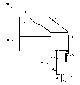
Figure 1 is a schematic illustration of an embodiment
of the present invention having a tool with a handle on
which a switch is mounted for controlling pressure to the
tool.
4

CA 02346571 2001-05-07
Figure 2 is a schematic illustration of an embodiment
of the present invention similar to the embodiment of
Figure 1, which further includes a quick disconnect.
Figure 3 is a schematic illustration of the presently
preferred embodiment of the invention in which the handle is
formed as a pistol grip.
Figure 4 is a schematic illustration of the presently
preferred embodiment of the hydraulic pressure supply and
its controls, according to the present invention.
BRIEF DESCRIPTION OF THE PRESENTLY
PREFERRED AND VARIOUS ALTERNATIVE
EMBODIMENTS OF THE INVENTION
Prior to proceeding to the much more detailed
description of the present invention, it should be noted
that identical components which have identical functions
have been identified with identical reference numerals
throughout the several views illustrated in the drawing
figures for the sake of clarity and understanding of the
invention.
Attention is directed to Figure 1, which schematically
illustrates an embodiment of the present invention.
Figure 1 illustrates an installation tool assembly,
generally designated 20, having a hydraulic connection 22,
preferably a hydraulic hose, for supplying hydraulic power
to an installation tool, generally designated 10.
Installation tool 10 includes a hydraulic cylinder 12,
a fixed jaw 14 and a moveable jaw 16. Additional detail

CA 02346571 2004-03-O1
regarding installation tool l0 is known in the prior art
and, therefore, is not described in further detail. For
example, an installation tool is provided in prior art
patent US 5,305,510.
Hydraulic hose 22 is attached to installation tool 10
by hose termination 24. The installation tool assembly 20
includes a handle, generally designated 70, having a switch
26 and a switch activation member 28. The switch 26 is
connected to signal connection 25. Switch 26 is employed to
turn on a source of hydraulic power, shown subsequently in
Figure 4. The hydraulic power causes relative movement of
jaws 14 and 16 for assembling a pair of workpieces (not
shown). Electrical and hydraulic supplies for installation
tool assembly 20 are shown in Figure 4.
Figure 2 illustrates an embodiment of the present
invention having a quick disconnect, generally designated
60, which includes each of a quick disconnect male side 32
and a quick disconnect female side 34. As in the embodiment
of Figure 1, the installation tool 10 includes a hydraulic
cylinder 12, a fixed jaw 14 and a moveable jaw 16.
Likewise, tool 30 has a handle 70 including a switch 26 and
switch activation member 28. Switch 26 is connected to
6

CA 02346571 2004-03-O1
signal connection 25. Hydraulic hose 22 is connected to
quick disconnect male side 32 by hose termination 24, the
quick disconnect female side 34 being attached to
installation tool 10.
Figure 3 illustrates the presently preferred embodiment
of the present invention. The installation tool assembly,
generally designated 40, includes installation tool 10
having hydraulic cylinder 12, fixed jaw 14 and moveable jaw
16.
Installation tool 10 is connected by quick disconnect
60 to a pistol grip handle, generally designated 50. Quick
disconnect 60 includes quick disconnect male side 32 and
quick disconnect female side 34. Switch 26 is contained in
handle 50 and switch activation member 28 is protected by
activation member guard 42. The purpose of activation
member guard 42 is to prevent inadvertent actuation of
installation tool 10.
Signal connection 25 is connected to switch 26.
Preferably, signal connection 25 is mechanically attached to
hydraulic hose 22 by ties 44.
Figure 4 illustrates schematically the general features
of the hydraulic pressure source, generally designated 80.
7

CA 02346571 2004-03-O1
Electrical power is supplied by electrical power line 52 and
electrical return line 54. Electrical lines 52 and 54 are
connected to input terminals 56 and 58 of low voltage supply
65, which provides low voltage power on low voltage
terminals 62 and 64. The low voltage power supplied by low
voltage power supply 65 may be either DC or AC. In one
preferred embodiment, the specific low voltage power
supplied by the low voltage power supply 65 is equal to or
less than about 12 volts. Low voltage line 74 is connected
to low voltage terminal 64. Low voltage line 66 is
connected to the low voltage terminal 62 and to the first
control terminal 68 of relay 65, and the second control
terminal 69 of such relay 65 is connected to low
7a

CA 02346571 2001-05-07
voltage fine 72. Low voltage lines 72 and 74, preferably,
are brought together as signal connection 25 and connected
to switch 26, which is shown in Figures 1, 2, and 3. When
switch activation member 28 is pressed, switch 26 is closed, ',
and low voltage current flows through the control side of
relay 65. This closes the conduction path inside relay 65
(not shown) to supply electrical power to motor power
terminal 88. Electrical current returns from electrical
motor 92 through power terminal 86 to electrical power
line 54.
When a person operates this system, he or she connects
electrical power to power terminals 52 and 62. The
installation tool 10 is then engaged with the workpieces
being assembled. The workpieces may, for example, be a tube
or pipe fitting, and a swage ring to force the fitting into
engagement with the tube or pipe.
when the workpieces are in place and the tool is
properly engaged with the workpieces, the operator presses
the switch activation member 28 to activate the installation
tool 10, and thereby assemble the workpieces.
While a presently preferred and various additional
alternative embodiments of the instant invention have been
described in detail above in accordance the patent statutes,
it should be recognized that various other modifications and
adaptations of the invention may be made by those persons
who are skilled in the relevant art without departing from
8

CA 02346571 2001-05-07
either the spirit of the invention or the scope of the
appended claims.

Dessin représentatif
Une figure unique qui représente un dessin illustrant l'invention.
États administratifs

2024-08-01 : Dans le cadre de la transition vers les Brevets de nouvelle génération (BNG), la base de données sur les brevets canadiens (BDBC) contient désormais un Historique d'événement plus détaillé, qui reproduit le Journal des événements de notre nouvelle solution interne.

Veuillez noter que les événements débutant par « Inactive : » se réfèrent à des événements qui ne sont plus utilisés dans notre nouvelle solution interne.

Pour une meilleure compréhension de l'état de la demande ou brevet qui figure sur cette page, la rubrique Mise en garde , et les descriptions de Brevet , Historique d'événement , Taxes périodiques et Historique des paiements devraient être consultées.

Historique d'événement

Description Date
Inactive : Périmé (brevet - nouvelle loi) 2021-05-07
Représentant commun nommé 2019-10-30
Lettre envoyée 2007-06-07
Inactive : CIB de MCD 2006-03-12
Accordé par délivrance 2004-10-12
Inactive : Page couverture publiée 2004-10-11
Lettre envoyée 2004-07-28
Inactive : Taxe finale reçue 2004-07-08
Préoctroi 2004-07-08
Inactive : Transfert individuel 2004-06-25
Lettre envoyée 2004-03-22
Un avis d'acceptation est envoyé 2004-03-22
Inactive : Approuvée aux fins d'acceptation (AFA) 2004-03-10
Modification reçue - modification volontaire 2004-03-01
Inactive : Dem. de l'examinateur par.30(2) Règles 2003-09-03
Inactive : Page couverture publiée 2002-04-05
Demande publiée (accessible au public) 2002-04-03
Inactive : CIB en 1re position 2001-07-18
Modification reçue - modification volontaire 2001-07-05
Inactive : Certificat de dépôt - RE (Anglais) 2001-06-07
Lettre envoyée 2001-06-07
Demande reçue - nationale ordinaire 2001-06-07
Exigences pour une requête d'examen - jugée conforme 2001-05-07
Toutes les exigences pour l'examen - jugée conforme 2001-05-07

Historique d'abandonnement

Il n'y a pas d'historique d'abandonnement

Taxes périodiques

Le dernier paiement a été reçu le 2004-03-08

Avis : Si le paiement en totalité n'a pas été reçu au plus tard à la date indiquée, une taxe supplémentaire peut être imposée, soit une des taxes suivantes :

  • taxe de rétablissement ;
  • taxe pour paiement en souffrance ; ou
  • taxe additionnelle pour le renversement d'une péremption réputée.

Les taxes sur les brevets sont ajustées au 1er janvier de chaque année. Les montants ci-dessus sont les montants actuels s'ils sont reçus au plus tard le 31 décembre de l'année en cours.
Veuillez vous référer à la page web des taxes sur les brevets de l'OPIC pour voir tous les montants actuels des taxes.

Titulaires au dossier

Les titulaires actuels et antérieures au dossier sont affichés en ordre alphabétique.

Titulaires actuels au dossier
LOKRING TECHNOLOGY, LLC
Titulaires antérieures au dossier
ALBERT A. MCKAY
Les propriétaires antérieurs qui ne figurent pas dans la liste des « Propriétaires au dossier » apparaîtront dans d'autres documents au dossier.
Documents

Pour visionner les fichiers sélectionnés, entrer le code reCAPTCHA :


Pour visualiser une image, cliquer sur un lien dans la colonne description du document. Pour télécharger l'image (les images), cliquer l'une ou plusieurs cases à cocher dans la première colonne et ensuite cliquer sur le bouton "Télécharger sélection en format PDF (archive Zip)" ou le bouton "Télécharger sélection (en un fichier PDF fusionné)".

Liste des documents de brevet publiés et non publiés sur la BDBC .

Si vous avez des difficultés à accéder au contenu, veuillez communiquer avec le Centre de services à la clientèle au 1-866-997-1936, ou envoyer un courriel au Centre de service à la clientèle de l'OPIC.


Description du
Document 
Date
(aaaa-mm-jj) 
Nombre de pages   Taille de l'image (Ko) 
Dessin représentatif 2002-01-27 1 5
Abrégé 2001-05-06 1 17
Description 2001-05-06 9 297
Revendications 2001-05-06 4 109
Dessins 2001-05-06 4 54
Dessins 2001-07-04 4 53
Description 2004-02-29 10 293
Revendications 2004-02-29 6 192
Courtoisie - Certificat d'enregistrement (document(s) connexe(s)) 2001-06-06 1 112
Certificat de dépôt (anglais) 2001-06-06 1 163
Rappel de taxe de maintien due 2003-01-07 1 106
Avis du commissaire - Demande jugée acceptable 2004-03-21 1 161
Courtoisie - Certificat d'enregistrement (document(s) connexe(s)) 2004-07-27 1 105
Correspondance 2004-07-07 1 36