Sélection de la langue

Search

Sommaire du brevet 2347333 

Énoncé de désistement de responsabilité concernant l'information provenant de tiers

Une partie des informations de ce site Web a été fournie par des sources externes. Le gouvernement du Canada n'assume aucune responsabilité concernant la précision, l'actualité ou la fiabilité des informations fournies par les sources externes. Les utilisateurs qui désirent employer cette information devraient consulter directement la source des informations. Le contenu fourni par les sources externes n'est pas assujetti aux exigences sur les langues officielles, la protection des renseignements personnels et l'accessibilité.

Disponibilité de l'Abrégé et des Revendications

L'apparition de différences dans le texte et l'image des Revendications et de l'Abrégé dépend du moment auquel le document est publié. Les textes des Revendications et de l'Abrégé sont affichés :

  • lorsque la demande peut être examinée par le public;
  • lorsque le brevet est émis (délivrance).
(12) Demande de brevet: (11) CA 2347333
(54) Titre français: SYSTEME ANTIVOL A L'ETALAGE ELECTROMAGNETIQUE
(54) Titre anglais: ELECTROMAGNETIC ANTI-SHOPLIFTING SYSTEM
Statut: Réputée abandonnée et au-delà du délai pour le rétablissement - en attente de la réponse à l’avis de communication rejetée
Données bibliographiques
Abrégés

Abrégé anglais


The present invention provides an antitheft system to detect the presence of
an
object which has a label affixed thereto when said object passes through a
surveillance zone comprising an oscillatory electromagnetic interrogation
field
having three separate and distinct vector components produced by driving the
transmitting coils located in housing on either side of said surveillance zone
with
an alternating power source repetitively in and out of phase with respect to
one
another so as to form magnetic lines of flux having one vector component in
the
out-of-phase mode. The signals generated by the label are received by coils in
said housing and are processed by electronic circuitry adapted to distinguish
said
label signals from spurious signals with a high degree of accuracy. The label
can
be deactivated so as to pass through the surveillance zone without triggering
a
system response.

Revendications

Note : Les revendications sont présentées dans la langue officielle dans laquelle elles ont été soumises.


What Is Claimed:
1. In a system for detecting the passage of an object through a surveillance
zone, the combination includes: means for detecting a signal generated by said
marker means in response to said generated oscillating magnetic lines of flux
within said surveillance zone; said detection means include circuitry for time
domain blanking and circuitry for signal recognition; said time domain
blanking
circuitry permits the entry to said signal recognition circuitry of said
signal
2A

generated by said ferromagnetic marker and received by said detection means
during a predetermined timed interval corresponding to said in-phase and out-
of-
phase mode switching and eliminates all other signals during all other time
periods from entry to said signal recognition circuitry; said signal
recognition
circuitry includes pulse width detection circuitry for detecting the pulse
width of
said signal generated by said ferromagnetic marker.
2. In detection apparatus, circuitry means associated with said transmitting
coil means for generating from said transmitting coil means an oscillating
magnetic field having a predetermined fundamental frequency; receiving coil
means mounted in said coil housing unit and adapted to receive signals
generated by a ferromagnetic marker means in response to said generated
oscillating magnetic field within said surveillance zone, whereby said
receiving
coil means is adapted to substantially eliminate said fundamental frequency
and
amplify said signals generated by said ferromagnetic marker means.
3. In a method for detecting the passage of an object through a surveillance
zone, including the step of detecting a signal generated by said ferromagnetic
marker in response to said generated oscillating magnetic lines of flux within
said
surveillance zone: said detection step is followed by the step of filtering
and
amplifying said signal generated from said ferromagnetic marker in said
oscillating magnetic interrogation field; said filtering and amplifying step
is
followed by the step of distinguishing said signal generated from said
ferromagnetic marker in said oscillating magnetic interrogation field from
other
signals by utilizing time domain blanking; said distinguishing step
distinguishes
the pulse width of signals generated from said ferromagnetic marker in said
oscillating magnetic field from other signals; said distinguishing step
includes the
step of correlating said signals generated by said ferromagnetic marker in
said
oscillating magnetic field; said detection step averages said signal generated
by
said ferromagnetic marker in said oscillating magnetic field.
3

Description

Note : Les descriptions sont présentées dans la langue officielle dans laquelle elles ont été soumises.

CA 02347333 2001-05-11
ELECTROMAGNETIC ANTI-SHOPLIFTING SYSTEM
Background To Invention
There are in existence several kinds of systems for detecting or preventing
the
theft of articles of value. One of these corresponds to U.S. Pat. No.
3,292,080
granted to E.M. Trikilis on December 13, 1966 which makes use of a
magnetometer and utilizes a magnetized object which identifies the article
unless
check-out procedure has removed the magnetism from the object.
Another system involves radioactive material which emits nuclear radiation.
When the label containing the magnetic material is removed from the
merchandise, the radiation is no longer emitted, and therefore radiation
detectors
situated in the doorway are not energized. On the other hand, if the radiation
emitters remain on the merchandise, doorway sensors of nuclear radiation
react,
and security personnel are in a position to prevent the theft. However, there
are
severe health problems with this system involving danger to people from the
nuclear radiation.
A further system involves the use of radio frequency generating device
imbedded
in a rubber pad. The radio frequency emitting device is fastened to articles
and if
not removed will energize radio frequency detecting antenna at the doorway. In
the normal course of events, when the merchandise is sold, a special fastener
is
unlocked and radio frequency emitter is removed from the article at the time
it is
sold, permitting the buyer to pass through the doorway without attracting the
attention of the store detectives.
The following United States patents illustrate a number of alternative
proposals
which will serve as background to the invention described and illustrated
herein
namely:

CA 02347333 2001-05-11
U.S. Pat. No. 3,631,442; U.S. Pat. No. 3,747,086; U.S. Pat. No. 3,754,228;
U.S.
Pat. No. 3,790,945; U.S. Pat. No. 3,820,103; U.S. Pat. No. 4,527,152; U.S.
Pat.
No. 4,888,579; U.S. Pat. No. 5,459,452; U.S. Pat. No. 5,602,556; U.S. Pad. No.
5,661,470.
Features Of The Invention
It is feature of this invention to provide an apparatus for detecting the
passage of
an object through a surveillance zone comprising a transmitting coil for
generating an oscillatory electromagnetic interrogation field within the
surveillance zone, a label secured to an object, whereby said label is adapted
to
cut or link up with the electromagnetic field during its traversal through the
electromagnetic interrogation field regardless of the label's special
orientation,
and thereby generating signals captured by a receiving coil including
electronic
circuitry adapted to set off an alarm.
More particularly, the electronic circuitry is adapted to minimize distortion
of the
generated signal by the label. The electronic circuitry is also adapted so as
to
differentiate label signals from other signals such as pop cans generating
lower
harmonics.
It is a further feature of this invention to provide people counting while
passing
through the interrogation zone.
It is another important feature, that the electronic circuitry has a memory to
be
able to store up to 256 alarms providing a detailed description of these
events,
including all main parameters of markers' signals as well as an exact day and
a
time of the events.
Brief Description Of Drawings
These and other objects and features will become apparent in the following
description to be read in conjunction with the sheets of drawings in which:
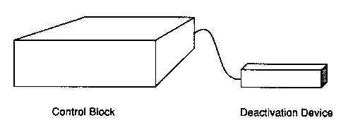
FIG.1 is a perspective view of the anti-shoplifting system.
FIG. 2 is a block diagram illustrating the various components of the
electronic
circuitry.

Dessin représentatif
Une figure unique qui représente un dessin illustrant l'invention.
États administratifs

2024-08-01 : Dans le cadre de la transition vers les Brevets de nouvelle génération (BNG), la base de données sur les brevets canadiens (BDBC) contient désormais un Historique d'événement plus détaillé, qui reproduit le Journal des événements de notre nouvelle solution interne.

Veuillez noter que les événements débutant par « Inactive : » se réfèrent à des événements qui ne sont plus utilisés dans notre nouvelle solution interne.

Pour une meilleure compréhension de l'état de la demande ou brevet qui figure sur cette page, la rubrique Mise en garde , et les descriptions de Brevet , Historique d'événement , Taxes périodiques et Historique des paiements devraient être consultées.

Historique d'événement

Description Date
Inactive : CIB de MCD 2006-03-12
Demande non rétablie avant l'échéance 2004-05-11
Le délai pour l'annulation est expiré 2004-05-11
Inactive : Demande ad hoc documentée 2004-02-13
Réputée abandonnée - omission de répondre à un avis sur les taxes pour le maintien en état 2003-05-12
Inactive : Page couverture publiée 2002-11-11
Demande publiée (accessible au public) 2002-11-11
Inactive : CIB en 1re position 2001-06-26
Inactive : CIB attribuée 2001-06-26
Inactive : Lettre officielle 2001-06-19
Demande reçue - nationale ordinaire 2001-06-13
Exigences de dépôt - jugé conforme 2001-06-13
Inactive : Certificat de dépôt - Sans RE (Anglais) 2001-06-13

Historique d'abandonnement

Date d'abandonnement Raison Date de rétablissement
2003-05-12

Historique des taxes

Type de taxes Anniversaire Échéance Date payée
Taxe pour le dépôt - petite 2001-05-11
Titulaires au dossier

Les titulaires actuels et antérieures au dossier sont affichés en ordre alphabétique.

Titulaires actuels au dossier
JEAN COURTOT
Titulaires antérieures au dossier
S.O.
Les propriétaires antérieurs qui ne figurent pas dans la liste des « Propriétaires au dossier » apparaîtront dans d'autres documents au dossier.
Documents

Pour visionner les fichiers sélectionnés, entrer le code reCAPTCHA :


Pour visualiser une image, cliquer sur un lien dans la colonne description du document. Pour télécharger l'image (les images), cliquer l'une ou plusieurs cases à cocher dans la première colonne et ensuite cliquer sur le bouton "Télécharger sélection en format PDF (archive Zip)" ou le bouton "Télécharger sélection (en un fichier PDF fusionné)".

Liste des documents de brevet publiés et non publiés sur la BDBC .

Si vous avez des difficultés à accéder au contenu, veuillez communiquer avec le Centre de services à la clientèle au 1-866-997-1936, ou envoyer un courriel au Centre de service à la clientèle de l'OPIC.


Description du
Document 
Date
(aaaa-mm-jj) 
Nombre de pages   Taille de l'image (Ko) 
Dessin représentatif 2002-10-16 1 4
Abrégé 2001-05-11 1 24
Description 2001-05-11 2 88
Dessins 2001-05-11 2 17
Revendications 2001-05-11 2 70
Page couverture 2002-11-01 1 34
Certificat de dépôt (anglais) 2001-06-13 1 163
Avis de rappel: Taxes de maintien 2003-02-12 1 115
Courtoisie - Lettre d'abandon (taxe de maintien en état) 2003-06-09 1 174
Deuxième avis de rappel: taxes de maintien 2003-11-13 1 113
Avis de rappel: Taxes de maintien 2004-02-12 1 116
Correspondance 2001-06-14 1 27