Note : Les descriptions sont présentées dans la langue officielle dans laquelle elles ont été soumises.
CA 02348044 2008-01-09
COMPACT PENDANT SPRINKLER HEAD
BACKGROUND OF THE INVENTION
The present invention relates to sprinklers used in automatic fire
extinguishing
systems for buildings and the like, and in particular, to a compact pendant
sprinkler head
assembly.
Sprinkler heads have long been used in automatic fire extinguishing systems
for
buildings and the like in order to disburse a fluid to suppress or extinguish
a fire. Typically,
the fluid utilized in such systems is water, although systems have been
developed to disburse
foam and other materials. Historically, sprinkler heads include a solid metal
base connected
to a pressurized water source, and a deflector intended to alter the
trajectory of the water and
distribute the water spray pattern over a controlled area. The deflector is
typically spaced
from the base outlet, and a fusible trigger assembly secures a seal over the
base outlet. When
the temperature about the sprinkler head is elevated to a preselected
temperature indicative of
a f ire, the fusible trigger assembly releases the seal, and water flow is
initiated through the
sprinkler head. The water ejected from the sprinkler head impacts the
deflector, resulting in a
preselected water distribution pattern which descends upon the fire.
One common sprinkler head design is a pendant sprinkler head, whereby the
sprinkler
head. is positioned in a downward direction towards the floor of the
controlled area. With
such pendant sprinkler heads, normally, the deflector is positioned a
preselected distance
below the outlet of the sprinkler body, and is secured to a pair of arms
extending away from
outlet of the sprinkler body. In response to the activation of the fusible
trigger assembly, the
sealing assembly falls away from the sprinkler body, allowing water to be
transported
through the sprinkler body in a downward direction towards the deflector.
The deflector in many current pendant sprinkler head designs is positioned a
fixed
distance from the outlet of the sprinkler body, and thereby increases the size
of the sprinkler
head. Furthermore, in many applications, aesthetic considerations demand that
the sprinkler
body is compact and relatively unnoticeable. In addition, many applioations
require an
effective, compact sprinkler head in order to maximize space utilization.
Current pendant
1
CA 02348044 2001-05-17
sprinkler heads are generally incapable of being used undei- such conditions,
as the size and
particular structural configuratiori yields a sprinkler head which is
conspicuously noticeable,
as well as relatively large.
In response, the industry has advanced pendant sprinkler heads which are
designed to
be recessed within a ceiling or other wall. These recessecl pendant sprinklers
often include a
deflector positioned between the fusible trigger assembly and the outlet of
the sprinkler.
Upon separation of the fusible trigger assembly, the water pressure travelling
through the
orifice of the sprinkler head moves the deflector a preselected distance away
from the outlet.
The deflector is normally attached to two or more verticallv extending rods or
pins slidably
received by apertures formed in a flange or rim projecting from the exterior
surface of the
sprinkler head. The free end of each pin is formed with an increased diameter,
and thus, as
the water pressure forces the deflecitor away from the outlet, the pin ends
abuttingly contact
the flange or rim to hold the deflector in place.
The use of pins to enable the deflector to move a preselected distance from
the outlet
upon activation of the sprinkler head, and the flanges or rim into which they
are slidingly
positioned have certain disadvantages. The pins, as they are external to the
sprinkler body
can gather dust, particulate matter, or fluids residing within the wall or
ceiling into which the
pendent sprinkler head is attached. This dirt and debris mav collect within
the apertures
formed within the flange or rim and. prevent the efficient and smooth movement
of the pins
through the aperture in response to a f re, and in consequence, prevent the
proper operation of
the sprinkler head. In addition, the pin receiving flanges or rim projecting
from the sprinkler
body necessarily requires the cavity of the wall or ceiling into which the
sprinkler is placed to
be larger in diameter. That is, to enable clearance of the riin or flange, the
hole through
which the pendent sprinkler head is inserted must be larger. This in turn
prevents such
pendent sprinkler heads from being used in environments wherein efficient use
of space is
required.
Accordingly, there exists a need for a high volume pendant sprinkler head
which is
compact to thereby enable use in applications wherein effective space
utilization must be
observed.
SUIVIMARY OF THE INVENTION
2
CA 02348044 2009-09-08
In one embodiment, the present invention overcomes the difficulties confronted
by the
prior art by providing a compact sprinkler head having a deflector assembly
positioned within
a body extension of the sprinkler head. According to one preferred aspect of
the invention
there is provided a sprinkler head for a fire extinguishing system comprising:
a sprinkler body having an orifice, said orifice defining an inlet and an
outlet;
a body extension attached to said sprinkler body and having an extending
section
extending below said outlet of said sprinkler body;
a retaining member positioned below said outlet and within said body
extension, said
retaining member mounted to be movable relative to said body extension and
said sprinkler
1 o body;
a deflector movable between an activated position and a storage position
within said
body extension and having at least two support arms projecting therefrom, said
retaining
member coupled to said support arms at a fixed distance from said deflector,
said support
arms movably disposed within said body extension, wherein said deflector and
said retaining
member are positioned within said body extension when in said storage
position;
a sealing assembly configured to sealingly engage said outlet of said
sprinkler body,
said sealing assembly movable from a closed position wherein said sprinkler
head is inactive
to an open position wherein said sprinkler head is activated; and
a trigger assembly carried by said body extension and operably connected with
said
sealing assembly and said deflector, wherein said retaining member is captured
and halted by
said extending section of said body extension when said sprinkler head is
activated and said
deflector is deployed to its extending position.
Configuring a sprinkler head to have a deflector movably positioned within a
frame
results in a compact sprinkler head which may be used in applications where
space
constraints must be observed, and eliminates the need for support pins
attached to the
deflector and residing external to the sprinkler body.
According to another preferred aspect of the invention, the deflector is
monolithically
formed with its support arms.
Providing a deflector positioned within the body extension reduces the
diameter of the
sprinkler head, while monolithically forming the deflector and the support
members decrease
its manufacturing cost.
3
CA 02348044 2009-09-08
According to yet another preferred aspect of the invention, a body extension
is formed
with an extending section having an annular rim while an annular retaining
member, attached
to a deflector, is slidably positioned within the body extension and captured
by the annular
rim. The sprinkler head includes a sprinkler body, and the body extension
attached to the
sprinkler body. The annular retaining member is positioned beyond the bottom
of the
sprinkler body, within the body extension, and has an outer periphery formed
with at least
one notch and a diameter greater than the diameter of the inwardly extending
annular rim.
The deflector is positioned within the body extension and has at least one
support arm
projecting therefrom. The support arm has an upper region dimensioned for
receipt by the
notch formed in the annular retaining member. A sealing assembly is configured
to sealingly
engage the outlet of the sprinkler body while a trigger assembly is carried by
the body
extension and operably connected with the sealing assembly. Providing an
annular retaining
member formed with notches for attachment to the deflector provides an
effective and
reliable structure without the use of externally mounted deflector pins.
Additionally, the
annular retaining member which is captured by the annular rim provides a
reliable structure
for moving the deflector to a preselected position upon activation of the
sprinkler head.
These and other advantages, benefits and objects will be understood by one
with
ordinary skill in the art from the drawings, description and claims which
follow.
4
CA 02348044 2009-09-08
BRIEF DESCRIPTION OF THE DRAWINGS
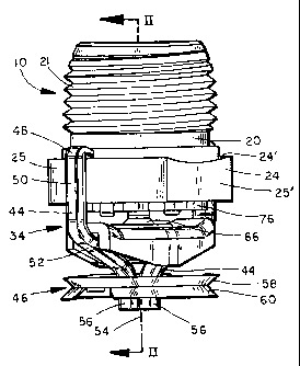
FIG. 1 is a perspective view of the pendant sprinkler head embodying the
present
invention;
FIG. 2 is a cross sectional view of the sprinkler head depicted in FIG. 1,
taken along
the line II-II of FIG. 1;
FIG. 3 is a bottom perspective view of the sprinkler head depicted in FIGS. 1
and 2;
FIG. 4 is a cross sectional view of a sealing member embodying the present
invention;
FIG. 5 is a bottom view of the deflector support assembly embodying the
present
invention;
FIG. 6 is a side view of the deflector support assembly depicted in FIG. 5;
FIG. 7 is a perspective view of a retaining ring embodying to the present
invention;
FIG. 8 is a perspective view of a deflector plate according to a preferred
embodiment
of the invention;
FIG. 9 is a top view of a deflector plate according to an alternative
preferred
embodiment of the invention;
FIG. 10 is a side view of the deflector plate depicted in FIG. 9;
FIG. 11 is a bottom perspective view of a lever bar of a preferred embodiment
of the
present invention;
FIG. 12 is a side view of a lever arm of a preferred embodiment of the present
invention;
FIG. 13 is a perspective view of a compression pin of a preferred embodiment
the
present invention;
FIG. 14 is a perspective view of the sprinkler head depicted in FIGS. 1 and 2,
illustrated in the activated position;
FIG. 15 is a bottom perspective view of the sprinkler head depicted in FIG.
14;
FIG. 16 is a perspective view of a sprinkler head according to an alternative
preferred
embodiment of the present invention;
FIG. 17 is a sectional view of a sprinkler body of a preferred embodiment of
the
present invention;
5
CA 02348044 2001-05-17
FIG. 18 is a bottom perspective view of a sprinkler body according to an
alternative
preferred embodiment of the present invention;
FIG. 19 is an exploded, perspective view of a sprinkler body according to
still another
alternative preferred embodiment of'the present invention;
FIG. 20 is a sectional side view of the sprinkler head of FIG. 19, illustrated
in the
inactive state, with the escutcheon and cover plate explodeci from the frame;
FIG. 21 is a sectional side view of the sprinkler head of FIGS. 19 and 20,
with the
spri.nkler head illustrated in the active state;
FIG. 22 is a detailed view of the retaining menlber and deflector of a
preferred
embodiment of the present invention;
FIG. 23 is a plan view of the cover plate; and
FIG. 24 is a side view of the cover plate of FIG. 23.
DETAILED DESCRIPTION OF THE PREFERRED EMBODIMENTS
The present invention is embodied in a pendant sprinkler head, referred to
generally
by reference numeral 10. The present invention provides a sprinkler head which
by its
structure is compact and reliable. Furthei-more, given the decreased size and
compact nature
of the present invention, it is particularly suited for applications wherein
it is desired to have
a sprinkler head which may be recessed in a ceiling and/or have a reduced
visibility to
thereby maintain the aesthetic appearance of the environment in which it is
used, for
example, in residential applications.
Referring now to FIGS. I through 18, sprinkler head 10 includes a sprinkler
body 20
having an upper region 21 which is preferably extei-nally threaded so as to
allow removable
attachment of sprinkler body 20 to a piping system (not shown). Positioned
below upper
region 21 is a flange or rim 24. Preferably, as shown in FIG. 18, rim 24 has a
pair of opposed
arcuate sections 25, and a pair of opposed linear sections 25'. Sprinkler body
20 is formed
having a cavity 26 with an inlet orifice 28 (FIGS. 2 and 17) and opposing
outlet 30. Outlet
has a larger diameter than cavity 26, and hence defines an annular shoulder
23, while inlet
orifice 28 includes an annular shoulder or seat 29 projecting within cavity 26
(FIGS. 2 and
17). Annular shoulder or seat 29 fu.rther includes an annular groove 29' (FIG.
17).
30 Positioned substantially within cavity 26 of sprinkler body 20 is a
deflector assembly
22. A trigger assembly 34 engages exterior 24' of sprinkler body 20 and
extends below, but
in close proximity to, outlet 30 of sprinkler body 20. A sealing member 36 is
placed in fluid
tight engagement with seat 29 of sprinkler body 20.
6
CA 02348044 2001-05-17
Sealing member 36, as shown most clearly in FIG. 2 and 4, is preferably a
spring disk
having an internal bias in a direction towai-ds outlet 30 of sprinkler body
20. The spring force
of sealing member 36 assures that upon activation of sprinkler body 20,
sealing member 36
will spring in a direction towards outlet 30, to thereby urge a sealing
assembly 98 from
central cavity 26. Under surface 40 of sealing member 36 is preferably formed
having an
arcuate dome or protuberance 42. the purpose of which will be described in
detail below.
Trigger assembly 34 includes a pair of lever arms 44 and a fusible link 46.
Lever
arms 44 include an upper curved attachment section 48 integrally attached to a
generally
vertical member 50. Vertical member 50 isjoined to an iiiwardly curved section
52, curved
generally towards the vertical axis of sprinkler body 20, as indicated by
dotted line 54 of FIG.
1. Inwardly curved section 52 is joiined to a generally vertical fusible link
attachment end 56.
Received within ends 56 of lever arms 44 is a fusible link 46. Preferably,
fusible link 46
includes a pair of plates 58 and 60 joined by a layer of fusible material. As
shown most
clearly in FIG. 3, each plate 58, 60 is fonned with a radial channel 62 which
is greater in
length than the radius of plate 58., 60 so that when plates 58 and 60 are in
the assembled
condition, a central aperture 64 is formed for receipt of ends 56 of lever
arms 44. Ends 56 of
lever arms 44 are placed in spaced relation within center aperture 64 such
that a loading
member 66, and its adjustment tool (not shown), may be placed therethrough.
Each plate 58, 60, may further be formed with one or more protuberances 68 and
one
or more indentations 70. Protuberances 68 and indentations 70 are formed in
plates 58, 60
such that when assembled, protuberances 68 of one plate 58, 60 are in registry
with
indentations 70 of the other plate 58, 60. Each protuberance 68 is formed with
an aperture
68'. The presence of protuberances 68 arid indentations 70 promote the timely
separation of
plates 58, 60 upon experiencing a preselected elevated temperature. Each plate
58, 60 may
be further formed with a peripheral flange 72 such that when assembled, flange
72 of plate 58
extends in a direction opposite to the direction of flange 72 of plate 60.
Deflector assembly 22 includes a deflector support assembly 74 attached to a
deflector plate 76. Deflector support assembly 74 includes an annular cage or
ring 78
dimensioned to be slidingly received within cavity 26. Annular ring 78 has
depending
therefrom at least one, and preferably two oi- more, deflector attachment arms
80 secured at
end 82 to deflector plate 76. As shown in FIG. 6, end 82 of'each deflector
attachment arm 80
has a tapered section 83 and terminates in a bulb 84. Tapered section 83
permits each
deflector attachment arm 80 to be received by an attachmetit aperture 86
formed in deflector
7
CA 02348044 2001-05-17
plate 76, while bulb 84 prevents detachment of deflector plate 76 from
deflector attachment
arms 80 once secured thereto.
Deflector plate 76 includes a plurality of slots 88 extending inwardly from
periphery
87. Preferably, slots 88 extend inwardly in a radial pattei-n and are wedge
shaped. A central
aperture 90 is formed in deflector plate 76. In an alternative preferred
embodiment, as shown
at FIGS. 9, 10, and 16, a deflector 76' includes a periphery 87' which is
curved in a direction
toward inlet orifice 28 of sprinkler body 20. Furthermore, cleflector 76'
contains a plurality of
generally keyhole shaped slots 88' positioned in space relation about the
periphery 87', and
extending inwardly in a radial pattern. The curved periphery 87', along with
keyhole shaped
slots 88' are believed to result in an optimum water distribution pattern to
thereby effectively
control a fire. Annular ring 78, deflector attachment arms 80, and deflector
plate 76 may be
monolithic.
When in assembled condition, deflector 76 or 76', is positioned in close
proximity to
outlet 30. Preferably, at least a portion of deflector 76, 76' resides within
outlet 30. In
addition, annular ring 78 will be positioned adjacent to sealing member 36 and
against
annular shoulder 29", all within cavity 26. As shown in FIGS. 2, 7, and 15,
positioned
within central cavity 26, and proxirriate to outlet 30, is a retaining ring
92. Retaining ring 92
is held at outlet 30 and is positioned against shoulder 23. Retaining ring 92
is secured at
outlet 30, for example, by crimping exterioi- surface 31 of outlet 30 about
retaining ring 92.
As shown in FIG. 7, retaining ring 92 includes an inner surface 94 formed
having a pair of
slots 96. Slots 96 are dimensioned t;o slidingly receive deflector attachment
arms 80 therein.
Inner surface 94 of retaining ring 92 has a diameter which is less than the
outer diameter of
annular ring 78. This smaller diameter of inner surface 94 of retaining ring
92 enables
retaining ring 92 to act as a stop to thereby prevent the expulsion of
deflector 76 beyond a
preselected distance from outlet 30 upon activation.
The sealing assembly includes sealing member 36, a compression pin 98, and a
lever
bar 100. Lever bar 100 is composed of a bridge member 102, having ends 102'
slanted
towards outlet 30 of sprinkler head 20, and a pair of generally orthogonally
projecting side
members 104. Side members 104 are placed in space relation such that when in
the
assembled condition, ends 102' of bridge member 102 rest on inner surface 53
of inwardly
curved section 52 of lever arms 44. Lever bar 100 includes a central aperture
106 which is
internally threaded and dirnensioned to threadingly receive loading member 66,
which is
preferably a loading screw.
8
CA 02348044 2001-05-17
Compression pin 98 is a generally vertical member having opposing ends 110 and
112. Compression pin 98 is slidingly received by a central aperture 90 formed
in deflector 76
or 76'. End 112 of compression pin 98 includes an annular- rim 114. Annular
rim l 14 has a
diameter greater than the diameter of central aperture 90 of deflector 76 or
76', and thereby
prevents compression pin 98 froni being separated froni deflector 76 or 76'.
To assemble sprinkler head 10, sealing member 36 is first placed in abutting
contact
with seat 29, formed in inlet orifice 28. Deflector support assembly 74 is
then placed within
cavity 26, with annular ring 78 contacting surface 29". Thereafter, retaining
ring 92 is placed
in contact with shoulder 23, and exterior surface 31 crimped about retaining
ring 92 to hold
the same in position. Once retairiing ring 92 is in position, deflector plate
76 or 76' is
attached to ends 82 of deflector attachment arms 80. Thei-eafter, lever anns
44 are placed in
contact with rim 24, with attachment section 48 being supported by inner
surface 24'.
Preferably, inner surface 24' of rim 24 is sloped in a downward direction,
while attachment
section 48 of lever arms 44 are curved in a downward direction to thereby
engage sloped
inner surfaces 24'. The sloped inner surface 24', and downwardly curved
attachment sections
48, assure that lever arms 44 are maintained in proper position. Preferably,
as depicted in
FIG. 18, rim 24 is formed with a pair of slots 24". Slots 24" are each
dimensioned to receive
a vertical section 50 of lever arm 441, to thei-eby decrease the diametrical
space utilized by
sprinkler head 10.
Once lever arms 44 are secured to the extenor of sprinkler body 20, lever bar
100 is
placed between lever arms 44 and outlet 30 of sprinkler body 20, while fusible
element 46 is
attached to ends 56. Thereafter, loading menlber 66 is placed through center
aperture 64 of
plates 58, 60 and threaded within center aperture 106 of lever bar 100.
Rotation of loading
member 66 within center aperture 106 urges lever bar 100 in a downward
direction, placing
lever arms 44 in tension, which in turn assw-es vigorous separation once
fusible element 46
experiences a preselected temperature. In addition, rotation of loading member
66 within
central aperture 106 causes compression pin 98 to move in a direction toward
orifice 28 and
within cavity 26, with end 112 eventually contacting protuberance 42 formed in
undersurface
40 of sealing member 36. Continued rotation of loading member 66 forces
sealing member
36 into annular groove 29' of anrrular seat 29, and thereby assures a fluid
tight seal between
sealing member 36 and inlet orifice 28.
In an alternative prefer-red embodiment, as shown in FIG. 16, a lever bar 100'
is a
generally flat plate having an intenial spring force directed towards outlet
30 of sprinkler
9
CA 02348044 2001-05-17
body 20. Opposing ends 116 and 118 of lever bar 100' each include a notch 120
dimensioned
to receive a lever arm 44. Thus, when loading member 66 is rotated in upward
direction
through central aperture 106, lever bar 100' is drawn in a downward direction,
thereby
placing lever arms 44 into tension.
In operation, when fusible element 46 experiences a preselected temperature
due to
the presence of fire, plates 58 and 6O will separate, releasie- lever arms 44
and lever bar 100
or 100'. As lever arms 44 and lever bar 100, or 100' fall away from outlet 30
of sprinkler
body 20, the compressive force upon compression pin 98 is released. The water
pressure
acting on sealing member 36, as well as the internal spring force of sealing
member 36,
causes sealing member 36 to be thrust in a downward direction through cavity
26 and be
expelled through outlet 30. As sealimg member 36 is urged in a direction
towards outlet 30,
annular ring 78 will also move towards outlet 30 until abutting contact is
made between
annular ring 78 and retaining ring 9:2..
When abutting contact is rnade between retaining ring 92 and annular ring 78,
as
shown on FIG. 15, deflector plate 76 or 76' will be positioned a preselected
distance beyond
outlet 30 and be held at such distance by deflector attachment arms 80 while
rim 114 of
compression pin 98 will abuttingly contact surface 76" of deflector plate 76
or 76'. Sealing
member 36, having an outer dimension less than the inner- ctimension of
annular ring 78, will
be expelled from outlet 30 of sprinkler body 20. As shown in FIG. 5, inner
surface 78' of
annular ring 78 preferably includes an inwardly projectin~, horizontal pin 79.
As sealing
member 36 is being expelled from cavity 26, it will hit horizontal pin 79.
Contact between
horizontal pin 79 and sealing member 36 causes sealing member 36 to rotate
about a
horizontal axis and alters its linear trajectory. This in turn prevents
sealing member from
coming to rest on surface 76" of cleflector plate 76, 76' and interfering with
the operation of
sprinkler head 10. Once sealing member 36 f'alls away from outlet 30, water
will flow
through central orifice 26 and be deflected in an optimtuII pattern by
deflector plate 76 or 76'
in order to extinguish or suppress a fire.
In a preferred embodiment, the height of sprinkler body 20 is less than or
equal to
approximately 1.0 inches, while the diameter of cavity 26 is no greater than
approximately
0.625 inches. Also, preferably, outlet 30 has a diameter less than or equal to
approximately
0.760 inches while inlet orifice 28 has a diameter less than or equal to 0.450
inches, and the
diameter defined by groove 29' of annular seat 29 is less than or equal to
approximately 0.530
inches. In the preferred embodin-rent, the diameter defined by arcuate
sections 25 of rim 24 is
CA 02348044 2001-05-17
less than or equal to approximately 0.930 inches, with the angle defined by
inner surface 24'
of annular rim 24 is approximately 25 off the horizontal, while the distance
between linear
sections 25' is approximately 0.880 inches. Also preferably, the diameter of
deflector plate
76, 76' is less than or equal to approximately 0.740 inches.
In the most preferred embodiment:, the height of sprinkler head 10 is
approximately
0.900 inches, and the diameter of orifice 26 is between approximately 0.618
and 0.613
inches. Also most preferably, the d:iameter clefined by arcuate sections 25 of
rim 24 is
approximately 0.920 inches, while the distance between linear sections 25' is
approximately
0.875 inches, and the diameter defirieci by groove 29' of annular seat 29 is
approximately
0.525 inches. Also, most preferably, the diameter of outlet 30 is between
approximately
0.754 and 0.750 inches, while the diiameter of deflector 76, 76' is
approximately 0.730 inches.
Referring now to FIGS. 1':) through 23, according to an alternative preferred
embodiment, a sprinkler head 100 includes a sprinkler bodv 110 having an
externally
threaded upper region 112 and an externally threaded lower region 114. A rim
116 projects
from sprinkler body l 10 between upper region 112 and 1wver region 114.
Externally
threaded upper region 112 allows removable attachment of sprinkler body 100 to
a piping
system (not shown) in fluid communication with a source of fire extinguishing
fluid.
Sprinkler body 110 includes a central orifice 118 having an inlet 120 and an
outlet 122.
Bottom 124 of sprinkler body 1 10 is fornied with an annular shoulder or
counterbore 126.
A generally cylindrical body extension 128 is threadably attached to lower
region 114
of body 110. Extending section or lower i-egion 132 of body extension 128 is
positioned
beyond bottom 124 of sprinkler body 110 and is formed with an inwardly
extending member
134 (FIGS. 19 through 21). Inwardly extending member 134 is preferably an
annular rim
135, but may also be, for example, two or more projections extending from
inner surface 133,
and diametrically opposed.
Positioned within central channel 138 of body extension 128 is a deflector
assembly
140. Deflector assembly 140 includes a deflector plate 142 positioned a
preselected distance
from bottom 124 of sprinkler body 110 by a plurality of support arms 144.
Support arms 144
are received by a retaining member 149. Deflector plate 142 includes a
plurality of tines 146
positioned about the periphery of'deflector plate 142 and spaced a preselected
distance apart.
Tines 146 project in a direction towards bottom 124 of sprinkler body 110. A
central
aperture 148 is formed in deflector plate 142. Support ar7ns 144 include a
central section 150
having a generally triangular shape and a bottom region 152 which is generally
linear. The
I1
CA 02348044 2001-05-17
w of bottom region 152 is preferably no greater than the width of each
individual tine
146. Formed in upper section 154 are a paii- of notches oi- cutouts 156 which
collectively
define a neck 158 therebetween. Preferably, deflector plate 142 and support
arms 144 are
monolithically formed in a unitary construction by any method commonly
utilized in the art.
For example purposes only, a planar sheet of suitable material may be stamped
or punched to
form cut lines and bend lines outlin;ing deflector plate 142 and support arms
144. Thereafter,
the sheet of material is cut along the cut lines and subsequently bent along
the bend lines by
standard bending techniques to forni deflectoi- plate 142 and support arms
144. As seen most
clearly in FIG. 22, support arms 144 flare slightly outward such that upper
sections 154
collectively define a diameter greater than the diameter of deflector plate
142.
Retaining member 149 is preferably an annular ring with a central opening 160
in
registry with central orifice 118 of sprinkler body 110. Outer periphery 162
of retaining
member 149 includes a plurality of notches 164. The number of notches 164
formed in
periphery 162 corresponds to the number of support arms 144 projecting from
deflector plate
142. Each notch 164 is dimensioned to geometrically receive neck 158 of a
support arm 144.
As shown in FIG. 20, when support arms 144 are received by notches 164, ends
145 of
support arms 144 are positioned between retaining member 149 and bottom
surface 124 of
sprinkler body 120, with ends 145 either in abutting contact with bottom
surface 124, or in
proximity thereto.
Positioned below deflector plate 142 is a lever disk or biasing member 166.
Biasing
member 166 is formed with a central, intei7ially threaded aperture 168. A
trigger assembly
170 is carried by inwardly annular r-ini 135 of body extension 128 and
includes a pair of
levers 172 which are operably connected to a thermally sensitive trigger
mechanism 174.
Ends 176 of levers 172 are supported by inner surface 136 of annular rim 135.
Levers 172
depend below body extension 128 with ends 178 received by thermally sensitive
trigger
mechanism 174. Thermally sensitive trigger mechanism 174 is known in the art
and
generally comprises one or more plates 179, 180 joi.ned by a heat fusible
material. Plates
179, 180 are each formed with a lever receiving aperture 181 which receives
and holds ends
178 of levers 172 in a closed position, and a central aperture 181.
To seal outlet 122, a sealing assernbly 182 includes an actuator rod 184 and
an
annular sealing ring 186. As best seen in FIG. 20, actuator rod 184 includes a
first annular
rim 188 and a second annular rim 190, with first rim 188 having a larger
diameter than rim
190. End 192 includes a circular channel 194 terminating a preselected
distance within the
12
CA 02348044 2001-05-17
interior of actuator rod 184. Preferably, sealing ring 186 is a compression
spring having an
outer diameter greater than the diarneter of outlet 122, but less than the
diameter of counter
bore 126. Sealing ring 186 includes a ceritral opening 187 which is
approximately the same
diameter as the diameter of end 196 of actuator rod 184.
Slidably positioned over exterior surface 129 of body extension 128 is an
escutcheon
198. Escutcheon 198 flares slightly outwardly and includes an annular rim 200
having an
outer diameter greater than the diameter of the cavity into which sprinkler
head 100 is
positioned. Rim 200 of escutcheon 198 includes a plurality of pairs of notches
202. Each
pair of notches 202 define a contact surface 204 therebetween. Escutcheon 198
includes a top
section 199 and a outwardly tapered. section 199'. To attacli escutcheon 198
to body
extension 128, escutcheon 198 is slidingly placed over exterior 129 until top
edge 199"
contacts stop member 131 formecl on exterior surface 129 of body extension
128. The
diameter of top section 199 is slightly greater than the outer diameter of
body extension 128
to thereby provide a friction fit between escutcheon 198 and body extension
128.
A cover plate 206 is attached to annular rim 200 of escutcheon 198 and
includes a
generally circular planar center sect:ion 208 and a peripheral rim 210
projecting in the
direction of annular rim 200. Edge 212 of peripheral rim 2 10 includes a
plurality of
mounting members 214. Each mounting member 214 includes a generally planar
center
section 216 connected to a pair of side members 218 projecting towards inner
surface 211 of
cover plate 206. As shown most clearly in FIG. 23, mounting members 214 extend
inwardly
towards the center of cover plate 206. Cover plate 206 expresses a diameter
greater than or
equal to the center opening 200a of escutcheon 198 to thei-eby conceal from
view the interior
of sprinkler head 100. As shown in FIG. 24, center sections 216 of mounting
members 214
are located in a plane spaced froni the plane defined by upper edge 212 of
peripheral rim 210.
Cover plate 206 is attached to annular rim 200 of escutcheon 198 by placing a
fusible
material between center sections 216 of niounting members 214 and contact
surfaces 204 of
annular rim 200. As center sections 216 lie in a plane above the plane defined
by edge 212,
an interstice is formed between annular rim 200 and cover plate 206 to thereby
enable the
passageway of air towards thermally sensitive trigger mechanism 174.
Referring to FIGS. 19 and 20, an ejector spring 220 is positioned between
annular rim
200 of escutcheon 198 and inner surface 211 of cover plate 206. Ejector spring
220 includes
a first section 222, and a second section 224 joined by an ai-cuate bridge
section 226. First
section 222 has a greater length than second section 224, while bridge member
226 may be
13
CA 02348044 2001-05-17
formed with a cutout section 228. First section 222 and second section 224 are
each formed
with a curved lip 230, both of which extend in the same direction. When in
position, curved
lip 230 of first section 222 is positioaried in contact with outer edge 203 of
annular rim 200,
while second section 224 is positioned in abutting contact with cover 206.
When cover 206
is attached to annular rim 200, second section 224 of ejector spring 200 is
urged towards first
section 222 to thereby place ejector spring 200 in compression. Upon the
fusing of the
fusible material positioned between annular rim 200 and cover 206, ejector
spring 220 is
released from compression and forc:es cover 206 away from annular rim 200.
To assemble sprinkler head 100, levers 172 are placed within body extension
128 so
as to be supported by annular --im 135. Ends 178 of levers 172 are then placed
within
apertures 181 of thermally sensitive trigger nlechanism 174. Once thermally
sensitive trigger
mechanism 174 is attached to levers 172, biasing member 166 is placed over
pins 172 and
within body extension 128. Thereafter, necks 158 of support arms 144 are
placed within
notches 164 of retaining member 149. Sealing ring 186 is then placed in
abutting contact
with rim 190 of actuator rod 184, while actuator rod 184 is placed within body
extension 128,
with end 192 extending through central aperture 148 of deflector plate 142.
Thereafter, body
extension 128 is rotatably connected to sprinkler body 1 10 by rotating body
extension 128
into externally threaded lower region 114 of body 1 10 until abutting contact
is made between
body extension 128 and rim 117.
As best seen in FIG. 20, a coinpression member 240, such as, for example, a
compression screw, is placed through central aperture 181 of thermally
sensitive trigger
mechanism 174, and central aperCut-e 168 of biasing member 166. Compression
member 240
includes an externally threaded region 232, and a region of reduced diameter
234
dimensioned to be received by charinel 194 of actuator rod 184. Compression
member 240 is
placed through central aperture 181' of thennally sensitive trigger mechanism
174 and rotated
within internally threaded aperture 168 of lever biasing member 166 to urge
pins 172 in an
outward direction, thereby securing pins 172 to thermally sensitive trigger
mechanism 174.
In addition, the rotation of conlpression member 240 provides a force upon
actuator rod 184
which in turn urges rim 190 of actuator rod 184 in a direction towards inlet
120 of body 110.
This force places sealing ring 18Ei finnly within counter bore 126 and fluidly
seals outlet 122
of body 110. Once compression member 240 is threadably secured in channel 194
of
actuator rod 184, sprinkler body 118 and body extension 128 are inserted
within the cavity
and rotatably affixed to a piping system (not shown). Thereafter, cover 206 is
attached
14
CA 02348044 2001-05-17
annular rim 200 of escutcheon 198 as detailed above, and thereafter slidingly
placed about
exterior 129 of body extension 128.
In the inactive state, ends 145 of support arms 144 will be in abutting
contact with
bottom surface 124 or in proximity thereto, and above upper surface 149' of
retaining
member 149. Bottom surface 14 2' of deflector plate 142 may be in abutting
contact with top
surface 166' of lever biasing member 166 or spaced slightly thereabove.
When the teinperature surrounding sprinkler head 100 increases due to the
presence of
fire, heated air will travel through the interstice formed between annular rim
200 of
escutcheon 198 and cover plate 206 and contact both thermally sensitive
trigger mechanism
174 and the fusible material positioned between cover plate 206 and annular
rim 200.
Exhaustion of heated air from body extension 128 is achieved by at least one
exhaust slot 235
formed above stop member 131. Once the fusible material between plates 179,
180 of
thermally sensitive trigger mechanism 174 and cover plate 206, and annular rim
200 reaches
a preselected temperature, cover plate 206, will separate and be forced in a
direction away
from body extension 128 by ejector spring 220. Additionally, levers 172 will
be released
from tension thereby enabling plates 179 and 180 of thermally sensitive
trigger mechanism
174 to drop away from body extension 128. When this occurs, sealing ring 186
will urge
actuator rod 184 in. a direction through body extension 128 and out of sealing
engagement
with outlet 122 of sprinkler body 120. As the diameter of annular flange 188
is greater than
the diameter of central aperture 148 of deflector plate 142, a section of
actuator rod 184 will
extend beyond deflector plate 142, while end 196 will be captured by deflector
plate 142
(FIG. 21). The pressure of fluid traveling through central orifice 118 and the
ejection force
caused by sealing member 186, will nzove deflector assenlbly 140 in a
direction away from
outlet 122, and towards inwardly extending member 134 of body extension 128.
As the
diameter of retaining member 149 is greatei- than the diameter of inwardly
extending member
134, inwardly extending member 134 arrests the movement of retaining member
149,
enabling deflector plate 142 to extend beyond body extension 128 and be held
at a fixed
distance from inwardly extending niember 134. Fire extinguishing fluid is then
expelled
from central orifice 118 and travels through body extension 128 and is
thereafter deflected in
an optimum pattern by deflector plate 142 in an attempt to extinguish or
control a fire.
It is to be understood that the foregoing is a description of the preferred
embodiments.
Those skilled in the art will recognize that variations, modifications and
improvements may
be made without departing from the, spirit and scope of the invention
disclosed herein.
CA 02348044 2001-05-17
Consequently, the scope of protection afforded the present invention is to be
measured by the
claims which follow in the breath of interpretation which the law allows,
including the
doctrine of equivalents.
16