Note : Les descriptions sont présentées dans la langue officielle dans laquelle elles ont été soumises.
CA 02349188 2001-05-02
WO 00/26501 PCT/EP99/08689
- 1 -
WELLBORE SYSTEM INCLUDING A CONDUIT AND AN EXPANDABLE DEVICE
The present invention relates to a system including a
conduit having a longitudinal axis, and a device which is
radially expandable relative to the conduit from a
retracted mode whereby the device is radially spaced from
the conduit, to an expanded mode whereby the device is
radially expanded against the conduit. Systems of this
kind are used, for example, in the industry of
hydrocarbon production from the earth formation whereby
expandable devices such as expandable packers or
expandable anchors are applied in wellbore tubulars. A
problem frequently occurring in such applications relates
to the generally contradicting operational requirements
for the expandable devices. Namely, in the retracted mode
the device must be freely movable relative to the conduit
in order to install the device at the desired location,
and in the expanded mode the device must provide
sufficient axial holding power (for e.g. wellbore
packers) or sealing capacity (for wellbore seals). The
problem is even more pronounced for applications in which
the device is to be installed at remote locations.
It is an object of the invention to provide an
improved expandable system which can be adequately
radially expanded from a retracted mode to an expanded
mode relative to a conduit, even at remote locations, and
which provides adequate axial holding power and/or
sealing capacity for high pressure applications.
In accordance with the invention there is provided a
system including a conduit having a longitudinal axis,
and a device which is radially expandable relative to the
conduit from a retracted mode whereby the device is
radially spaced from the conduit, to an expanded mode
CA 02349188 2001-05-02
WO 00/26501 PCT/EP99/08689
- 2 -
whereby the device is radially expanded against the
conduit, wherein the device includes a shape memory metal
element transformable from a first shape to a second
shape upon reaching a selected temperature, the shape
memory metal element being arranged to expand the device
from the retracted mode to the expanded mode upon
transformation of the memory metal element from the first
shape to the second shape.
When the device is in the retracted mode, the spacing
between the device and the conduit allows axial movement
of the device relative to the conduit during installation
of the device. By subsequently heating or cooling of the
memory metal element so that the temperature of the
memory metal element reaches the selected temperature,
the memory metal element transforms from the first shape
to the second shape and thereby expands the device from
the retracted mode to the expanded mode. Furthermore, no
complicated remote controlled expansion equipment is
needed to expand the device, only a heating or cooling
source is applied. The memory metal element is capable of
providing a large force upon transformation so that
adequate holding power can be achieved and/or, when the
device and the conduit are made of metal, a reliable
metal-to-metal seal is achieved by the expansion of the
device against the conduit.
Suitably said conduit is one of an outer conduit and
an inner conduit extending coaxially into the outer
conduit whereby an annular space is defined between the
outer conduit and the inner conduit, and wherein the
expandable device forms a sealing device arranged in said
annular space, which sealing device in the radially
expanded mode thereof is expanded against said inner
conduit and against said outer conduit.
In an attractive embodiment the system further
includes a branched wellbore system formed in an earth
CA 02349188 2007-05-07
63293-3849
- 3 -
formation, the branched wellbore system comprising a main
wellbore provided with a main casing, a branch wellbore
provided with a branch casing, and a casing junction
member having a main bore and a branch bore in fluid
communication with the main bore; the main bore being an
extension of the main casing, the branch bore being an
extension of the branch casing, and wherein said inner
conduit is formed by the branch casing and the outer
conduit is formed by the branch bore. This embodiment is
particularly attractive as it provides an adequate
solution to the problem of sealing of wellbore junctions
of multilateral wellbore systems.
US patent No. 5,318,122 discloses a Y-shaped casing
junction member which connects a casing of a main
wellbore to a liner installed in a branch wellbore, the
casing junction member having a branch member into which
an end part of the liner extends with a seal between said
end part and the branch member. However a problem of the
known system is that a reliable seal which is capable of
withstanding the high wellbore pressures generally
encountered, is not available. Therefore the known casing
junction has to be positioned relatively deep in the main
wellbore, i.e. in the reservoir zone or in the cap rock
overlaying the reservoir zone, where the fluid pressure
difference between the interior and the exterior of the
casing is relatively low and where leaks are unimportant.
In this respect it is noted that the cap rock layer~has
sufficient low permeability to prevent migration of
fluids from the reservoir zone to,the overburden layer
above the cap rock.
CA 02349188 2007-05-07
63293-3849
- 3a -
SUMMARY OF INVENTION
The present invention provides a system comprising
a conduit having a longitudinal axis, and a device which is
radially expandable relative to the conduit from a retracted
mode whereby the device is radially spaced from the conduit,
to an expanded mode whereby the device is radially expanded
against the conduit, wherein the device includes a shape
memory metal element transformable from a first shape to a
second shape upon reaching a selected temperature, the shape
memory metal element being arranged to expand the device
from the retracted mode to the expanded mode upon
transformation of the memory metal element from the first
shape to the second shape, wherein the conduit is an outer
conduit and the system further comprises an inner conduit
extending coaxially into the outer conduit whereby an
annular space is defined between the outer conduit and the
inner conduit, and wherein a centralizing device is arranged
in the annular space for centralizing the inner conduit
within the outer conduit which centralising device is
radially expandable from a retracted mode in which the
centralising device is radially spaced from at least one of
the outer and inner conduits, and an expanded mode in which
the centralising device is radially expanded against the
inner conduit and against the outer conduit so as to
centralise the inner conduit within the outer conduit, the
centralising device comprising a secondary shape memory
metal element transformable from a third shape to a fourth
shape upon reaching a selected transition temperature, said
secondary shape memory element being arranged to expand the
centralising device from the retracted mode to the expanded
mode thereof upon transformation from the third to the
fourth shape characterized in that the device is capable of
being moved into or out of said annular space.
CA 02349188 2007-05-07
63293-3849
- 3b -
The system according to the invention allows the
casing junction member to be positioned anywhere, and
preferably relatively high in the main wellbore, i.e. in the
overburden layer. This is advantageous because the branch
wellbore then starts
CA 02349188 2001-05-02
WO 00/26501 PCT/EP99/08689
- 4 -
deviating from the main wellbore relatively high in the
earth formation so that, for a given maximum curvature of
the branch wellbore, the lower end of the branch wellbore
can be drilled to a larger horizontal distance from the
main wellbore than in a conventional situation where the
junction between the main wellbore and the branch
wellbore is located in the reservoir zone or the cap rock
layer. Thus, by virtue of the large sealing capacity
achieved with the system according to the invention the
junction between the main wellbore and the branch
wellbore can be positioned in the overburden layer where
the difference between the pore pressure in the
overburden layer and the pressure of hydrocarbon fluid
flowing through the wellbore system, is high.
It is preferred that the sealing device in the
expanded position thereof provides a metal-to-metal seal.
In another attractive embodiment, the device is an
anchoring device arranged within the conduit and adapted
to be anchored to the inner surf.ace of the conduit when
in the radially expanded mode.
The invention will be described hereinafter by way of
example in more detail with reference to the accompanying
drawings in which:
Fig. 1 schematically shows an embodiment of a
wellbore system according to the invention;
Fig. 2 schematically shows a casing junction member
of the system of Fig. 1;
Fig. 2A schematically shows transverse cross-section
along line 2A-2A of Fig. 2;
Fig. 2B schematically shows transverse cross-section
along line 2B-2B of Fig. 2;
Fig. 3 schematically shows the casing junction member
of Fig. 2 in a sealed mode;
Fig. 4 schematically shows detail A of Fig. 3; and
cA 02349188 2001-05-02
WO 00/26501 PCT/EP99/08689
- 5 -
Fig. 5 schematically shows a further embodiment of
the wellbore system according to the invention.
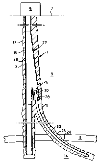
Referring to Fig. 1 there is shown a wellbore
system 1 including a main wellbore 3 extending from a
welihead 5 at the earth surface 7 through an overburden
layer 9 and a cap rock layer 11 to a reservoir zone 14
which contains a hydrocarbon fluid. The cap rock layer 11
is relatively tight and prevents migration of the high
pressure hydrocarbon fluid from the reservoir zone 14 to
the overburden layer 9.
The main wellbore 3 is provided with a tubular steel
main casing 16 which is fixed and sealed into the main
wellbore 3 by a layer of cement 17 and which has an open
lower end. A branch wellbore 18 extends from a wellbore
junction 19 located in the overburden layer 9, through
the overburden layer 9 and the cap rock layer 11, into
the reservoir zone 14. The branch wellbore 18 is provided
with a branch casing 20 having an open lower end and
being connected to the main casing 16 by a casing
junction member 22 in a sealing relationship therewith as
described below. The casing junction member 22 is located
at the wellbore junction 19, i.e. in the overburden
layer 9. The branch casing 20 is sealed into the branch
wellbore 18 by a layer of cement 24. Alternatively the
branch casing can be sealed in the branch wellbore by any
suitable means such as by sealing packers.
Referring further to Figs. 2, 2A, 2B and 3, the
casing junction member 22 has a tubular main bore 24
having longitudinal axis 24a, the main bore 24 being
aligned with the main casing 16, and a tubular branch
bore 26 having longitudinal axis 26a. The branch
casing 20 extends into the branch bore 26 with an annular
space 28 therebetween. An annular sealing device 30 is
arranged in the space 28, which sealing device 30 is
movable between a radially retracted mode and a radially
CA 02349188 2001-05-02
WO 00/26501 PCT/EP99/08689
- 6 -
expanded mode. In the retracted mode the sealing device
is radially spaced from the branch bore 26 and from the
branch casing 20 as shown in Fig. 2. In the expanded mode
the sealing device 30 is expanded against the branch bore
26 and the branch casing 20 as shown in Fig. 3.
The casing junction member 22 is a monolithic
structure and has a generally circular transverse
cross-section, as shown in Figs. 2A and 2B. Such
structure and shape provide adequate collapse resistance
to the casing junction member 22, which should not be
less than the collapse resistance of the main casing 16.
In Fig. 4 is shown detail A of Fig. 3. The sealing
device 30 includes a metal annular body 34 having two
sealing rings 36a, 36b and an annular wedge 38 which is
arranged between the sealing rings 36a, 36b and is in
operative relationship therewith so as to radially press
sealing ring 36a against the branch bore 26 and sealing
ring 36b against the branch casing 20 upon axial movement
of the wedge 38 into the annular..body 34. The contact
surfaces between the wedge 38 and the sealing rings 36a,
36 b are serrated so that the wedge becomes locked to the
sealing rings once such inward axial movement has
occurred. A number of circumferentially spaced rods 40
extend through corresponding holes 41 provided in the
wedge 38, each rod having a threaded end 40a connecting
the rod to the annular body 34 and a T-shaped head 40b at
the other end. The rods 40 are made of shape memory metal
and assume an axially extended shape below a selected
transition temperature and an axially retracted shape
above the transition temperature. In the axially extended
shape, the wedge 38 is in an initial position whereby
sealing ring 36a is radially spaced from the surface of
the branch bore 26 and sealing ring 36b is radially
spaced from the outer surface of the branch casing 20. In
the axially retracted shape of the rods 40, the wedge 38
CA 02349188 2001-05-02
WO 00/26501 PCT/EP99/08689
- 7 -
is pulled by the rods between the sealing rings 36a, 36b
whereby sealing ring 36a becomes pressed against the
surface of the branch bore 26 and ring 36b against outer
surface of the branch casing 20 so as to form a metal-to-
metal seal between the branch bore 26 and the branch
casing 20. Annular body 34 is connected to a lock nut 42
by a bearing 44 which allows rotation of the lock nut 42
relative to the body 34 about longitudinal axis 26a. Lock
nut 42 is connected to the branch casing 20 by screw
connection 46.
Fig. 4 furthermore shows a locking and centralising
assembly 48 arranged between the branch bore 26 and the
branch casing 20, the assembly 48 including a self-
expanding lock ring 50 which is supported on a shape
memory metal actuator ririg 52 which in turn is supported
on a tapered landing ring 54. The landing ring 54 rests
against an annular shoulder 55 provided at branch
casing 20 and has an outer annular groove 56 in which a
split actuator ring 58 of shape memory metal is arranged.
The assembly 48 is retained between an annular retaining
ring 60 and an annular shoulder 62 provided at the outer
surface of the branch casing 20. The retaining ring 60
can be shrink fitted, screwed, snap fitted or welded to
the branch casing 20. The actuator ring 52 assumes an
axially retracted shape below a selected transition
temperature and an axially extended shape above the
transition temperature. The split actuator ring 58
assumes a radially retracted shape below the selected
transition temperature and a radially extended shape
above the transition temperature. An annular groove 64 is
provided in the branch bore 26, into which the
assembly 48 fits with some axial and radial clearance if
the actuator rings 52, 58 are below their transition
temperature. If the actuator rings 52, 58 are above their
transition temperature the lock ring 50 is pressed
CA 02349188 2001-05-02
WO 00/26501 PCT/EP99/08689
- 8 -
against shoulder 62 by the axially expanded actuator
ring 52, and the landing ring 54 is centralised in the
branch bore 26 by the radially expanded actuator ring 58.
The transition temperature of the actuator rings 52, 58
is selected slightly below the transition temperature of
the rods 40.
During normal operation of the wellbore system 1, the
main wellbore 3 is drilled and the main casing 16 with
the casing junction member 22 incorporated therein is
lowered and cemented into the main wellbore 3. During the
installation and cementing procedure the branch bore 26
is at the lower end thereof closed by a plug (not shown)
which can be drilled out. A whipstock (not shown) is then
positioned in the main casing 16 and casing junction
member 22 so as to direct a drill string (not shown) into
the branch bore 26. A removable wear bushing (not shown)
is temporarily arranged in the branch bore 26 to prevent
contact of the drill string with the surface of the
branch bore 26. The drill string is then lowered through
the main casing 16 and guided by the whipstock into the
branch bore 26. The drill string is rotated to drill out
the plug and to drill the branch wellbore 18. After
completing the drilling operation the wear bushing is
removed from branch bore 26 and the branch casing 20 is
lowered through the main casing 16 and guided by the
whipstock (or by any other suitable guiding means) into
the branch wellbore 18 until the self-expanding lock ring
50 latches into annular groove 64. The branch casing is
supported by landing ring 54 and shoulder 55.
The sealing device 30 is lowered through the main
casing 16 and guided into branch bore 26 whereby the
annular body 34 enters the annular space 28 until lock
nut 42 arrives at the upper end of the branch casing 20.
The lock nut 42 is then screwed to the branch casing
using a suitable setting tool (not shown) whereby the
CA 02349188 2001-05-02
WO 00/26501 PCT/EP99/08689
- 9 -
bearing 44 allows the annular body 34 to be non-rotating
while the lock nut is rotated. By virtue of the design of
the sealing device 30, the wedge 38 and sealing
rings 36a, 36.b are accurately positioned in the annular
space 28. Reversal of the above procedure using the
setting tool allows the sealing device 30 to be withdrawn
from the annular space 28, for example to install a new
seal.
A heating device (not shown) is lowered through the
main casing 16 and guided into branch bore 26. Heat is
transferred from the heating device to the shape memory
metal elements 52, 58 and 40. Upon reaching their
respective transition temperature actuator ring 52
expands axially and actuator ring 58 expands radially
thereby axially locking and centralising branch casing 20
in branch bore 26. The rods 40 axially retract upon
reaching their respective transition temperature and
thereby pull wedge 38 between the sealing rings 36a, 36b
whereby ring 36a becomes pressed against the surface of
the branch bore 26 and ring 36b against the outer surface
of the branch casing 20 so as to form a metal-to-metal
seal between the branch bore 26 and the branch casing 20.
The wedge 38 becomes locked to the rings 36a, 36b by
virtue of the serrated contact surfaces between the
wedge 38 and the rings 36a, 36b. As the heating device is
turned off and the temperature of the rods 40 drops below
the transition temperature thereof, the rods axially
expand through the respective holes 41 of wedge 38 while
the wedge remains locked to the sealing rings. Cement is
pumped between the branch casing 20 and the branch
borehole 18 to form cement layer 24 which seals the
branch casing in the branch borehole 18.
After completion of wellbore system 1, production of
hydrocarbon fluid, e.g. high pressure natural gas, from
the reservoir zone 14 is commenced. The fluid flows from
CA 02349188 2001-05-02
WO 00/26501 PCT/EP99/08689
- 10 -
the reservoir zone 14 into the main casing 16 and the
branch casing 20 and through these casings to the
wellhead 5 from where the fluid is further transported to
a suitable processing facility (not shown). The metal-to-
metal-seal provided by sealing device 30 prevents leakage
of fluids through annular space 28 to the overburden
layer 9. Cement layers 17 and 24 seal the main casing 16
and the branch casing 20 in their respective wellbores so
that leakage of gas from the reservoir zone 14 along the
casings 16, 20 to the overburden layer 9 also is
prevented. In this manner it is achieved that gas is
produced through the casings 16, 20 without the need for
conventional production tubings, and without the risk of
gas leaking from the reservoir zone 14 to the overburden
layer 9.
Another advantage of the system of the invention is
the option of including a secondary conduit extending
from the wellhead (which is provided with a blow out
preventer) through the main casing and into the branch
bore of the casing junction member in a sealing
relationship with said branch bore. The secondary conduit
can be, for example, a hydrocarbon fluid production
conduit for separate production of hydrocarbon fluid from
the branch wellbore and main wellbore e.g. in case of a
high fluid pressure difference between the main wellbore
and the branch wellbore. Alternatively, the secondary
conduit can be a service liner for guiding a wellbore
tool from the earth surface into the branch wellbore,
such as a drill string for further drilling of the branch
wellbore. An advantage of the application of such service
liner is that fluid production through the main wellbore
is continued while wellbore operations in the branch
wellbore are carried through the service liner which
isolates such operations from the remainder of the main
wellbore and any other branch wellbores thereof. The
CA 02349188 2001-05-02
WO 00/26501 PCT/EP99/08689
- 11 -
secondary conduit is preferably provided with a latching
mechanism which latches into the branch bore.
Optionally the branch casing can be provided in its
upper end part with a flow control valve which is
retrievable to surface by wireline or coiled tubing. The
flow control valve controls the flow of hydrocarbon fluid
through the branch casing and is operated by telemetry or
by a selected property of the fluid under control.
Furthermore, a safety valve can be installed in the
far end part of the branch casing which operates by
telemetry or by a property of the fluid under control,
for example a selected fluid pressure difference across
the safety valve.
The flow control valve and the safety valve each have
a reverse flow bypass which permits the reverse flow of
fluids upon the occurrence of a selected reverse fluid
pressure difference across the valve.
Referring to Fig. 5 there is shown an anchoring
device 68 arranged within a conduit 70 arranged in a
wellbore (not shown) and having longitudinal axis 71. The
anchoring device is radially expandable relative to the
conduit 70 from a retracted mode whereby the device 68 is
radially spaced from the conduit 70, to an expanded mode
whereby the device 68 is radially expanded against the
conduit 70. The anchoring device 68 includes a
cylindrical body 72 which fits longitudinally in the
conduit 70 and radially deformable annular anchors 74, 76
which are arranged at opposite ends of the cylindrical
body 72. A wedge-shaped annular expander ring 78 fits
within anchor 74 and a similar wedge-shaped expander
ring 80 fits within anchor 76. The expander rings 78, 80
are interconnected by a plurality of circumferentially
spaced rods 82 made of shape memory metal. Each rod 82
extends through a corresponding bore 84 provided in
expander 78 and has a T-shaped head 86 at the outer end
CA 02349188 2001-05-02
WO 00/26501 PCT/EP99/08689
- 12 -
of the bore 84, and is connected to expander 80 by a
screw connection 88. The contact surface between the
expander ring 78 and the anchor 74, and the contact
surface between the expander ring 80 and the anchor 76
are serrated so as to lock the expander rings 78, 80 to
the respective anchors 74, 76 upon inward axial movement
of the expander rings 78, 80. The rods 82 are
transformable from an extended shape below a selected
transition temperature to an retracted shape above the
selected temperature. In the extended shape of the rods
82, the expander rings 78, 80 are at an initial axial
distance whereby the anchors 74, 76 are radially spaced
from the inner surface of the conduit 70. Upon trans-
formation of the rods 82 to the retracted shape, the rods
82 axially pull the expander rings 78, 80 towards each
other thereby radially deforming the anchors 74, 76
against the inner surface of the conduit 70 which thereby
become locked against the conduit 70.
During normal operation a heater is lowered in the
cylindrical body 72 and operated so as to raise the
temperature of the rods 82 to the transition temperature
whereupon the rods retract so as to pull the expander
rings 78, 80 towards each other and thereby radially
expand the anchors 74, 76 against the inner surface of
the conduit 70. The expander rings 78, 80 become locked
to the respective anchors 74, 76 by virtue of the
serrated contact surfaces. The rods 82 can expand freely
through bores 84 when the temperature of the rods drops
again below the transition temperature.
Referring to Figs 1-5, instead of the main wellbore
and the branch wellbore producing from a single reservoir
zone, these wellbores can produce from mutually spaced
reservoir zones.
The above detailed description refers to a main
wellbore and one branch wellbore for the sake of
CA 02349188 2001-05-02
WO 00/26501 PCT/EP99/08689
- 13 -
simplicity. It will be clear that the invention can
equally be applied for a plurality of branch wellbores.
Instead of the casing junction member being a
monolithic structure, it can be assembled form separate
parts. Further, the cross-sectional shape of the junction
member can be elliptical or polygonal instead of
circular.
Further, instead of using memory metal elements which
are to be heated to reach the transition temperature,
memory metal elements can be applied which are to be
cooled to reach their respective transition temperatures.
In that case a cooling device is lowered into the
wellbore system instead of a heating device.