Note : Les descriptions sont présentées dans la langue officielle dans laquelle elles ont été soumises.
CA 02349286 2001-05-03
Device for feeding molten plastic extrudates which
emerge from dies to a discharge channel
The invention relates to a device for feeding molten
plastic extrudates which emerge from dies to a
discharge channel having a cooling water inlet which
follows the dies, in which device the dies are arranged
in at least two rows, in such a manner that in the
discharge direction extrudates from one row and the
other row are guided alternately, next to and at a
distance from one another.
A device of this type is known from DE 26 55 840 A1. In
this device, the extrudates from two rows of dies which
lie parallel and next to one another are guided via an
arrangement of discharge channels in which the
extrudates from in each case one row of dies are fed to
an associated discharge channel and the two discharge
channels are arranged back to back with respect to one
another. In order to provide the extrudates with the
necessary guidance, the discharge channels each form an
outwardly directed, rounded projection onto which the
extrudates are pulled. At their lower end, the
discharge channels are brought together, so that the
extrudates come together next to one another in such a
manner that in an intermeshing position, i.e. arranged
alternately next to one another with regard to their
associated row, they are passed onward to a pelletizer
with a relatively short distance between them.
The invention is based on the object of making it
possible to apply the principle of bringing together
extrudates which ultimately lie relatively closely
adjacent to one another in a device in which the
plastic extrudates are guided via a single, sloping
discharge channel.
CA 02349286 2001-05-03
This object is achieved, in conjunction with the
preamble of patent claim 1, in that two collection
channels, which are arranged one above the other, are
interposed between the dies and the discharge channel,
in such a manner that the extrudates emerging from one
row of dies are in each case fed to the discharge
channel as a group via one of the collection channels,
the individual extrudates of the two groups meeting one
another in an intermeshing position alternately and
next to one another on the discharge channel and being
guided onward by the latter.
On each of the two collection channels, the extrudates
as a group are immediately superficially cooled by the
corresponding cooling water inlet, so that after they
leave the collection channels the extrudates can no
longer stick to one another. The device according to
the invention takes advantage of this in that, on
account of the arrangement of the dies, initially on
each collection channel the extrudates are guided as a
group at a distance which prevents them from sticking
to one another. However, since the dies of one row of
dies are arranged offset with respect to the dies
belonging to the other row of dies, the extrudates
which are supplied from each collection channel and are
relatively well spaced apart from one another come
together on the discharge channel, with the distance
between them which was previously maintained on the
respective collection channel being reduced by half;
however, on account of the cooling of their surfaces
which has taken place in the meantime, this does not
cause any problems and the extrudates are reliably
prevented from sticking to one another on the discharge
channel. However, the discharge channel can now carry
twice the number of extrudates closely adjacent to. one
another compared to each collection channel, i.e. given
the same width of discharge channel compared to the
CA 02349286 2001-05-03
- 3 -
known device it is now possible for the discharge
channel to guide twice the number of extrudates next to
one another, with the result that the throughput of the
device according to the invention with only one
discharge channel is doubled compared to the known
discharge channel arrangement, without the discharge
. channel having to be widened. This of course has an
equally beneficial effect on the pelletizer, which is
likewise able to process twice the number of extrudates
without its width having to be increased.
To prevent further processing of extruded material
which has been supplied from the dies and has not yet
reached the required quality for further processing,
the device is expediently configured in such a way that
each collection channel is arranged so that it can be
displaced between an operating position, in which the
extrudates are collected by a collection channel and a
start-up position, in which the extrudates are guided
adjacently past the collection channel in question.
Only when extruded material which is of a suitable
quality for processing is supplied is this material,
following displacement of the collection channels into
the operating position, collected and supplied to the
dicharge channel for further processing.
The separation between extruded material which can be
processed and extruded material which cannot be
processed is facilitated by the fact that at least one
collection channel is assigned a separating element
which, when displaced through the drop line of the
extrudates into the operating position, takes hold of
the extrudates and then severs them. This type of
separation of extruded material is referred to in
EP 0 086 400 B1. A particular configuration of .the
device with a separating element which covers the dies
advantageously consists in the fact that a separating
CA 02349286 2001-05-03
- 4 -
element which covers the dies is provided above the
uppermost collection channel, which separating element,
during displacement from the operating position into
the start-up position, severs the extrudates and, by
means of a diverter element, guides the extrudates
which continue to emerge away from the collection
channels. The diverter element ensures that the
extrudates made from material of insufficient quality
are reliably diverted away from the device.
Exemplary embodiments of the invention are illustrated
in the figures, in which:
Fig. 1 shows an outline illustration of a side view of
the device;
Fig. 2 shows a plan view of the two collection
channels in their operating position, each
collection channel being fed from two rows of
dies;
Fig. 3 shows an illustration which corresponds to that
shown in Fig. 2, but with in each case one
collection channel being fed by one row of
dies;
Fig. 4 shows the device shown in Fig. 1 with the two
collection channels in the start-up position,
in which the extrudates drop freely next to the
collection channels;
Fig. 5 shows a device with a separating element for
separating off and removing the extrudates
emerging from the dies, laterally past the
- 35 collection channels;
CA 02349286 2001-05-03
- 5 -
Fig. 6 shows the device in accordance with Fig. 5 with
an extended separating element (operating
position), the extrudates entering the
collection channels;
Fig. 7 shows the arrangement in accordance with Fig. 1
with a separating element which has been pushed
under the extrudates and with the extrudates
being diverted away (start-up position).
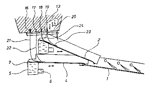
Fig. 1 shows the die block 13 with the four rows of
dies 16, 17, 18 and 19, which each have a number of
dies 20, to illustrate which a perspective view in the
region of the die block 13 has been selected. The
arrangement of the dies 20 in the rows of dies 16-17
can also be seen from Fig. 2.
The dies 20 belonging to the rows of dies 16 and 17
deliver the molten extrudates 21 and 22, and the dies
belonging to the rows of dies 18 and 19 deliver the
molten extrudates 23 and 24. The extrudates 21 and 22
are collected by the displaceable collection channel 4,
which is arranged so that it can be displaced to and
fro in the horizontal direction, as indicated by the
double arrow in the drawing. The collection channel 4
opens into the discharge channel 1. The collection
channel also contains the water reservoir 5, to which
cooling water is supplied via the inlet 6, which
cooling water is fed, through the slot 7 in the water
tank 5, to that part of the collection channel 4 which
collects th.e extrudates 21 and 22. The cooling water
runs over the bottom of the collection channel 4,
entraining the extrudates 21 and 22 toward the
discharge channel 1, during which process it cools the
surfaces of the collected extrudates 21 and 22, so .that
they are transferred to the discharge channel at the
end of the collection channel 4 in a state in which,
CA 02349286 2001-05-03
- 6 -
despite being arranged relatively close together on the
- discharge channel 1, they cannot stick to one anothe r.
On the collection channel 4, the extrudates 21 and 22
run at a distance from one another which is such that
they cannot come into contact with one another.
A similar arrangement applies to the extrudates 23 and
24 on the collection channel 2.
The extrudates 23, 24 and 21, 22 which have been picked
up by the collection channels 2 and 4, which are of
substantially equal length, are passed from the
collection channels to the discharge channel 1, on
which the extrudates are guided onward, together with
the cooling water which has been supplied to the
collection channels 2 and 4, and ultimately passed into
a pelletizer (not shown). With regard to this further
function, in particular the discharge channel 1,
reference is made to EP 0 086 400 B1.
The arrangement of the dies 20 in the rows of dies 16,
17, 18 and 19 results in the extrudates being guided in
such a way that, as explained in more detail below, it
is ensured that the extrudates are guided particularly
close together on the discharge channel 1. This will be
explained with reference to Fig. 2.
Fig. 2 diagrammatically depicts the arrangement of the
rows of dies 16, 17 and 18, 19 together with the dies
20, the rows of dies 16 and 17 passing the extrudates
21 and 22 supplied from the dies to the collection
channel 4 as a group, only a section of the collection
channel 4 being illustrated in this figure. The dies 20
belonging to the rows of dies 18 and 19 supply their
extrudates 23 and 24 to the collection channel 2 as a
further group. Since the collection channel 2 is
situated above the collection channel 4 (cf. Fig. l),
CA 02349286 2001-05-03
- 7 -
the extrudates 21 and 22, as they are passed onward,
initially disappear beneath the collection channel 2
until they reappear below the collection channel 2,
where they meet the extrudates 23 and 24 as they pass
onto the discharge channel 1. As is clearly shown in
Fig. 2, the individual dies 20 are arranged in such a
way that the extrudates running on a collection channel
2 or 4 initially maintain a distance which is such that
. they do not touch one another and therefore also cannot
stick to one another. Only when all the extrudates come
together on the discharge channel 1 does the
interleaved arrangement of the dies 20 in the
individual rows of dies 16-19 lead to a uniform closely
packed arrangement in which the extrudates could come
into contact with another under certain circumstances,
although this can no longer lead to the extrudates
sticking together, since the extrudates have been
sufficiently cooled on their surfaces on account of
being guided over the upstream collection channels 2
and 9. The result is a particularly closely packed
guidance of extrudates on the discharge channel 1. The
discharge channel 1 and therefore also a downstream
pelletizer can therefore be optimally utilized for
extrudate guidance and pelletizing of the extrudates
with regard to the width available.
Fig. 3 shows a variant on the arrangement of dies
illustrated in Fig. 2. In accordance with Fig. 3, there
are only two rows of dies 20, namely the two rows 14
and 15, which in a similar manner to the arrangement
shown in Fig. 2 supply the extrudates which they have
delivered, as a group, on the associated collection
channel 2 or 4, respectively, at a sufficient distance
from one another. After the extrudates have been
brought together on the discharge channel 1, the
closely packed extrudate guidance which has already
been shown in Fig. 2 then results, leading to the same
CA 02349286 2001-05-03 y~~~~~"'~'
result as the extrudate guidance shown in Fig. 2. Of
course, the arrangement of the dies shown in Fig. 3 can
also readily be employed in a device as shown in
Fig. 1.
A particular feature of the device according to the
. invention, which consists in the fact that the
collection channels 2 and 4 can be displaced in the
horizontal direction as indicated by the corresponding
double arrow at the collection channels 2 and 4, will
now be explained on the basis of Fig. 4 and referring
back to Fig. 1. The collection devices 2 and 4 can each
be displaced from an operating position into a start-up
position and vice versa. In the operating position, as
illustrated in Fig. 1, the collection channels 4 and 2
collect the respectively associated extrudates from the
rows of dies 16, 17 and 18, 19 and, in the manner
described above, pass them to the discharge channel 1.
Now, in order to initially keep molten plastic material
which, as is customary, initially does not yet have the
properties required for subsequent further processing,
away from the device when starting up a device of this
tYPe. the possibility of displacement indicated by the
double arrows is provided. In this context, reference
is made to EP 0 086 400 B1, in which the utilization of
a possibility of displacement of this nature is dealt
with in particular detail in connection with a single
discharge channel and in which the components required
for producing the possibility of displacement are
shown. Starting from the operating position illustrated
in Fig. 1, the two collection channels 2 and 4 can be
displaced into the start-up position which is
illustrated in Fig. 4 and in which the extrudates
emerging from the dies 20 drop down freely next to the
collection channels 2 and 4 and therefore cannot pass
into the discharge channel 1. This extruded material
which therefore drops down without being processed,
_. ~.. ....,~,.5~:1~.JW."yi..
CA 02349286 2001-05-03
- - 9 -
during the abovementioned start-up of the device,
represents the initially unusable material which can
then be disposed of in a manner which is of no interest
in this context. When, after a known start-up time, the
extruded material emerging from the dies 20 has reached
the property required for further processing, the two
collection channel's 2 and 4 in this example are
simultaneously displaced into the operating position
illustrated in Fig. 1, the separating elements 3 and 27
which are connected to the collection channel 2 sliding
over the dies 20 and thus severing the emerging
extrudates. The severed extrudates drop down and are
collected separately until the collection channel 2 has
reached its final operating position as shown in
Fig. 1, in which then all the extrudates are collected
by the associated collection channels 2 and 4 and are
passed onward.
The arrangement illustrated in Fig. 4 may also operate
in such a way that the two separating elements 3 and 27
are arranged in such a manner that they can be
displaced separately from one another. It is thus
possible, after severing of the extrudates of extrudate
rows 18 and 19 which have emerged from the dies 20,
initially to move the collection channel 2 into the
operating position. Then, after the extrudates of
extrudate rows 16 and 17 emerging from the dies 20 have
been severed, the collection channel 4 is moved into
the operating position. This start-up variant has the
advantage that the downstream pelletizer (not shown
here) is not immediately operated at full load. The
shut-down process takes place in a corresponding,
reverse order.
The separating elements 3 and 27 are in this case a
type of blade which passes over the planar surface of
the die block 13. The blades 3 and 27 are attached to
CA 02349286 2001-05-03
-
the end of the lever 9 which can rotate about the
pin 8. At its ends which are remote from the blades 3
and 27, the lever 9 is pressed by the tension spring
10, which is attached to the collection channel 2,
5 against the surface of the die block 13, thus ensuring
smooth severing of the strands as soon as they emerge
from the dies 20.
A particular way of diverting away extruded material in
10 the start-up position is illustrated in Figs. 5 to 7.
In accordance with Fig. 5, the device has the diverter
element 11, which comprises an inclined plate which can
optionally be pushed under the dies 20. In Fig. 5, the
diverter element 11 is illustrated in the position in
which it collects and laterally diverts away the
extrudates emerging from the dies 20. So that the
extrudates do not stick to the diverter element, this
element is provided, in a similar manner to the
collection channels, with a water overflow 12, from
which cooling water is guided over the diverter element
11. To allow the water to be discharged without
problems, a suction device 25 is provided at the end of
the diverter element 11, which device, in a known way,
takes up and guides away the water flowing off the
diverter element. When usable extruded material then
emerges from the die block 13, the diverter element is
pushed away, so that the extrudates can then be passed
onto the collection channels, as explained above.
The diverter element 11 is shown in its operating
position in Figure 6. It has been pushed laterally out
of the device and, by means of its blade 26 which
serves as separating element, is pressing against the
surface of the die block 13. To move into the start-up
position, the diverter element 11 is pushed over. the
dies 20, transversely with respect to the extrudates,
so that the emerging extrudates are severed and the
CA 02349286 2001-05-03 ' "
11 -
extrudates which continue to emerge are then collected
by the diverter element.
This is illustrated in Fig. 7. In accordance with
Fig. 7, the diverter element 11 is in the start-up
position, in which the extrudates emerging from the
dies 20 are guided away by the diverter element 11
sufficiently far for the extrudates to be able to be
_ guided past the collection channels 2 and 4. During the
subsequent transfer into the operating position, the
blade 26 then slides past the surface of the die block
13 and therefore the dies 20, with the emerging
extrudates being cut off, so that the extrudates of
usable material which then follow can drop onto the two
collection channels and can thus be passed onward for
further processing.