Note : Les descriptions sont présentées dans la langue officielle dans laquelle elles ont été soumises.
I
CA 02349632 2002-09-12
Musical Instrument Stand
The invention relates to a musical instrument stand for a musical
instrument that has a body and a neck, in particular for guitars or
bass guitars, whereby the.stand has a frame-like structure and two
extended support elements arranged thereon which run parallel to
one another and serve as a support base for the body of the musical
instrument, furthermore comprising an abutment element with a
contact surface arranged on the frame-like structure against which
the neck of the musical instrument is placed.
Musical instrument stands, in particular guitars or bass guitar
stands, having the aforementioned features can already be obtained
on the market. In the known stands, the parallel support elements
for the body usually extend at a right angle to the effective
contact surface of the abutment element for the neck. A guitar
stand of this type is impractical in many situations. It is just
multiple stands of this type that require a large-scale structural
expenditure and much space for storing a plurality of musical
instruments. In the conventional models, the -process of placing
the musical instrument on the stand also requires aiming accuracy
and concentration, however, this can not always be summoned up for
this activity, especially in a hectic stage environment.
An object of the present invention is to provide an alternative
i
CA 02349632 2002-09-12
2
guitar stand which can be easily manufactured from a structural point of
view and which has substantial advantages with respect to handling.
According to this invention a stand for musical instruments which have
a body and a neck comprises a frame-like pedestal, and two elongate
support elements provided on the pedestal which extend parallel to
each other in a spaced relationship to one another and are dimensioned
such that a number of instruments can be placed thereon. The elongate
support elements form a base for supporting the body of a musical
instrument in a position in which a main plane of the musical
instrument extends transversely to a longitudinal extent of the
support elements. An abutment element, arranged on the pedestal,
supports the neck of the musical instrument, and has a neck-supporting
surface which extends generally parallel to the support elements. The
pedestal includes a support frame and the abutment element engages
that support frame, and the stand includes one of foot elements and
wall attachment devices provided on the support frame.
The extended support elements are dimensioned in such a way that a
number of musical instruments can be placed, spaced one from another
along the elongate support elements. The elongate support elements
can comprise an inner support element facing the abutment element, and
an outer support element facing away from the abutment element, the
abutment element lying on a projection of the plane of the support
elements outside of the two elongate support elements.
The elongate support elements can be connected to one another at the end
via side sections. One or more extended abutment elements can be aligned
parallel to the elongate support elements, and each define an abutment for
an instrument. The elongate support elements can be spaced from one
another by 8 to 40 mm, preferably by about 20 to 30 cm. Hinged devices
can be arranged on the frame-like pedestal or in the area of the elongate
support elements; the hinged devices enabling at least the outer support
element to be turned vis-a-vis the abutment element on a swivel axis
parallel to the support elements.
Partitioning devices, which divide the abutment element into several
subsections, can provide for a number of musical instruments arranged
on the abutment element. The support frame can extend at an incline to
i
i i
CA 02349632 2002-09-12
2a
the vertical in a setup position; the extended abutment element or
elements on the one hand, and the foot elements or wall fastening
devices on the other hand, engaging the support frame. The frame-like
pedestal (or structure) and/or the elongate support elements and/or the
extended abutment element can be formed from pipes which are generally
circular in cross section. The elongate support elements and/or the
extended abutment element can be provided at least partially with a
plastic cover made of foamed material with a comparatively high
coefficient of static friction. The two elongate support elements can
reinforce the frame-like structure as bracing.
With the present invention the abutment element for the neck of the
musical instrument extends with its effective contact surface
essentially parallel to the two elongate (or extended) support
elements for the body of the musical instrument. A guitar or bass
guitar is thereby positioned on the spaced support elements in such a
way that its preferential plane extends both at a right angle to the
support elements and also at a right angle to the provided contact
surface or contact line of the abutment element. In the stand
according to the invention, the guitar is placed on the stand or
removed from the stand essentially in direction of its preferential
plane. In this case, a rotary movement takes place simultaneously
about an axis at a right angle to the preferential plane of the
guitar. On the other hand, in conventional guitar stands, the guitar
is turned about an axis extending in the preferential plane of the
guitar.
In a preferred embodiment, a novel multiple stand is created with the
invention. In this case, the elongate (extended) support elements
are dimensioned in such a way that a plurality of musical instruments
can be placed at a distance from one another along the extended
support elements. Especially in the case of a guitar or a bass
guitar, the instruments are thus placed in rows behind one another
which represents an especially space-saving and simultaneously
aesthetically appealing storage possibility. According to a special
aspect of the present invention, the extended support
CA 02349632 2001-06-04
3
elements are configured continuous, so that a support element
supports, at least partially, several guitars. However, the
support elements can also be divided into several sections, as long
as a number of musical instruments can be placed in rows or
slightly staggered.
According to an especially preferred aspect of the present
invention, the contact surface or contact line lies in a projection
on the plane of the support elements outside of the two extended
support elements. If the stand is placed in such a way that the
plane of the support elements runs essentially horizontal, then the
aforementioned arrangement ensures that the musical instruments
rest against the abutment element at a specific incline to the
vertical and that, due to the force of gravity, a stable position
is thus assured. Moreover, especially in the case of guitars or
bass guitars, an especially aesthetic effect is obtained with this
inclined positioning.
In a further preferred embodiment, the extended support elements
are connected to one another at the ends via side sections. This
results in a closed form for the support elements extending
parallel to one another. The side sections offer a certain lateral
protection of the stand and protect the instruments stored on it.
According to a further aspect of the present invention, the support
elements are spaced from one another in such a way that the musical
instruments do not merely lie on the support elements from the top
but sink somewhat into the area between the support elements, so
that the musical instrument is further stabilized by this. The
distance between the extended support elements is between 8 and 40
cm, preferably between about 20 and 30 cm, when used for guitars or
bass guitars.
CA 02349632 2001-06-04
4
In a further advantageous emodiment, hinged devices are arranged on
the frame-like structure or in the area of the extended support
elements, said hinged devices enabling at least the outer support
element to turn vis-a-vis the abutment element about a swivel axis
that is essentially parallel to the support elements. As a result,
the required size can be reduced for transport. At the same time,
there is a saving in manufacturing costs and storage costs at the
marketing end.
In a practical embodiment, several partitioning devices which
divide the extended support element provided for a plurality of
musical instruments into several subsections are arranged on the
abutment element. As a result, it is substantially clearer for the
user to see a spacing of the musical instruments.
In a practical embodiment, the frame-like structure comprises a
support frame that extends inclined to the vertical when set up and
which, on the one hand, acts upon the abutment element or elements
and, on the other hand, foot elements or wall fastening devices.
The stand for musical instruments is in principle intended as a
stand to be placed on a floor surface. However, with
modifications, it is also suitable for wall fastening, in which
case care must be taken in certain circumstances that it is spaced
from the wall for guitars or bass guitars.
In an especially advantageous, stable and yet easy to manufacture
embodiment, the frame-like structure and/or the extended support
elements and/or the abutment element are formed by pipes which are
circular in cross section.
To protect the musical instruments and/or to better secure the
musical instruments against side slipping, the extended support
elements and/or the abutment element are provided at least
CA 02349632 2001-06-04
partially with plastic covers made of a foamed material with a
comparably high coefficient of static friction. Moreover, side
slipping can also be limited or prevented by appropriately
configured partitioning devices.
Furthermore, an independent aspect of the present invention can be
seen therein that the two support elements reinforce the frame-like
structure as braces. The support elements thus fulfil a double
function. On the one hand, they serve as support for the body of
the musical instrument. On the other hand, they reinforce the
frame-like structure of the stand.
The invention will be described in greater detail in the following,
also with respect to further features and advantages, with
reference to the description of embodiments and with reference to
the attached drawings, showing:
Fig. 1 An embodiment of the musical instrument stand with a bass
guitar accommodated therein, in a first side view.
Fig. 2 the stand of Fig. 1 in a view from the top, without bass
guitar.
Fig. 3 a sectional view through the stand of Fig. 1 along the
line III-III.
Fig. 4 a front view of the stand of Fig. 1.
Fig. 5 the stand of Fig. 1 in a folded position.
Fig. 6 a first alternative embodiment of the musical instrument
stand of Fig. 1.
I ~i i
CA 02349632 2002-09-12
6
Fig. 7 a second alternative embodiment of the musical instrument
stand of Fig. 1.
Fig. 8 a third alternative embodiment of the musical instrument
stand of Fig. 1.
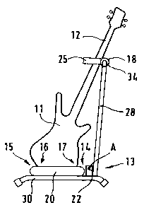
An embodiment of the musical instrument stand is shown in a first
side view in.Fig. 1, a bass guitar having been inserted into the
musical instrument stand for illustration. The stand according to
Fig. 1 comprises a frame-like structure 13 which comprises foot
elements 29, 30 and a support frame 28 essentially configured U-
shaped here. The U-shaped support frame 28 is connected with the
foot elements 29, 30 via hinged devices 21, 22 in each case.
Two extended support elements 14, 15 running parallel to one
another are connected via side sections 19, 20 to form a
rectangular ring 36 provided with rounded corners. The ring 36 is
preferably secured via a screw connection to the foot elements 29,
30 in the area of its side sections 19, 20, so that the stability
of the frame-like structure 13 is increased by the extended support
elements 14, 15. This aspect that the extended support elements
serve a double function, namely the bracing of the musical
instruments to be stored on the one hand and as a brace for the
frame-structure 13 on the other hand, is claimed as an independent
aspect of the invention.
To protect the musical instrument to be stored and to increase the
static friction against side slipping, the ring 36 is covered with
a foamed plastic material "SuperlonnTM
One or more bass guitars consisting of a body 11 and a neck 12 each
can be inserted into the ring 36 with their preferential plane at
a right angle to the extended support elements 14, 15, as shown in
CA 02349632 2001-06-04
7
Fig. 1. The body 11 of the guitar or bass guitar is placed on the
extended support elements 14, 15 at support points 16, 17 that can
be freely selected in the present embodiment. The guitar or bass
guitar is thereby inserted and removed essentially in a direction
which is in the preferential plane of the guitar, if necessary,
while simultaneously turning the guitar or bass guitar about an
axis of rotation that is at a right angle to its preferential
plane.
In the present embodiment, in the area of the support frame facing
away from the foot elements 29, 30, an abutment element 13 also
extended in this case is formed on the centre leg of the U-shaped
support frame, said abutment element extending parallel to the
extended support elements 14, 15 and defining a contact surface or
contact line as upper abutment for the musical instrument to be
stored. In the present embodiment, a guitar or bass guitar is
leaned again the abutment element 18 in the area of its neck.
On the extended abutment element 18, partitioning devices 23, 24,
25 can also be provided which here extend essentially at a right
angle to the abutment element 18 and, in the case of a mutliple
stand, define partitions for the plurality of musical instruments.
At the same time, the partitioning devices can also, as in the
present embodiment, serve as further lateral stabilization, in this
case, as a further contact possibility for the guitar or bass
guitar.
The stand of Fig. 1 is shown in a view from the top in Fig. 2. The
extremely characteristic ring 36 which consists of the extended
support elements 14, 15 and the side sections 19, 20 can be clearly
seen here as a common support base for a number of musical
instruments. At the same time, the ring 36 serves as a bracing
element for the frame-like structure 13. The design of the
CA 02349632 2001-06-04
8
extended abutment element 18 having the partitioning device 23, 24,
25 for a plurality of guitars, already described above, can also be
seen more clearly in Fig. 2. Subsections 26, 27, provided for
inserting a musical instrument each, are formed between each of the
partitioning devices 23, 24, 25. Depending on the design of the
musical instrument, if need be, it is also possible for several
musical instruments to be inserted in a subsection 26, 27.
However, this increases the danger of mutual damage when inserting
or removing the musical instrument from the stand.
The abutment element 18 and the partitioning devices 23, 24, 25
extending at a right angle here to the extended abutment element 18
form lateral boundaries for the respective subsections 26, 27 and
prevent a stored guitar from tipping over parallel to the support
elements. The partitioning devices 23, 24, 25 are provided with
plastic covers 34 to increase the static friction and to protect
the musical instruments.
A sectional view of the stand of Fig. 1 is shown in Fig. 3, wherein
the ring 36 and the frame-like structure are first formed from
pipes, preferably metal pipes. The already mentioned plastic cover
33 is placed on the metal pipe of the ring 36. The centre leg of
the support frame 28, U-shaped in this case and covered by a
plastic cover 34, extends on the inside in the area of the abutment
element 18.
As already noted, hinged devices 21, 22 are provided to turn the
support frame 28 vis-a-vis the foot elements 29, 30 with the ring
36 fastened thereto. In this case, the hinged devices comprise a
flange with a bore arranged on the foot elements 29, 30.
Furthermore, a flange each is allocated to the distal ends of the
here U-shaped support frame 28 and provided with a corresponding
bore. The bores of the four flanges are aligned to one another and
CA 02349632 2001-06-04
9
are each articulated in pairs via a screw bolt. The aligned bores
or screw bolts define a swivel axis A about which the support frame
28 can be turned relative to the foot elements 29, 30.
For the sake of illustration, the stand of Fig. 1 is again shown in
a front view in Fig. 4 in which the U-shaped design of the support
frame 28 can be clearly seen.
The stand is shown in a folded position in Fig. 5. In this case,
the ring 36 simultaneously serves as a support base for the support
frame 28. In the unfolded position, the distal ends of the here U-
shaped support frame 28 form an abutment which is situated on the
foot elements 29, 30. The geometry between the distal ends of the
support frame 28 and the foot elements 29, 30 is thereby
dimensioned in such a way that the outer leg of the support frame
28 has an angle vis-a-vis the plane of the ring 36 of more than 90°,
preferably from 91 to 96°, in the unfolded position.
In Fig. 6, an alternative embodiment is shown which illustrates a
wall fastening of the stand. For this purpose, for example, wall
fastening elements 31, 32 that enable a fastening to a wall can
engage in the support frame 28. However, a sufficient distance
from the wall must be attained, so that the stands with the wall
fastening devices 31, 32 shown here can be fastened preferably to
the front sides of a shelf unit or the like.
A second alternative embodiment is shown in Fig. 7. As already
mentioned above, the basic idea of the invention also includes that
the extended support elements 14, 15 deviate somewhat from an exact
parallel run, as can be seen here e.g. by indentations 35 facing
outward in each case. As a result of the indentations 35 provided
in the ring 36, each facing outward, a guitar or bass guitar can be
secured even better to the given positions in each case, so that an
CA 02349632 2001-06-04
inadvertent change in the relative position of the plurality of
guitars is prevented by the indentations 35.
Furthermore, as can be seen in Fig. 8, it is not a prerequisited
for the invention that the extended support elements 14, 15 extend
in a straight line, parallel to one another. Rather, the novel
idea can also be realized if the support elements have a curved
slope corresponding to one another, such as e.g. a circular slope.
The stand shown in Fig. 8 is suitable for placing in a corner of a
room due to its quadrant-like design. A further obvious embodiment
would be the design of the stand shown in Fig. 8 in a full circle
arrangement, in which case either a number of adjoining rings 36 or
a completely surrounding structure with closed, extended support
elements 14, 15 without side sections 19, 20 could be provided.
CA 02349632 2001-06-04
11
List of Reference Numbers
11 Body
12 Neck
13 Frame-like structure
14,15 Extended support element
16,17 Contact positions
18 Abutment element
19,20 Side sections
21,22 Hinged devices
23,24, 25 Partitioning devices
26,27 Subsections
28 Support frame
29,30 Foot elements
31,32 Wall fastening devices
33,34 Plastic covers
35 Indentations
36 Ring
A Swivel axis