Sélection de la langue

Search

Sommaire du brevet 2351126 

Énoncé de désistement de responsabilité concernant l'information provenant de tiers

Une partie des informations de ce site Web a été fournie par des sources externes. Le gouvernement du Canada n'assume aucune responsabilité concernant la précision, l'actualité ou la fiabilité des informations fournies par les sources externes. Les utilisateurs qui désirent employer cette information devraient consulter directement la source des informations. Le contenu fourni par les sources externes n'est pas assujetti aux exigences sur les langues officielles, la protection des renseignements personnels et l'accessibilité.

Disponibilité de l'Abrégé et des Revendications

L'apparition de différences dans le texte et l'image des Revendications et de l'Abrégé dépend du moment auquel le document est publié. Les textes des Revendications et de l'Abrégé sont affichés :

  • lorsque la demande peut être examinée par le public;
  • lorsque le brevet est émis (délivrance).
(12) Demande de brevet: (11) CA 2351126
(54) Titre français: BOITE A VAPEUR POUR UTILISATION AVEC PRESSES VERTICALES ET HORIZONTALES ET METHODE D'UTILISATION CONNEXE
(54) Titre anglais: STEAM CHEST FOR USE WITH VERTICAL AND HORIZONTAL PRESSES AND METHOD OF USE THEREOF
Statut: Réputée abandonnée et au-delà du délai pour le rétablissement - en attente de la réponse à l’avis de communication rejetée
Données bibliographiques
Abrégés

Abrégé anglais


A steam chest can be used with both a vertical press and a
horizontal press to manufacture foam prototypes in molding plates. The
steam chest has a frame that can accept tooling that has been manufactured
on a horizontal press or a vertical press. The same steam chest can be used
to produce foam prototypes of various shapes and sizes within a particular
size range. When the steam chest is used in a vertical press, the drainage
hole that extends downward is in an edge wall. When the steam chest is
used in a horizontal press, the drainage hole that extends downward is in a
side wall.

Revendications

Note : Les revendications sont présentées dans la langue officielle dans laquelle elles ont été soumises.


The embodiments of the invention in which an exclusive property or
privilege is clamed are defined as follows:
1. A steam chest for use with both a vertical press and a horizontal
press, said steam chest comprising two shells, each shell having an opening
along one side thereof with a flange surrounding said opening, there being
two flanges, one for each shell, a cavity frame having a periphery that is
sized and shaped to correspond to said flanges, said frame being
sandwiched between said flanges when said chest is assembled, said shells
defining a cavity therein, each shell having one side wall and at least one
edge wall extending normal to said side wall, there being two side walls
and at least two edge walls, at least one side wall and one edge wall having
drainage holes therein, said drainage holes having removable plugs so that
the drainage holes in the side wall can be plugged and the drainage holes in
the edge wall can be unplugged when the chest is used within a horizontal
press and vice versa when the chest is used in a vertical press.
2. A steam chest as claimed in Claim 1 wherein the two shells are
identical to one another.
3. A steam chest as claimed in Claim 1 wherein the steam chest has fill
gun openings that permit a fill gun to contact a mold plate, a steam inlet
and outlet and a cooling water inlet and outlet, said chest being insulated.
4. A steam chest as claimed in Claim 1 wherein the frame has a
section therein for receiving a mold plate.
5. A steam chest as claimed in Claim 4 wherein the frame has multiple
sections therein for receiving multiple mold plates, there being one mold
plate for each section.
6. A method of using tooling manufactured on a vertical press on a
horizontal press or vice versa causing a steam chest having two shells, each
shell having one side wall with at least one edge wall extending from a
periphery thereof, each shell having an opening along one side thereof with
a flange surrounding said opening, there being two flanges, one for each
shell, at least one shell having an edge wall with a drainage hole therein and
7

a side wall with a drainage hole therein, said shells being sized and shaped
to receive a frame in which said tooling from said vertical press can be
mounted, said method comprising mounting said tooling in said frame
plate, mounting said frame on said flange of one of said shells, mounting
each shell of said steam chest in a horizontal press with the side wall
containing said drainage hole extending downward or in a vertical press
with the edge wall containing said drainage hole extending downward,
operating said press to close said steam chest with said frame sandwiched
between said flanges.
7. A method as claimed in Claim 6 including the steps of installing a
mold plate into the frame, filling the mold plate with expandable foam
beads using a fill gun or fill guns, circulating steam through the steam chest
to cause the foam beads to expand and gel together, subsequently
circulating cooling water through the steam chest, removing the steam chest
from the press and removing the mold plate from the steam chest.
8. A method of using a steam chest in both a vertical press and a
horizontal press using a steam chest having two shells, each shell having an
opening along one side thereof with a flange surrounding said opening,
there being two flanges, one for each shell, a frame having a periphery that
is sized and shaped to correspond to said flanges, said frame being
sandwiched between said flanges when the chest is assembled with the
shells defining a cavity therein, each shell having one side wall and at least
one edge wall extending normal to said side wall, there being two side
walls and at least two edge walls, at least one side wall and one edge wall
having drainage holes therein with removable plugs, said method
comprising mounting tooling within said frame, mounting said frame
between the flanges of said two shells, mounting the steam chest in a
vertical press with an edge wall containing the drainage hole extending
downward or mounting said steam chest in a horizontal press with the side
wall containing the drainage hole extending downward, operating the press
to open or close the steam chest.
8

9. A method as claimed in Claim 8 including the steps of mounting a
mold plate within said frame, filling the mold plate with foam beams using
a fill gun or fill guns, circulating steam through the steam chest to expand
the beads and cause them to gel, subsequently circulating cooling water
through the steam chest.
10. A method as claimed in Claim 9 including the steps of inserting a
frame with two sections into one shell of the steam chest, each section
containing a mold plate, and filling each mold plate with foam beads using
fill guns.
11. A method of manufacturing foam prototypes of various shapes and
sizes using the same steam chest said steam chest having two shells that
together enclose a cavity, said chest being able to accept tooling of various
shapes and sizes within a specified range, said method comprising choosing
a frame having a section or sections mounting the tooling in a section of
said frame, said frame being sized to fit within the steam chest, installing
the frame against a flange of one shell of the steam chest, mounting the
steam chest in a horizontal or vertical press so that the operation of the
press opens and closes the steam chest with the frame in between said two
shells, filling the tooling with foam beads, heating the tooling by
introducing steam into the steam chest to expand and fuse the beads,
subsequently cooling the steam chest, retrieving the foam prototype formed
in the tooling, repeating the method for tooling of a different size and shape
by choosing a different frame while using the steam chest.
9

Description

Note : Les descriptions sont présentées dans la langue officielle dans laquelle elles ont été soumises.

CA 02351126 2001-06-20
STEAM CHEST FOR USE WITH VERTI AL AND HORIZONTAL
PRESSES AND METHOD OF USE THE FOF
This invention relates to a steam chest and a method of use thereof.
More particularly, this invention relates to a steam chest into which tooling
5 manufactured on a horizontal press can be placed on a vertical press.
Previously, when manufacturing prototype foams of various sizes or
shapes corresponding to particular parts, if the part to be reproduced in a
prototype foam was manufactured on a particular type of press, the
prototype foam had to be manufactured on the same type of press. For
1o example, when a tool was manufactured on a Styrologic vertical press, the
prototype foam also had to be manufactured on a Styrologic vertical press.
Similarly, if a tool had been manufactured on a Kurtz horizontal press, the
prototype foam also had to be manufactured on a Kurtz horizontal press.
Also, where tools varied greatly in size, different size presses would be
15 required to produce the prototype foams. Further, when manufacturing
prototype foams, each size of foam requires a different steam chest, greatly
increasing the time required and greatly increasing the expense.
It is an object of the present invention to provide a device and
method whereby prototype foams can be manufactured on a horizontal
2o press where the original tooling was manufactured on a vertical press or
vice versa. It is a further object of the present invention to accommodate
molds of various shapes and sizes in the same steam chest. It is still a
further object of the present invention to greatly reduce the time input
required to produce prototype foams.
25 A steam chest is used with both a vertical press and a
horizontal press. The steam chest comprises two shells, each shell having
an opening along one side with a flange surrounding the opening. There
are two flanges, one for each shell. A cavity frame has a periphery that is
sized and shaped to correspond to the flanges, the frame being sandwiched
3o between the flanges when the chest is assembled. The shells define a
cavity therein and each shell has one side wall and at least one edge wall

CA 02351126 2001-06-20
extending normal to the side wall. There are two side walls and at least two
edge walls. At least one side wall and one edge wall have drainage holes
therein. The drainage holes have removable plugs so that the drainage
holes in the side wall can be plugged and the drainage holes in the edge
wall can be unplugged when the chest is used within a horizontal press and
vice versa when the chest is used in a vertical press.
A method of using tooling, manufactured on a vertical press,
or a horizontal press or vice versa uses a steam chest having two shells.
Each shell has one side wall with at least one edge wall extending from a
1o periphery thereof. Each shell has an opening along one side thereof with a
flange surrounding the opening. There are two flanges, one for each shell.
At least one shell has an edge wall with a drainage hole therein and one
side wall with a drainage hole therein. The shells are sized and shaped to
receive a frame in which tooling from the horizontal press can be mounted.
15 The method comprises mounting the tooling in the frame, mounting the
frame between the flanges of the shells so that the frame can be sandwiched
between the flanges, rigidly and removably securing the flanges against
either side of the frame by mounting the steam chest in a horizontal press
with the side wall containing the drainage hole extending downward or
2o mounting the steam chest in a vertical press with the edge wall containing
the drainage hole extending downward..
A method of using a steam chest in both a vertical press and
a horizontal press uses a steam chest having two shells. Each shell has an
opening along one side thereof with a flange surrounding the opening.
25 There are two flanges, one for each shell. A frame has a periphery that is
sized and shaped to correspond to the flanges. The frame is sandwiched
between the flanges when the chest is assembled with the shells defining a
cavity therein. Each shell has one side wall and at least one edge wall
extending normal to the side wall. There are two side walls and at least two
3o edge walls. At least one side wall and one edge wall have drainage holes
therein with removable plugs. The method comprises mounting the tooling

CA 02351126 2001-06-20
in an appropriately sized frame for that tooling, mounting the frame
between the flanges of the two shells, mounting the steam chest in a
vertical press with the edge wall containing the drainage hole extending
downward or mounting the steam chest in a horizontal press with the side
wall containing the drainage hole extending downward.
A method of manufacturing foam prototypes of various shapes and
sizes using the same steam chest uses a steam chest having two shells that
together enclose a cavity. The chest is able to accept tooling of various
shapes and sizes within a specified range. The method comprises choosing
1o a frame having a section or sections that are sized to receive the tooling
and
mounting the tooling in a section of the frame. The frame is sized to fit
within the steam chest. The method further comprises installing the frame
against a flange of one shell of the steam chest, mounting the steam chest in
a horizontal or vertical press so that the operation of the press opens and
15 closes the steam chest with the frame in between the two shells, filling
the
tooling with foam beads, heating the tooling by introducing steam into the
steam chest to expand and fuse the beads, subsequently cooling the steam
chest, retrieving the foam prototype formed in the tooling and repeating the
method for tooling of a different size and shape by choosing a different
2o frame while using the same steam chest.
In the drawings:
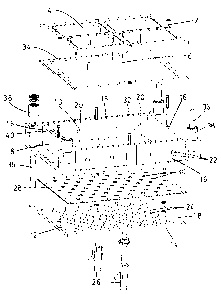
Figure 1 is an exploded perspective view of one half of a steam
chest;
Figure 2 is an exploded perspective view of another half of the
25 steam chest of Figure 1.
Figure 3 is a top view of a single section frame;
Figure 4 is a top view of a dual section frame;
Figure 5 is a top view of a further embodiment of a dual section
frame; and
3o Figure 6 is a top view of a three section frame;

CA 02351126 2001-06-20
In Figures 1 and 2, a frame 2 has four sections 4. The frame 2 is
shown in both Figure 1 and in Figure 2 and provides a point of reference
for each of the Figures. There is only one frame in the steam chest at one
time. The steam chest will preferably have several frames for tooling of
5 different shapes and sizes. Each section 4 is sized to receive one piece of
tooling (not shown). Supports 6 are affixed to the frame to provide support
for the frame. A shell 8 has an opening 10 along one side thereof. The
shell 8 has a cover 12 that forms a side wall 14. Four edge walls 16 extend
normal to a periphery 18 of the cover 12. Two of the edge walls 16 contain
10 two steam/water inlet openings 20 and two steam outlet/drainage holes 22.
The cover 12 contains a plurality of openings 24 to receive fill guns 26. A
plastic liner 28 is located between the cover 12 and the shell 8 and the liner
28 has a plurality of openings 30 which are aligned with the openings 24 of
the cover 12. The openings 24 are covered except for those openings that
t 5 receive a fill gun and except for at least one is left open to provide
drainage
if the steam chest is used in a horizontal press. A flange 32 surrounds the
opening 10 of the shell 8. A gasket 34 corresponds in size and shape to the
flange 32 and lies between the frame 2 and the flange 32. An interior of the
edge walls 16 also contain a layer of plastic (not shown). The liner 28,
2o gasket 34 and the plastic along the inside of the edge walls 16 insulate
the
steam chest. Posts 36 and retainers 38 provide means for aligning the shell
8 shown in Figure 1 to a shell 8 shown in Figure 2 so that the frame 2 is
sandwiched between the flanges 32 of the shells 8. The same reference
numerals are used in Figure 2 to describe those components that are
25 identical to the components of Figure 1. Guide posts 40 assist in aligning
the two shells 8. A cover 42 and corresponding liner 44 shown in Figure 2
do not have openings for the foam guns as the foam can be inserted through
the openings 24 in the cover 12. The cover 42 could be designed to include
openings for the foam guns. The foam guns are designed to be inserted into
3o the openings 24 so that foam beads can pass directly from the barrel of the
guns into the mold plate.
4

CA 02351126 2001-06-20
In Figure 3, there is shown a top view of a frame 50 having a single
section 4. In Figure 4, there is shown a top view of a frame 52 having two
sections 4. In Figure 5, there is shown a top view of a frame 54 with two
sections 4 of a different size than the sections 4 of Figure 4. In Figure 6
5 there is shown a top view of a frame 56 having three sections 4. In
operation, each section contains a mold plate (not shown).
In operation, a mold plate (not shown), containing the mold of the
component for which a foam prototype is desired to be produced, is
installed within a frame. The steam chest of the present invention is
1o designed to receive Styrologic frames, Kurtz frames or frames of other
press manufacturers. The frame and mold plate is then mounted in one of
the shells and the shell is mounted in a press. The other shell is also
mounted in the press and is then aligned with the frame. The press can then
be operated to open or close the steam chest. Assuming that the press is a
t5 Kurtz horizontal press, the steam chest will be placed in the press with
the
cover 12 facing downward. The fill guns would be connected so that foam
beads can be injected into the mold plate or mold plates within the frame.
The foam beads are preferably made from a suitable polymer. The polymer
that is suitable for some tooling is expandable polystyrene. The steam and
2o water connections are also made and the drainage hole on the cover 12
would be unplugged. The press is used to open or close the steam chest
together with the frame sandwiched in between.
As is conventional, after all of the connections have been made, the
foam beads are injected by the fill guns into the mold plate (or plates)
25 within the frame. After the mold plate has been filled with foam beads,
steam is introduced into the steam chest. The steam causes the foam beads
to expand and to fuse together to fill the interior of the mold plate with a
homogeneous foam material. The steam supply is then shut off and, after
insuring that the foam has had time to fuse properly cooling water is
3o introduced into the steam chest to cool the mold plate. The cooling water
flows out of the drainage hole or holes in the cover. After cooling, the
5

CA 02351126 2001-06-20
hydraulic pressure of the press is released and the steam chest can be
opened. The mold plate is removed and opened and the foam prototype is
removed.
From Figures 3 to 6, can be seen that a large mold plate can be used
5 with the frame 50 whereas a small mold plate must be used with the frame
2 shown in Figure 1 as the frame 2 has four sections, but has the same
peripheral size as the frame 50. Thus, a reasonably broad range of sizes of
mold plates can be used by choosing the appropriate size frame from
Figures 1 to 6. The frames can all be used in the same size steam chest.
1o When mold plates exceed the maximum size that can fit within frame 2, a
different size of steam chest will have to be used. Each size of steam chest
will have its own range of single section and mufti-section frames which
will accommodate many different sizes of mold plates. Also, in some uses
of the invention, it may be desirable to leave one or more of the sections of
15 the frame blank when manufacturing a foam prototype. It is not essential
that all of the sections contain a mold plate during operation of the steam
chest. Alternatively, blank plates can be used to fill in those sections of
the
frame for which there is no mold plate.
If desired, adapters can be used to increase the depth of the steam
2o chest to accept unusually large parts or tooling. Since the frames are
interchangeable within a steam chest of a particular size and only the mold
plates vary, a significant time saving is achieved in manufacturing foam
prototypes as the steam chest and frames already exist. As soon as the
mold plate is available, the foam prototype can be manufactured. The same
25 steam chest is used with many different sizes and shapes of mold plates.
6

Dessin représentatif
Une figure unique qui représente un dessin illustrant l'invention.
États administratifs

2024-08-01 : Dans le cadre de la transition vers les Brevets de nouvelle génération (BNG), la base de données sur les brevets canadiens (BDBC) contient désormais un Historique d'événement plus détaillé, qui reproduit le Journal des événements de notre nouvelle solution interne.

Veuillez noter que les événements débutant par « Inactive : » se réfèrent à des événements qui ne sont plus utilisés dans notre nouvelle solution interne.

Pour une meilleure compréhension de l'état de la demande ou brevet qui figure sur cette page, la rubrique Mise en garde , et les descriptions de Brevet , Historique d'événement , Taxes périodiques et Historique des paiements devraient être consultées.

Historique d'événement

Description Date
Inactive : CIB de MCD 2006-03-12
Demande non rétablie avant l'échéance 2005-06-20
Le délai pour l'annulation est expiré 2005-06-20
Réputée abandonnée - omission de répondre à un avis sur les taxes pour le maintien en état 2004-06-21
Modification reçue - modification volontaire 2003-04-25
Modification reçue - modification volontaire 2003-01-27
Demande publiée (accessible au public) 2002-12-20
Inactive : Page couverture publiée 2002-12-19
Lettre envoyée 2002-11-26
Exigences pour une requête d'examen - jugée conforme 2002-10-18
Toutes les exigences pour l'examen - jugée conforme 2002-10-18
Requête d'examen reçue 2002-10-18
Inactive : CIB en 1re position 2001-08-21
Inactive : CCB attribuée 2001-08-21
Inactive : Certificat de dépôt - Sans RE (Anglais) 2001-07-18
Exigences de dépôt - jugé conforme 2001-07-18
Demande reçue - nationale ordinaire 2001-07-18

Historique d'abandonnement

Date d'abandonnement Raison Date de rétablissement
2004-06-21

Taxes périodiques

Le dernier paiement a été reçu le 2003-05-26

Avis : Si le paiement en totalité n'a pas été reçu au plus tard à la date indiquée, une taxe supplémentaire peut être imposée, soit une des taxes suivantes :

  • taxe de rétablissement ;
  • taxe pour paiement en souffrance ; ou
  • taxe additionnelle pour le renversement d'une péremption réputée.

Veuillez vous référer à la page web des taxes sur les brevets de l'OPIC pour voir tous les montants actuels des taxes.

Historique des taxes

Type de taxes Anniversaire Échéance Date payée
Taxe pour le dépôt - petite 2001-06-20
Requête d'examen - petite 2002-10-18
TM (demande, 2e anniv.) - petite 02 2003-06-20 2003-05-26
Titulaires au dossier

Les titulaires actuels et antérieures au dossier sont affichés en ordre alphabétique.

Titulaires actuels au dossier
WILLIAM R. POTTER
Titulaires antérieures au dossier
S.O.
Les propriétaires antérieurs qui ne figurent pas dans la liste des « Propriétaires au dossier » apparaîtront dans d'autres documents au dossier.
Documents

Pour visionner les fichiers sélectionnés, entrer le code reCAPTCHA :


Pour visualiser une image, cliquer sur un lien dans la colonne description du document. Pour télécharger l'image (les images), cliquer l'une ou plusieurs cases à cocher dans la première colonne et ensuite cliquer sur le bouton "Télécharger sélection en format PDF (archive Zip)" ou le bouton "Télécharger sélection (en un fichier PDF fusionné)".

Liste des documents de brevet publiés et non publiés sur la BDBC .

Si vous avez des difficultés à accéder au contenu, veuillez communiquer avec le Centre de services à la clientèle au 1-866-997-1936, ou envoyer un courriel au Centre de service à la clientèle de l'OPIC.


Description du
Document 
Date
(aaaa-mm-jj) 
Nombre de pages   Taille de l'image (Ko) 
Dessin représentatif 2002-03-04 1 17
Page couverture 2002-11-29 1 45
Description 2001-06-20 6 296
Abrégé 2001-06-20 1 16
Revendications 2001-06-20 3 139
Dessins 2001-06-20 6 128
Certificat de dépôt (anglais) 2001-07-18 1 163
Accusé de réception de la requête d'examen 2002-11-26 1 174
Rappel de taxe de maintien due 2003-02-24 1 107
Courtoisie - Lettre d'abandon (taxe de maintien en état) 2004-08-16 1 175
Taxes 2003-05-26 1 32