Sélection de la langue

Search

Sommaire du brevet 2351298 

Énoncé de désistement de responsabilité concernant l'information provenant de tiers

Une partie des informations de ce site Web a été fournie par des sources externes. Le gouvernement du Canada n'assume aucune responsabilité concernant la précision, l'actualité ou la fiabilité des informations fournies par les sources externes. Les utilisateurs qui désirent employer cette information devraient consulter directement la source des informations. Le contenu fourni par les sources externes n'est pas assujetti aux exigences sur les langues officielles, la protection des renseignements personnels et l'accessibilité.

Disponibilité de l'Abrégé et des Revendications

L'apparition de différences dans le texte et l'image des Revendications et de l'Abrégé dépend du moment auquel le document est publié. Les textes des Revendications et de l'Abrégé sont affichés :

  • lorsque la demande peut être examinée par le public;
  • lorsque le brevet est émis (délivrance).
(12) Demande de brevet: (11) CA 2351298
(54) Titre français: PINCE A CABLE DE TRANSMISSION
(54) Titre anglais: COMMUNICATION CABLE CLIP
Statut: Réputée abandonnée et au-delà du délai pour le rétablissement - en attente de la réponse à l’avis de communication rejetée
Données bibliographiques
(51) Classification internationale des brevets (CIB):
  • H02G 03/32 (2006.01)
  • H02G 03/30 (2006.01)
(72) Inventeurs :
  • KAPLAN, STEVE E. (Etats-Unis d'Amérique)
(73) Titulaires :
  • MULTILINK, INC.
(71) Demandeurs :
  • MULTILINK, INC. (Etats-Unis d'Amérique)
(74) Agent: SMART & BIGGAR LP
(74) Co-agent:
(45) Délivré:
(22) Date de dépôt: 2001-06-26
(41) Mise à la disponibilité du public: 2002-03-11
Requête d'examen: 2006-05-19
Licence disponible: S.O.
Cédé au domaine public: S.O.
(25) Langue des documents déposés: Anglais

Traité de coopération en matière de brevets (PCT): Non

(30) Données de priorité de la demande:
Numéro de la demande Pays / territoire Date
09/658,744 (Etats-Unis d'Amérique) 2000-09-11

Abrégés

Abrégé anglais


Communication cable clip has an anchor portion for insertion between
clapboards and a bottom portion which protrudes outwardly to provide
structure having openings for ties for horizontal and vertical runs of cable.

Revendications

Note : Les revendications sont présentées dans la langue officielle dans laquelle elles ont été soumises.


WHAT IS CLAIMED IS:
1. A clip for connecting a generally vertical and/or generally
horizontal run of a communication cable on a wall having overlapping siding
thereon extending in a generally horizontal direction, said clip comprising an
anchor portion at one end dimensioned to slide under an overlapped board of
the overlapping siding to mount said clip on the wall, and a base extending
axially outwardly from said anchor portion, said base providing a support for
a tie portion having vertical and horizontal edge portions extending laterally
outwardly from different sides of said base, said vertical and horizontal edge
portions having cable tie openings for receiving ties for making tie
connections to generally horizontal and vertical cable runs adjacent the
respective horizontal and vertical edge portions.
2. The clip of claim 1 wherein said edge portions containing said
cable tie openings comprise overhangs from respective sides of said base.
3. The clip of claim 1 wherein there are two of said vertical edge
portions extending laterally beyond opposite sides of said base and one said
horizontal edge portion extending laterally beyond another side of said base.
4. The clip of claim 3 wherein said base is dimensioned to maintain
said tie openings in said edge portions in spaced relation frm the overlapping
siding to facilitate running of cable ties through said tie openings.
5. A clip for connecting a generally vertical and/or generally
horizontal run of a communication cable on a wall having overlapping siding
thereon extending in a generally horizontal direction, said clip being
elongated
and comprising a top portion, a bottom portion, and a rear surface for said
portions, said top portion comprising an anchor portion dimensioned to slide
under an overlapped board of the overlapping siding to mount said clip on the
-5-

wall, said bottom portion comprising a tie support structure extending
forwardly from said rear surface below said anchoring portion, and a tie
portion having vertical and horizontal edge portions extending laterally from
different sides of said tie support structure, at least one of said edge
portions
having a cable tie opening for making a tie connection to a generally vertical
axis cable run adjacent the respective edge portion and at least one of said
edge portions having a cable tie opening for making a tie connection to a
generally horizontal axis cable run adjacent the respective edge portion.
6. The clip of claim 5 wherein said edge portions having cable tie
openings for making tie connections comprise overhangs from said support
structure.
-6-

Description

Note : Les descriptions sont présentées dans la langue officielle dans laquelle elles ont été soumises.

CA 02351298 2001-06-26
Attorney Docket MUBRP0103C;A
TITLE: COMMUNICATION CABLE CLIP
The present invention relates to methods of, and a mounting device
for, supporting communication cables, for example, telecommunication, or
CATV, wire or fiber optic cables, in their runs along wall siding thereon, and
particularly to a mounting device capable of simultaneously supporting runs
of a wide range of cable sizes as well as accommodating the removal of a
cable or the addition of a new cable, and of being used to secure cable which
runs either vertically or horizontally along the wall.
Cables have been supported along walls having overlapping siding
using a mounting "clip" which has an anchor portion that slides vertically
under the bottom edge of the overlapping boards of the siding. Such
mounting clips have utilized .an anchor portion which slides vertically under
the bottom edge of the siding boards. Cable have also been tied to
structures by using commercially available plastic self locking ties, the
cable
being encircled by the tie which loops through a device for holding the cable.
Commercial plastic ties are available with a plastic belt length with a self
locking one way "buckle" on one end through which the other end may be
threaded to pull the tie tightly around the cable and lock itself against
releasing.
It is an object of the present invention to provide a siding clip for use
in tying a communication cable to a wall with overlapping siding boards, the
clip being such that it will accommodate the supporting of a wide range of
cable sizes and multiple cables as well as being capable of supporting either
horizontal or vertical runs, and accommodating the addition or removal of
cables being supported by the clip.

CA 02351298 2001-06-26
SUMMARY OF INVENTION
The present invention provides a clip, preferably made of a rigid
plastic, which comprises a satrap, or tie, portion having multiple slots for
receiving ties for supporting cable runs along the side of a building wall,
the
wall having clapboard siding, or other similarly overlapping siding. In
accordance with the invention, a vertical clip, having a vertical rear back
portion extending the vertical length of the clip, comprises a relatively thin
top portion for wedging the clip under the overlap of a siding board or the
like, and a bottom portion which extends over the overlapped siding below
the bottom edge of the overlapping board. The bottom portion of the clip
comprises a support portion for a tie portion having at least one tie opening
for receiving a tie for tying a vertical cable run to the clip and at least a
second opening for similarly tying a horizontal cable run. In the preferred
embodiment the tie portion of the clip has slot openings and is displaced
outwardly from the siding to provide ready access thereto when tying a cable
to the clip. Preferably the openings through the tie support portion of the
clip
for the vertical and horizontal cable runs lie along lines perpendicular to
each
other, with the tie portion being in a plane parallel to the general plane of
the
wall, with the planes for the tie portion and the wall being displaced from
each other to provide easy access to the openings for the ties. In the
preferred embodiment, the tie support portion is preferably an integral part
of
the clip (including both the top and bottom portions) and is preferably of
rectangular shape with oppoaed top and bottom edges and two opposed
vertical sides generally perpendicular to the top and bottom sides, there
being
a tie opening for a horizontal run of cable along the bottom side and at a tie
opening along at least one vE;rtical side, and preferably along both vertical
sides, for tying vertical cable runs.
The clip of the invention may be used to accommodate the use of a
single tie opening to support two cables by using a single tie for each or
using a single tie to encircle the both cables. Thus, a cable slot which
already has a cable tie through it, may be used to tie another cable by
-2-

CA 02351298 2001-06-26
severing the first tie, cutting it if necessary, and using a new tie of
appropriate length to feed through the slot opening and encircle both of the
cables to secure both to the clip.
DESCRIPTION OF DRAWINGS
The following is a description of the drawings of preferred
embodiments of the present invention, forming a part of this specification for
the material disclosed therein, and in which:
Fig. 1 is a view showing cable runs along a wall, each of which are
supported by a clip of the present invention.
Fig. 2 is a front, bottom, right side view looking down on the front of
the cable support clip as the clips are viewed in Fig. 1 .
Fig. 3 is a top plan view of the clip as viewed in Fig. 2.
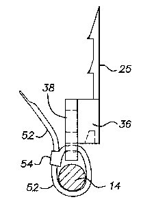
Fig. 4 is a right side view of the clip as shown in Fig. 3.
SPECIFICATION
Referring to Fig. 1, cable clips 10, embodying a preferred embodiment
of the present invention are shown with a clip 10 supporting a horizontal run
of communication cable 14 along a wall 16 while a second clip 10 is shown
as supporting a vertical run of communication cable 18. The wall 16 has
overlapping horizontal clapboard siding with horizontal siding boards 20 each
having a bottom portion 20a, which includes its bottom edge 22, overlapping
the next lower board, all in a conventional manner.
As shown in Figs. 2-4, the clip 10 for securing cable runs preferably
comprises an elongated strip-like plastic structure 24, having a flat back 25
extending the length of the structure, which consists of a top portion 26, or
anchor portion, and a bottom portion 28, the top portion 26 being
dimensioned to be slid endwise underneath the bottom edge 22 of a siding
board to insert the top portion 26 under the overlapping portion 20a of siding
board to wedge the clip, in a conventional manner, between the overlapping
and overlapped boards. The top portion 26 of the clip has an intermediate
-3-

CA 02351298 2001-06-26
thickness 30 to facilitate the movement under the overlapping portion 20a
with the clip having a ramp :32 at the top end of the clip which ramps from
the rear side of the clip to above the intermediate thickness 30. The top
portion 26 of the clip also hays an intermediate ramp 34 which ramps up from
the intermediate thickness 30 between the ramp 32 and the bottom portion
28. The top of the ramps have a tooth like structure 33 to bite into the back
side of the overlapped siding when the clip is pulled in a downward direction.
The bottom portion 28 of the clip has a thickness which provides a
base 36 for an integral rectangular tie portion 38 having opposing vertical
side edges 40, 42 and horizontal top and bottom edges 43, 44 with portions
40a, 42a, 44a along the sidE; edges 40, 42 and the bottom edge 44
extending outwardly of the length and width of the base to overhang the
base and provide clearance for access to tie openings or slots 48, 49, 50
through the edge portions. In the preferred embodiment, the slots 48, 49,
50 are such that flat plastic tie strips 52 may be threaded through the slots
and around a cable, or cables to be secured to the clip. Preferably each tie
strip 52 is an integral plastic strip having a "self locking" buckle at one
end
through which the strip can ibe threaded to tighten and lock the strip around
the cable, or cables, and 'tie ouch to the clip. Such self locking tie strips
are
conventional and commercially available. Referring to the drawings, Fig. 4
illustrates the use of a plastic tie strip 52 having a self locking "buckle"
54 at
one end. In Fig. 4 the tie strip has been threaded through the slot opening
49 and around the cable 14 and through the "buckle", but for purposes of
illustration, has been shown as not yet pulled to full tightness around the
cable.
It will be understood that while plastic tie strips with a self locking
"buckle" are preferred, other ties may be used and the slot openings made as
necessary to accommodate i:he ties to be used. Thus as an illustrative
example various types of twist ties or wire ties may be employed. Moreover,
while a molded plastic clip is preferred, the clips may be made up of pieces
or
otherwise constructed to embody the features of the invention.
-4-

Dessin représentatif
Une figure unique qui représente un dessin illustrant l'invention.
États administratifs

2024-08-01 : Dans le cadre de la transition vers les Brevets de nouvelle génération (BNG), la base de données sur les brevets canadiens (BDBC) contient désormais un Historique d'événement plus détaillé, qui reproduit le Journal des événements de notre nouvelle solution interne.

Veuillez noter que les événements débutant par « Inactive : » se réfèrent à des événements qui ne sont plus utilisés dans notre nouvelle solution interne.

Pour une meilleure compréhension de l'état de la demande ou brevet qui figure sur cette page, la rubrique Mise en garde , et les descriptions de Brevet , Historique d'événement , Taxes périodiques et Historique des paiements devraient être consultées.

Historique d'événement

Description Date
Demande non rétablie avant l'échéance 2008-06-26
Le délai pour l'annulation est expiré 2008-06-26
Réputée abandonnée - omission de répondre à un avis sur les taxes pour le maintien en état 2007-06-26
Lettre envoyée 2006-06-09
Requête d'examen reçue 2006-05-19
Modification reçue - modification volontaire 2006-05-19
Toutes les exigences pour l'examen - jugée conforme 2006-05-19
Exigences pour une requête d'examen - jugée conforme 2006-05-19
Inactive : CIB de MCD 2006-03-12
Demande publiée (accessible au public) 2002-03-11
Inactive : Page couverture publiée 2002-03-10
Inactive : CIB en 1re position 2001-08-08
Inactive : Certificat de dépôt - Sans RE (Anglais) 2001-07-19
Lettre envoyée 2001-07-19
Demande reçue - nationale ordinaire 2001-07-19

Historique d'abandonnement

Date d'abandonnement Raison Date de rétablissement
2007-06-26

Taxes périodiques

Le dernier paiement a été reçu le 2006-04-11

Avis : Si le paiement en totalité n'a pas été reçu au plus tard à la date indiquée, une taxe supplémentaire peut être imposée, soit une des taxes suivantes :

  • taxe de rétablissement ;
  • taxe pour paiement en souffrance ; ou
  • taxe additionnelle pour le renversement d'une péremption réputée.

Les taxes sur les brevets sont ajustées au 1er janvier de chaque année. Les montants ci-dessus sont les montants actuels s'ils sont reçus au plus tard le 31 décembre de l'année en cours.
Veuillez vous référer à la page web des taxes sur les brevets de l'OPIC pour voir tous les montants actuels des taxes.

Historique des taxes

Type de taxes Anniversaire Échéance Date payée
Enregistrement d'un document 2001-06-26
Taxe pour le dépôt - générale 2001-06-26
TM (demande, 2e anniv.) - générale 02 2003-06-26 2003-06-18
TM (demande, 3e anniv.) - générale 03 2004-06-28 2004-04-14
TM (demande, 4e anniv.) - générale 04 2005-06-27 2005-04-12
TM (demande, 5e anniv.) - générale 05 2006-06-26 2006-04-11
Requête d'examen - générale 2006-05-19
Titulaires au dossier

Les titulaires actuels et antérieures au dossier sont affichés en ordre alphabétique.

Titulaires actuels au dossier
MULTILINK, INC.
Titulaires antérieures au dossier
STEVE E. KAPLAN
Les propriétaires antérieurs qui ne figurent pas dans la liste des « Propriétaires au dossier » apparaîtront dans d'autres documents au dossier.
Documents

Pour visionner les fichiers sélectionnés, entrer le code reCAPTCHA :


Pour visualiser une image, cliquer sur un lien dans la colonne description du document (Temporairement non-disponible). Pour télécharger l'image (les images), cliquer l'une ou plusieurs cases à cocher dans la première colonne et ensuite cliquer sur le bouton "Télécharger sélection en format PDF (archive Zip)" ou le bouton "Télécharger sélection (en un fichier PDF fusionné)".

Liste des documents de brevet publiés et non publiés sur la BDBC .

Si vous avez des difficultés à accéder au contenu, veuillez communiquer avec le Centre de services à la clientèle au 1-866-997-1936, ou envoyer un courriel au Centre de service à la clientèle de l'OPIC.

({010=Tous les documents, 020=Au moment du dépôt, 030=Au moment de la mise à la disponibilité du public, 040=À la délivrance, 050=Examen, 060=Correspondance reçue, 070=Divers, 080=Correspondance envoyée, 090=Paiement})


Description du
Document 
Date
(aaaa-mm-jj) 
Nombre de pages   Taille de l'image (Ko) 
Dessin représentatif 2002-01-20 1 4
Revendications 2001-06-25 2 64
Description 2001-06-25 4 184
Abrégé 2001-06-25 1 8
Dessins 2001-06-25 1 27
Courtoisie - Certificat d'enregistrement (document(s) connexe(s)) 2001-07-18 1 112
Certificat de dépôt (anglais) 2001-07-18 1 163
Rappel de taxe de maintien due 2003-02-26 1 106
Rappel - requête d'examen 2006-02-27 1 117
Accusé de réception de la requête d'examen 2006-06-08 1 176
Courtoisie - Lettre d'abandon (taxe de maintien en état) 2007-08-20 1 174
Taxes 2005-04-11 1 35