Note : Les descriptions sont présentées dans la langue officielle dans laquelle elles ont été soumises.
CA 02351318 2001-05-22
WO 00/32487 PCTIUS99/28503
TITLE OF THE INVENTION
VERSATILE ATTACHMENT MECHANISM FOR THEFT DETERRENT TAGS
BACKGROUND OF THE INVENTION
Field of the Invention
Io This invention relates to security tags used in theft prevention, and more
particularly
to mechanisms for attachment of security tags to items to be protected or
identified.
Description of the Related Art
Theft deterrence is presently accomplished in several ways. Items to be
protected can
simply be locked up. However, in sales environments, placing merchandise under
lock and
key virtually eliminates impulse purchasing and generally reduces sales
volume. Benefit
denial is another technique utilized in which the benefit of the use of stolen
articles is
removed to eliminate the motivation for taking the articles. Benefit denial
includes the use
of ink tags that are attached to the articles to be protected. When an attempt
is made to
2o remove the ink tags from protected goods, the ink tags rupture spilling the
contents, which is
typically permanent ink, over the article and the thief. Another technique to
deter theft is to
attach tags that are detectable by electronic article surveillance systems to
articles to be
protected.
Electronic article surveillance (EAS) systems are well known in the art and
are used
for inventory control, identification, and to prevent theft and other
unauthor:a_ed removal of
articles from a preselected area. Typically, such systems include at least one
transmitter and
at least one receiver that provide one or more surveillance zones that
articles must traverse to
be removed from the preselected area.
CA 02351318 2006-08-30
77496-68
An EAS security tag is affixed to each article to be protected. The EAS tag
includes
a marker or sensor adapted to interact with a signal transmitted by the system
transmitter in
the surveillance zone. The interaction of the marker or sensor causes a
further signal to be
established in the suweillance zone that is detected by the system receiver.
Accordingly. upon
movement of a tagged article through the surveillance zone, a signal will be
generated and
received by the system receiver identifying the presence of the tagged article
in the zone.
Certain types of EAS tags have been designed to be reusable, a:.ttd thus
include
releasable attachment devices for affixing the tags to the articles to be
protected. The
attachment devices are designed to be releasable only by authorized personnel.
and typically
require the use of an associated special tool or detaching mechanism.
A reusable EAS tag that is particularly reliable and is in wide usage for
theft
deterrence is illustrated in U.S. Patent No. 5,426,419, to Nguyen et al.
Referring to Figs. 1 and 2, one embodiment of an EAS tag 1 includes a tag body
2 and
an attachment mechanism comprising a tack assembly 4 having a tack head 40 and
an
elongated tack body 41. EAS tag 1 and tack assembly 4 are fully disclosed in,
and illustrated
in Figs. l and 6A of, the '419 patent. For convenience. relevant portions of
1~~igs. 1 and 6A
are reproduced herein as Figs. l and 2, respectively.
The tack body 41 is receivable within a first opening in the tag body 2. A
receiving
2o and clutching means within the tag body 2 receives and clutches one of the
slots or grooves
42 in tack body 41, preventing withdrawal of the tack body 41 from the tag
body ?. A second
opening 9 in the tag body ? includes an arcuate channel that permits an
arcuate probe to be
guided into a means for releasing the clutching means, thereby allowing
withdrawal of the
tack body 41 and separation of the tack assembly 4 from the tag 1.
To affix the tag 1 to an article 51 to be protected, the tack body 41 can be
pushed
through a portion of the article 5 l and inserted into the first opening in
the tag body '_', where
it is clutched by the clutching means. The tack body 41 includes a poinmd end
43 that
facilitates pushing tack body 41 through various articles S I . For some
applications. it is
desired that the tack body 41 should not. or cannot be passed through a
portion of the article.
3o For example. when an EAS tag is attached to a shoe, the tack body 41 can be
passed
through one of the shoe's lace eyelets to secure the tag 1 to the shoe. This
practice is fine for
CA 02351318 2001-05-22
WO OOI32487 , PCTIUS99/28503 '~
some shoe types. However. the tag/tack head often covers the eyelet
interfering with the
lacing process and/or may put an undesired indentation into the shoe leather.
In addition. articles such as brief cases, luggage, power and hand tools.
sporting goods,
and many other hard and soft goods cannot be properly tagged because the tack
body cannot
be passed through a portion of the article.
Referring to Fig. 3, for those applications where the tack body is not passed
through
a portion of the article, a wire lanyard 3 having a loop 6 at each end can be
wrapped around,
or passed through a suitable opening in the article to be protected. The wire
lanyard 3 can be
secured to the tag by passing the tack body 4I through one or both of the end
loops 6, and
t o inserting the tack body 41 into the first opening in the tag body 2.
However, the wire end
loops 6 disposed around the tack body 41 prevents the tack head 40 from
resting relatively
flush against the tag body 2 leaving space 7. The space 7 caused by the wire
between the tack
head 40 and the tag body 2 may permit an unauthorized person to apply leverage
against the
tack head 40 and possibly pry out the tack body 41 from the clutching means,
thereby
i 5 removing the tag from the article.
In applications using EAS and other tags of the type that include a tack
assembly
comprising a tack head and tack body as part of the attachment mechanism in
which the tacit
head is prevented from resting properly adjacent the tag body, an improved
tack attachment
mechanism is needed.
2o BRIEF SUMMARY OF THE INVENTION
In accordance with the present invention there is provided an improved tack
assembly
for a theft deterrent tag of the type that includes a tack assembly as part of
the attachment
W echanism, one embodiment of which is disclosed in the '419 patent as
described
hereinabove. However. many other tags are known that utilize a tack assembly
for attachment
25 of the tag to articles to be protected andlor identified, and the present
inveW:on is not to be
limited in application solely to the tag disclosed in the '419 patent.
The new tack assembly of the present invention utilizes a known elongated tack
body
with a new tack head that receives a retaining member. The retaining member
can be C-
shaped, U-shaped, triangular, or any shape that is capable of forming a
substantially closed
30 loop. The retaining member referred to herein will be construed to cover
all of the various
3
CA 02351318 2001-05-22
WO 00/32487 PCTIUS99128503'.
shapes and materials that can be made to form a closed loop.
The ends of the retaining member are secured under and in the tack head. The
ends
of the retaining member are captured in place in the tack head when the tack
body is inserted
into a first opening in the tag body and secured by the clutching mechanism.
When the tack
body is clutched, the tack head is positioned in close proximity to the tag
body such that the
retaining member cannot be removed from underneath the tack head. In one
embodiment. the
tack head is positioned substantially flush with the tag body.
The tack head includes a suitable recessed area, or areas, under the tack
head, or on
the side of the tack head adjacent the elongated tack body, to receive the
retaining member.
t 0 The recessed area, or areas, in the tack head is/are sized and shaped to
receive at least one end
of the retaining member. The end{s) of the retaining member include{s) a
shoulder that is
retained by a mating shoulder or blocking member within the recessed areas) in
the tack head
to prevent the ends) of the retaining member from being pried or pulled out of
the tack head
when the tack assembly is in place within the tag bady. In one embodiment the
ends) of the
~ 5 retaining member are spherical or ball shaped.
The retaining member can be rigid and can be made of hardened steel, wire, or
similar
material, and is preferably made of hardened steel rod. The retaining member
can be passed
through a suitable opening in a portion of the article to be protected, or
wrapped around a
portion of the article, and inserted into and secured by the tack head When
the tack body is
20 inserted into the tag body. As described in the '419 patent, the tack head
is held firmly
r adjacent the tag body by the clutching mechanism within the tag body
clutching one of the
grooves in the tack body. Any known clutching mechanism can be utilized within
the tag
body to clutch the tack body of the tack assembly of the present invention
provided the tack
head is retained in a manner that prevents the removal of the retaining member
from within
25 the tack head.
A wire Lanyard of any suitable length can also be used in certain applications
to aid in
attachment of the tag to an article to be protected. The Lanyard can have a
loop at each end
with each loop secured by the retaining member to form a larger wire loop. The
wire lanyard
can be passed around a portion of the article, or through a suitable opening
in the article, and
30 then secured through the end Loops by the retaining member. The ends of the
retaining
member are captured securely by the tack head when installed in the tag body.
4
CA 02351318 2001-05-22
WO 00/32487 PCT/US99/28503 .
The retaining member is free to rotate about 180 degrees in relation to the
tack head.
The tack body along with the attached tack head preferably rotates within the
clutching
mechanism 360 degrees relative to the tag body. Therefore, the retaining
member can rotate
360 degrees relative to the tag body and 180 degrees relative to the tack
head. providing a
variety of possible attachment angles, and increasing the difficulty for an
unauthorized person
defeating the tag attachment mechanism by prying or tampering.
Alternately, as fully described hereinbelow, a wire lanyard can be used as the
retaining
member and will include a ball or other shaped structure on one or both ends
of the wire that
is/are captured by one or more associated recessed areas) under and within the
tack head.
to The ball or other structure forms the shoulder which prevents the wire from
being pried or
pulled from the tack head.
The present invention provides a theft deterrent tag attachment assembly that
enables
tags to be easily and properly attached to a large variety of articles to be
protected. Utilizing ,
the present invention allows proper and secure tag attachment to items such as
shoes, brief
cases, luggage, purses, power and hand toots, sporting goods, and many other
hard and soft
goads.
In addition, the present invention can be utilized to provide a locking
mechanism for
articles of merchandise. For example, the lanyard can be made sufficiently
long to engage one
or more articles of merchandise and then be passed around or through a portion
of a fixed
2o structure and secured to the tag body to Lock the items to that structure.
Accordingly, it is an object ofthe present invention to provide an improved
attachment
mechanism for a theft deterrent tag of the type that includes a tack assembly
having a tack
head and an elongated tack body, and a removably attachable retaining member.
It is another object of the present invention to provide an improved tack
attachment
mechanism for a theft deterrent tag that includes a retaining member that is
captured by the
tack head when secured closely adjacent the tag body.
It is a further object of the present invention to provide an improved tack
attachment
mechanism for a theft deterrent tag that includes a retaining member that is
captured by the
tack head when secured substantially flush against the tag body.
3o It is still a further object of the present invention to provide an
improved tack
attachment mechanism for a theft deterrent tag that permits use of a wire
lanyard of suitable
S
CA 02351318 2006-08-30
77496-68
length without preventing the tack head from resting
properly adjacent the tag body.
According to one aspect of the present invention,
there is provided a tack attachment mechanism for a theft
deterrent tag, comprising: a tack assembly having an
elongated tack body and a tack head, said tack assembly
adapted to be attachable to the tag, said tack head
including a side adjacent said elongated tack body having a
recessed area; a retaining member removably attachable to
said tack head, said retaining member including an end
receivable within said recessed area; said tack head side
adjacent said elongated tack body disposable adjacent a
portion of the tag when said tack assembly is attached to
the tag; and, means for preventing removal of said retaining
member end from said recessed area when said tack assembly
is attached to the tag.
According to another aspect of the present
invention, there is provided a tack attachment mechanism for
a theft deterrent tag, comprising: a tack assembly having an
elongated tack body and a tack head, said tack head having a
side adjacent said elongated tack body, said side including
a recessed area, said tack assembly adapted to be attachable
to the tag; a retaining member removably attachable to said
tack assembly on said tack head side adjacent said elongated
tack body, said retaining member including an end receivable
within said recessed area; said tack head side adjG~cent said
elongated tack body disposable substantially flush against a
portion of the tag; and, means to prevent removal c>f said
retaining member end from said recessed area when said tack
assembly is attached to the tag.
According to still another aspect of the present
6
CA 02351318 2006-08-30
77496-68
invention, there is provided a tack attachment mechanism for
a theft deterrent tag, comprising: a tack assembly having an
elongated tack body and a tack head, said tack head having a
first and a second recessed area on a side adjacent. said
elongated tack body, said first and said second recessed
area including a first and a second blocking member
respectively, said tack assembly adapted to be attachable to
the tag; a retaining member removably attachable tc> said
tack head side adjacent said elongated tack body, said
retaining member including a first and a second end
receivable within said first and said second recessed areas
respectively, said first and said second end including a
first and a second shoulder respectively, sized to engage
said first and said second blocking members, respectively,
preventing removal of said first and said second retaining
member ends from said first and second recessed areas,
respectively; and, said tack head side adjacent said
elongated tack body disposable substantially flush against a
portion of the tag when said tack assembly is attached to
the tag.
6a
CA 02351318 2006-08-30
77496-68
Other objectives. advantages, and applications of the present invention will
be made
apparent by the following detailed description of the preferred embodiment of
the invention.
BRIEF DESCRIPTION OF THE SEVERAL VIEWS OF THE DRAWINGS
Figure 1 is a perspective view of a prior art EA5 tag and tack attachment
assembly.
Figure ' is a side elevational view of a prior art tack assembly.
Figure 3 is a partial side elevational view of a wire lanyard used with a
prior art tack
assembly and theft deterrent tag.
Figure 4 is a perspective view of one embodiment of the retaining member of
the
to present invention.
Figure S is a bottom perspective view of the one embodiment of the tack
assembly of
the present invention.
Figure 6 is a top perspective view of one embodiment of the present invention
in use
with an EAS tag.
Figure 7 is a perspective view of the embodiment of the present invention
illustrated
in Figs. 4-6 attached to an article.
Figure $ is a perspective view of a lanyard in use with the embodiment of the
present
invention illustrated in Figs. 4-6.
Figure 9 is a perspective view of an alternate embodiment of the retaining
member of
the present invention.
Figure I 0 is a perspective view of an alternate embodiment of the retainin=
member
of the present invention.
Figure 11 is a perspective view of an alternate embodiment of the retaining
member
of the present invention.
Figure 12 is a bottom plan view of an alternate embodiment of the tack
assembly of
the present invention.
Figure 13 is a perspective view of an alternate embodiment of the retaining
member
of the present invention.
Figure 14 is a bottom plan view of an alternate embodiment of the tack
assembly of
;o the present invention.
6b
CA 02351318 2001-05-22
WO 00/32487 PCT/US99128503 '.
Figure 15 is a cross-sectional view taken along line 1 S-I S of Fig. 14.
DETAILED DESCRIPTION OF THE INVENTION
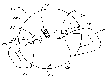
Referring to Figs. 4, S, and 6, one embodiment of the present invention is
illustrated
including tack assembly 15 and retaining member 8. Tack assembly 1 S includes
tack head
16 and elongated tack body I7. Retaining member 8 includes end members IO and
11.
Retaining member 8 can be any shaped retaining member. such as C-shaped. U-
shaped, or
triangular, or any shape that is capable of forming a substantially closed
loop. Tack head I6
includes recessed areas 18 and 20 sized to receive ends 10 and 11,
respectively, of retaining
to member 8. Recessed areas 18 and 20 are disposed on the underside SS of tack
head I6,
which is adjacent elongated tack body 17. End members 10 and 11 are placed
within
recessed areas I 8 and 20, respectively, from underside SS of tack head 16,
prior to elongated
tack body 17 being inserted into a first opening (not shown) in tag body 2.
When elongated
tack body 17 is inserted into tag body 2, the recessed position of retaining
member 8 in tack
head I6 permits the underside 55 of tack head 16 to rest in close proximity to
tag body 2.
Tack head 16 is retained in close enough proximity to tag body 2 such that the
ends 10 and
1 I of retaining member 8 cannot be removed from recessed areas 18 and 20 from
underside
55 of tack head I6.
In the preferred embodiment, tack head I6 is retained substantially flush
against tag
body 2. It is not critical that tack head I6 rest substantially flush against
tag body 2.
However, it is critical that retaining member 8 must not be removable from
underside SS of
tack head 16 when tack assembly 1 S is retained in tag body 2. In addition,
there should be
insufficient space between tack head 16 and tag body 2 for a prying tool to be
used to apply
leverage to tack head i 6 in an attempt to remove tack assembly I S from tag I
. Furthermore,
it is important that ends 10 and 1 I of retaining member 8 cannot be pried
laterally outward,
in a direction substantially perpendicular to elongated tack body I7, from
recessed areas 18
and 20 in tack head 16 when tack assembly 15 is in place in tag 1. If either
end 10 or end 1 I
can be pulled laterally out of recessed area 18 or 20, respectively, then tag
1 could be removed
from an article that is intended to be protected. Therefore, there must be a
mechanism to
3o prevent ends 10 and I 1 from being removed laterally outward from recessed
areas 18 and 20
when the tack assembly I S is in place in tag 1.
7
CA 02351318 2001-05-22
WO 00/32487 PCT/US99/28503 .
In one embodiment. end members 10 and 11 of retaining member 8 are shaped to
form
shoulders that can mate against corresponding shoulders or other blocking
members within
the recessed areas 18 and 20 in tack head 16. In the preferred embodiment, end
members 10
and 11 are substantially spherical in shape forming shoulders SO and 52,
respectively.
Recessed areas 18 and 20 can include shoulders or blocking members 54 and S6,
which are
sized to engage shoulders 50 and 52, respectively, and prevent lateral removal
of ends 10 and
1 l, respectively, as best illustrated in Fig. 5. Alternately, shoulders 54
and 56 can be any
blocking mechanism within recessed areas I 8 and 20 that prevent lateral
removal of ends I O
and 1 i .
t0 As illustrated in Fig. 4, in one embodiment, the diameter of retaining
member 8 can
be made uniform throughout from end 10 to end 11 with the exception of
recessed sections
12 and I4. Recessed sections 12 and 14 are used to form shoulders 50 and 52.
As stated,
shoulders 50 and 52 are used to prevent unauthorized lateral removal of
retaining member 8
from.tack head 16 when in place in tag body 2. Alternately, instead of
recessed areas 12 and
i5 14, the spherical ends 10 and 1 I can be made larger in diameter, which
would form shoulders
(not shown but analogous to shoulders 50 and S2) that would be utilized in a
similar manner
as shoulders SO and S2. In addition, ends 10 and 11 of retaining member 8 can
have shapes
other than spherical, which form shoulders that engage corresponding blocking
members
within recessed areas i 8 and 20 preventing retaining member 8 from lateral
removal from tack
2o head 16 when assembled together with tag I.
Therefore, unauthorized personnel cannot remove retaining rr~ember 8 once tack
assembly 15 is properly retained in place in tag 1. Because of the clutching
mechanism within
tag 1, tack body 17 cannot be pulled free from tag body 2 without the proper
release tool.
Blocking members S4 and 56 within tack head l6 are sized to engage shoulders
50 and 52,
25 respectively, should an attempt be made to pry the end members 10 and 11 of
retaining
member 8 laterally outward from the recessed areas 18 and 20 within tack head
I6.
Any known clutching mechanism can be utilized within tag I for retaining tack
body
17 provided that the tack head 16 is positioned in close enough proximity to
the tag body 2
such that ends 10 and 1 I of retaining member 8 cannot be removed from
recessed areas 18
30 and 20 from underside SS of tack head 16. A plurality of clutching
mechanisms are known
in the art, many of which can be adapted for use with the present invention.
As described
8
CA 02351318 2006-08-30
77496-68
herein above. an example of a specific clutching mechanism usable with the
present invention
is fully described in the '419 patent.
Referring to Fig, 6, retaining member 8 preferably can rotate approximately
I80
degrees relative to tack head 16, with an axis of rotation perpendicular to
tack body 17, as
shown b~~ reference numeral A. Tack body 17 along with attached tack head 16
preferably
rotates within the clutching mechanism 360 degrees relative to the tag body 2,
with an axis
of rotation collinear with tack body 17. Therefore, retaining member 8 and can
rotate 360
degrees relative to tag I , as shown by reference numeral B. The rotation of
retaining member
8, 360 degrees relative to tag body 2 and l80 degrees relative to tack head
I6, permits a
o plurality of attachment positions for tag 1, and provides further protection
against
unauthorized removal by reducing possible positions for applying leverage
against tack head
I 6.
Referring to Fig. 7, in operation, retaining member 8 can be passed through a
suitable
opening in an article to be protected and/or identified. In Lhe example
illustrated in Fig. 7,
retaining member 8 is passed through a portion of shoe 2I , End members 10 and
1 I of
retaining member 8 are then placed into recessed areas I 8 and 20,
respectively, of tack head
16. Tack body T7 is next inserted into a first opening (not shown) in tag body
2, and tack
assembly I5 and tag 1 are pressed together until underside 55 of tack head 16
is properly
seated relatively flush against tag body 2.
In a similar manner, retaining member 8 can be either inserted through a
suitable
opening in, or placed around a suitable portion of, a variety of different
articles to be protected
and/or identified. However, certain articles may not be suitable for tag
attachment in this
manner, and may require the use of a lanyard 13, as illustrated in Fig. 8.
Lanyard 13 is
preferably made of hardened wire, but can be made of any suitable semi-
flexible material that
z5 is difficult to cut and/or break. Loops 61 are formed at each end and can
be made by
attachment collars 60, which can be compressible, solderable, or bondable, as
known in the
art. Lanyard 13 can be made nearly an5~ diameter and/or length suitable for
the particular
application intended.
Referring to Fig. 9, for certain applications, lanyard 22 can be constructed
having
3o spherical end members 24, which are then placed into recessed areas 18 and
?0 in tack head
I 6 in analogous manner to end members 10 and 11 of retaining member 8. End
members 24
9
CA 02351318 2001-05-22
WO UO/32487 PCTIUS99I28503 '~
are attached to lanyard 22 by attachment collars 58, which.are similar to
collars 60. Lanyard
22 can be made nearly any length and diameter. As with end members 10 and 11,
spherical
end members 24 can be made a shape other than spherical provided that a
mechanism is
provided to prevent the lateral removal of end members 24 from recessed areas
18 and 20 in
tack head 16 when tack assembly 15 is in place in tag 1.
Referring to Fig. 10, in an alternate embodiment, one end of lanyard 23 can
have loop
26 attached instead of a second sphere 25. Spherical end member 25 is attached
at collar 59,
and is identical to end member 24 and collar 58. As with end members 24, the
specific shape
of end member 25 can be other than spherical.
Io Loop 26 is sized just large enough to permit passage of sphere 25, but
small enough
to prevent passage of tag 1 through loop 26. By passing sphere 25 through loop
26 and into
one of the recessed areas 18 or 20 in tack head 16, a large loop in lanyard 23
can be formed
to wrap around suitable articles to be protected.
Referring to Fig. 11, an alternate embodiment of the retaining member is
illustrated
as rigid loop 60 having a single end member 62 with shoulder 64. End member 62
can be
placed into recessed area 18 or 20 in tack head 16 and functions similarly to
end members 10
and I 1 described above. Loop 60 can be welded, soldered, or bonded at 66 :f
desired. As
with the end members described in the other embodiments ofretaining members,
end member
62 can be other than spherical.
Referring to Fig. 12, for the embodiments of retaining members having a single
end
member, such as lanyard 23, rigid loop 60, and others contemplated by the
present invention,
a modified tack head 68 can be made with only one recessed area 70 to receive
end members
24 or 62, respectively, or others not shown but contemplated herein. Elongated
tack body 69
is identical to tack body 17. Recessed area 70 can include a shoulder 72 or
other blocking
member to prevent the lateral removal of the inserted end member of the
associated retaining
member.
The specific blocking member disposed within the recessed area or recessed
areas
within the tack head will be determined by the structure of the end member or
end members
of the associated retaining member. The spherical shape of the end members,
and
3o corresponding shaped recessed areas used herein as examples are believed to
be the best mode
for practicing the invention. However, other blocking mechanisms are
contemplated for
CA 02351318 2001-05-22
WO 00132487 PCT/US99I28503 .
preventing the lateral removal of the end members of the retaining member from
the tack
head.
For example, referring to Figs. 13, 14, and 15, retaining member 30 includes
end
members 32 that are elbow portions or simply bent continuations of member 30.
Tack head
34 includes recessed areas 36 and 38, which are sized to receive retaining
member 30 so that
tack head 34 can rest relatively flush against tag body 2. Recessed areas 38
are substantially
perpendicular to recessed areas 36, and extend deeper into tack head 34 than
recessed areas
36 to accommodate end members 32. As in the preferred embodiment described
above, when
tack head 34 is in place adjacent tag body 2, there must be insufficient space
between tack
1o head 34 and tag body 2 for removal of retaining member 30 from underneath
tack head 34,
and for insertion of a prying tool.
In addition, an unauthorized person will not be able to laterally remove
retaining
member 30 from tack head 34 because blocking members 39 in recessed areas 38
will stop
end members 32. The exterior walls 37 ofrecessed areas 38 can form blocking
members 39.
15 When retaining member 30 is pulled laterally outward from tack head 34,
interior surface 33
of end member 32 abuts against and is stopped by blocking member 39, thus
preventing
lateral removal of end members 32 from recessed areas 38. Blocking members 39
can be
formed by other structures such as pins, bars or other structure that prevents
removal of end
members 32 (not shown), with walls 37 being the preferred embodiment for
blocking member
20 39.
Retaining member 30 preferably can rotate 180 degrees in relation to tack head
34,
with an axis of rotation perpendicular to elongated tack body 35, as
illustrated by the arrows
in Fig. 15. Tack body 35 preferably will be able to rotate, within the
clutching mechanism in
tag body 2, 360 degrees relative to tag I, permitting tack head 34 and
retaining member 30 to
25 also rotate 360 degrees with an axis of rotation being collinear with
elongated tack body 35.
It is to be understood that variations and modifications of the present
invention can be
made without departing from the scope of the invention. It is also to be
understood that the
scope of the invention is not to be interpreted as limited to the specific
embodiments disclosed
herein, but only in accordance with the appended claims when read in light of
the forgoing
30 disclosure.
11