Sélection de la langue

Search

Sommaire du brevet 2352119 

Énoncé de désistement de responsabilité concernant l'information provenant de tiers

Une partie des informations de ce site Web a été fournie par des sources externes. Le gouvernement du Canada n'assume aucune responsabilité concernant la précision, l'actualité ou la fiabilité des informations fournies par les sources externes. Les utilisateurs qui désirent employer cette information devraient consulter directement la source des informations. Le contenu fourni par les sources externes n'est pas assujetti aux exigences sur les langues officielles, la protection des renseignements personnels et l'accessibilité.

Disponibilité de l'Abrégé et des Revendications

L'apparition de différences dans le texte et l'image des Revendications et de l'Abrégé dépend du moment auquel le document est publié. Les textes des Revendications et de l'Abrégé sont affichés :

  • lorsque la demande peut être examinée par le public;
  • lorsque le brevet est émis (délivrance).
(12) Demande de brevet: (11) CA 2352119
(54) Titre français: EMBOUT DE SECHE-CHEVEUX A CONFIGURATION VARIABLE
(54) Titre anglais: HAIRDRYER NOZZLE WITH VARIABLE CONFIGURATION
Statut: Réputée abandonnée et au-delà du délai pour le rétablissement - en attente de la réponse à l’avis de communication rejetée
Données bibliographiques
Abrégés

Abrégé français

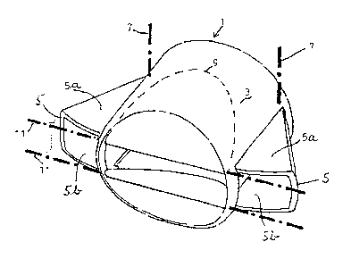
Embout, amovible ou non, destiné à un sèche-cheveux, qui peut être modifié aisément depuis une première configuration fournissant un flux d'air chaud présentant une section sensiblement ronde, jusqu'à l'obtention d'un flux d'air à section sensiblement rectangulaire, c'est-à-dire large et plate. Cet embout est constitué par une virole (3), équipée de deux tiroirs (5) pouvant effectuer un mouvement de pivotement axial par rapport à des axes géométriques (7) et de volets (9) pouvant effectuer un mouvement de pivotement par rapport à des axes géométriques (11) perpendiculaires aux axes de pivotement (7) des tiroirs (5).


Abrégé anglais


The invention concerns a nozzle, detachable or not, designed for a hairdryer,
which can be easily modified from a first configuration supplying a hot air
stream with a substantially circular cross-section to obtain an air stream
substantially rectangular, that is wide and flat, in cross-section. Said
nozzle consists of a ferrule (3) provided with two slots (5) capable of
pivoting relatively to geometrical axes (7) and flaps (9) capable of producing
a pivoting motion relatively to geometrical axes (11) perpendicular to the
pivot pins (7) of the slots (5).

Revendications

Note : Les revendications sont présentées dans la langue officielle dans laquelle elles ont été soumises.


-6-
CLAIMS
1. Detachable or not detachable nozzle for hair dryer, comprising a sleeve (3)
and
bending means of said nozzle to change in a reversible manner from a first
configuration (A) of
a stream of hot air coming out of said hair dryer with an approximately
circular cross section to
a second configuration (B) of a stream hot air with an approximately
rectangular cross section,
that is to say broad and flat, characterized in that said bending means
essentially comprise two
folding wings (5) incorporated in the sleeve (3), making an axial pivoting
movement about
geometrical axes (7), and flaps (9), making a pivoting movement about
geometrical axes (11)
perpendicular to said pivoting axes (7) of the folding wings (5), at the time
of the change from
the first configuration (A) to the second configuration (B) of the stream of
hot air and vice versa.
2. Nozzle according to Claim 1, characterized in that, in the approximately
circular
configuration of the stream of air, the flaps (9) are parallel to the axis of
the sleeve (3) and the
folding wings (5) are in, the upper walls (5a) of the two folding wings slide
under the upper flap
and the lower walls (5b) of these same folding wings cover the lower flap.
3. Nozzle according to Claim 2, characterized in that in the approximately
rectangular configuration of the stream of air, the folding wings (5) are
pivoted about the
geometrical axes (7) in such a way as to flatten the outlet orifice and the
flaps (9) are raised in
such a way as to position themselves, by pivoting about the geometrical axes
(11), on the inside
of the sleeve (3).
4. Nozzle according to any one of Claims 1 to 3, characterized in that springs
keep
the flaps (9) and the folding wings (5) in the position corresponding to a
stream of air of
approximately rectangular cross section.
5. Nozzle according to Claim 4, characterized in that a ring whose diameter is
slightly greater than that of the sleeve (3) is provided in order to be slid
in such a way as to cover
the folding wings (5) progressively from the rear to the front in order to
push the folding wings

-7-
back in against the force of the spring and bring the flaps (9) into line with
the axis of the sleeve
(3).
6. Use of the nozzle according to any one of Claims 1 to 5, characterized in
that the
nozzle is an integral part of a hair dryer.
7. Use of the nozzle according to any one of Claims 1 to 5, characterized in
that the
nozzle is fitted to the outlet orifice of a hair dryer in a detachable manner.

Description

Note : Les descriptions sont présentées dans la langue officielle dans laquelle elles ont été soumises.


CA 02352119 2001-05-25
-2-
VARIABLE-CONFIGURATION HAIR DRYER NOZZLE
SubLect of the invention
The present invention relates to a hair dryer nozzle whose shape can be
modified
to deliver either an essentially cylindrical stream of air, that is with a
circular cross section, or
a stream of air in the form of a relatively broad flat lamina.
Technological background of the invention
Electric hair dryers are designed to produce a stream of air which is heated
by an
electric resistance and is delivered by the hair dryer which is fitted with a
fan for this purpose.
The very design of the hair dryer, in particular its cylindrical circular-
section
geometry which must house a rotary fan, gives the stream of air a circular
cross section.
In certain cases, however, users want a relatively broad and flat lamina of
air.
It is therefore usual practice to fit a nozzle on the outlet end where the
stream of
air is produced. The nozzle ends in a flattened outlet generally in the form
of an elongated
rectangle, in order to create a broad and flat lamina of air.
A nozzle of this kind can be fitted permanently to the outlet opening of the
hair
dryer, but it is usually detachable.
In the case of a detachable nozzle, the user may mislay it, or at any rate has
the
nuisance of looking after an extra component which is sometimes difficult to
store.
While the hair dryer is in use, the circular stream and the broad flat stream
are
found to be alternately necessary and oblige the user to remove and replace
the nozzle. This
quickly becomes a nuisance, especially as it is hot.
The prior art includes a number of teachings regarding the configurations of
air
flow in the hair dryers. In particular, French document FR-A-2 640 857
provides a nozzle device
made of a flexible material. A reversible bending of the nozzle is controlled
by a ring whose
rotation causes, by activating an internal mechanism, the change from a
cylindrical configuration
to a flat and oblong configuration, so as to create a laminar air flow.

CA 02352119 2001-05-25
-3 -
Objects of the invention
The object of the present invention is to provide a detachable or non-
detachable
nozzle for a hair dryer that can easily be modified from a first configuration
delivering a stream
of hot air circular cross section, until a stream of air is produced with an
approximately
rectangular cross section, that is to say broad and flat.
The term "rectangular" must be understood as including shapes having slightly
circular or even oval-like corners or sides. Similarly the term "circular" can
be applied to slightly
oval shapes.
The drawbacks of the prior art caused by the fact that when the hair dryer is
in
use, the standard circular stream and the broad flat stream are found to be
alternately necessary,
which obliges the user to remove and replace the nozzle, which is hot, can in
this way be
avoided.
More specifically, the obj ect of the invention is to produce a mechanism that
can
be fitted to or is integral with the hair dryer, in order to make it easy to
have a nozzle of variable
shape such that it is capable of delivering a circular-sectioned stream of air
as well as a broad and
flat stream of air.
The invention will be described in greater detail with referenceto certain
preferred
embodiments illustrated hereinafter in the appended drawings
Brief description of the figures
Figure 1 shows a perspective view of a nozzle in a first position producing a
stream of hot
air of circular cross section.
Figure 2 is a view corresponding to Figure 1 in which the nozzle releases a
stream of hot
air in the form of a broad flat lamina.
Figures3 and4showotherperspectiveviewssimilartoFigures 1 and2,respectively,
which
show more clearly the movement of the flaps with which the hair-dryer nozzle
is fitted.
Description of a preferred embodiment of the invention
The nozzle having the general reference 1 may be an integral part of a hair
dryer
or a separate item which can be fitted to an existing hair dryer.

CA 02352119 2001-05-25
-4-
The very design of a hair dryer means in principle that it delivers a stream
of air
of circular cross section.
The nozzle 1 consists of a cylindrical or frustoconical sleeve 3, one end of
which
is either an integral part of a hair dryer (not shown), or can be fitted to
the outlet orifice of a hair
dryer.
In one position (Figures 1 and 3), the stream of air released at the outlet of
the
nozzle is of a practically circular cross section.
For certain applications, however, the user wants a stream of air in the form
of a
relatively broad flat lamina.
To produce this effect, the sleeve 3 is fitted with two folding wings 5
capable of
making a pivoting movement about geometrical axes 7, and with flaps 9 capable
of making a
pivoting movement about geometrical axes 11 perpendicular, in principle, to
the pivot axes 7 of
the folding wings 5.
In the position shown in Figures 1 and 3, the flaps 9 are parallel to the axis
ofthe
stream of air corresponding to the shape of the sleeve 3, and the folding
wings S are in. As
illustrated, the upper walls Sa of the two folding wings slide under the upper
flap and the lower
walls Sb of these same folding wings cover the lower flap.
In this configuration, the stream of hot air continues to maintain a circular
cross
section which is simply divided into three longitudinal slices in the sleeve
3.
The configuration of the sides of the folding wings may of course be adapted
to
be slightly circular so as to match the general circular shape of the sleeve 3
when folded away.
To bring about the indicated pivoting movement of the folding wings and flaps
about their respective axes 7 and 1 1, pivots or any suitable equivalent means
may be provided.
In order to modify the configuration of the nozzle, the folding wings 5 can be
pivoted about the geometrical axes 7 in such a way as to flatten the outlet
orifice until the
position shown in Figures 2 and 4 is arrived at.
Simultaneously, the flaps 9 are raised in such a way as to position
themselves, by
pivoting about the geometrical axes 11, on the inside of the sleeve 3. The
initially circular-
sectioned stream of air therefore strikes the flaps 9 and is directed towards
the axis of the sleeve
3.

CA 02352119 2001-05-25
-5-
Simultaneously the stream of air can also diverge to the left and right,
following
the sides of the now open folding wings 5, giving a stream of air which is of
a generally
rectangular shape as illustrated.
Any appropriate means can be used to bring about this modification.
Springs (not shown) may for example be used to act on the flaps 9 and folding
wings 5 to keep them in the position shown in Figures 2 and 4. When a force is
applied, for
example with the aid of a ring (not shown) whose diameter is slightly greater
than that of the
sleeve 3 and which is slid so as to cover the folding wings 5 progressively
from the rear to the
front, it becomes possible, against the force of the spring, to push the
folding wings towards the
position shown in Figures 1 and 3. Simultaneously the flaps 9 can be brought
into line with the
axis of the sleeve 3.
Other means may of course be used.
There is no difficulty in designing the shape of the flaps to perform the
desired
function, which is to position themselves on the inside of the sleeve and
deflect virtually all the
air.
The folding wings can also easily be folded, with practically no interference
with
the movement of the flaps 9.
A slight fillet may be provided, either on the folding wings (the extremities
of the
upper face or lower face) or on the flaps if necessary.
In practice, it is found that the modification occurs very easily without
excessive
friction and without significant loss of cross-sectional opening for the
passage of the stream of
air, when switching from the position in Figure 1 to that in Figure 3. The
folding side wings can,
if of appropriate dimensions, maintain a reasonable cross section for the air
stream when
flattened, which corresponds, in this case, to about two thirds of the
circular cross section.

Dessin représentatif
Une figure unique qui représente un dessin illustrant l'invention.
États administratifs

2024-08-01 : Dans le cadre de la transition vers les Brevets de nouvelle génération (BNG), la base de données sur les brevets canadiens (BDBC) contient désormais un Historique d'événement plus détaillé, qui reproduit le Journal des événements de notre nouvelle solution interne.

Veuillez noter que les événements débutant par « Inactive : » se réfèrent à des événements qui ne sont plus utilisés dans notre nouvelle solution interne.

Pour une meilleure compréhension de l'état de la demande ou brevet qui figure sur cette page, la rubrique Mise en garde , et les descriptions de Brevet , Historique d'événement , Taxes périodiques et Historique des paiements devraient être consultées.

Historique d'événement

Description Date
Inactive : IPRP reçu 2008-01-10
Demande non rétablie avant l'échéance 2004-12-07
Le délai pour l'annulation est expiré 2004-12-07
Réputée abandonnée - omission de répondre à un avis sur les taxes pour le maintien en état 2003-12-08
Inactive : Page couverture publiée 2001-09-24
Lettre envoyée 2001-09-19
Inactive : CIB en 1re position 2001-08-26
Inactive : Transfert individuel 2001-08-14
Inactive : Lettre de courtoisie - Preuve 2001-08-07
Inactive : Notice - Entrée phase nat. - Pas de RE 2001-08-01
Demande reçue - PCT 2001-07-27
Demande publiée (accessible au public) 2000-06-15

Historique d'abandonnement

Date d'abandonnement Raison Date de rétablissement
2003-12-08

Taxes périodiques

Le dernier paiement a été reçu le 2002-12-06

Avis : Si le paiement en totalité n'a pas été reçu au plus tard à la date indiquée, une taxe supplémentaire peut être imposée, soit une des taxes suivantes :

  • taxe de rétablissement ;
  • taxe pour paiement en souffrance ; ou
  • taxe additionnelle pour le renversement d'une péremption réputée.

Les taxes sur les brevets sont ajustées au 1er janvier de chaque année. Les montants ci-dessus sont les montants actuels s'ils sont reçus au plus tard le 31 décembre de l'année en cours.
Veuillez vous référer à la page web des taxes sur les brevets de l'OPIC pour voir tous les montants actuels des taxes.

Historique des taxes

Type de taxes Anniversaire Échéance Date payée
Taxe nationale de base - générale 2001-05-25
Enregistrement d'un document 2001-08-14
TM (demande, 2e anniv.) - générale 02 2001-12-07 2001-10-04
TM (demande, 3e anniv.) - générale 03 2002-12-09 2002-12-06
Titulaires au dossier

Les titulaires actuels et antérieures au dossier sont affichés en ordre alphabétique.

Titulaires actuels au dossier
FACO S.A.
Titulaires antérieures au dossier
HENRI SMAL
Les propriétaires antérieurs qui ne figurent pas dans la liste des « Propriétaires au dossier » apparaîtront dans d'autres documents au dossier.
Documents

Pour visionner les fichiers sélectionnés, entrer le code reCAPTCHA :


Pour visualiser une image, cliquer sur un lien dans la colonne description du document. Pour télécharger l'image (les images), cliquer l'une ou plusieurs cases à cocher dans la première colonne et ensuite cliquer sur le bouton "Télécharger sélection en format PDF (archive Zip)" ou le bouton "Télécharger sélection (en un fichier PDF fusionné)".

Liste des documents de brevet publiés et non publiés sur la BDBC .

Si vous avez des difficultés à accéder au contenu, veuillez communiquer avec le Centre de services à la clientèle au 1-866-997-1936, ou envoyer un courriel au Centre de service à la clientèle de l'OPIC.


Description du
Document 
Date
(aaaa-mm-jj) 
Nombre de pages   Taille de l'image (Ko) 
Dessin représentatif 2001-09-10 1 9
Description 2001-05-24 4 185
Revendications 2001-05-24 2 61
Abrégé 2001-05-24 1 20
Dessins 2001-05-24 2 40
Avis d'entree dans la phase nationale 2001-07-31 1 194
Rappel de taxe de maintien due 2001-08-07 1 116
Courtoisie - Certificat d'enregistrement (document(s) connexe(s)) 2001-09-18 1 136
Courtoisie - Lettre d'abandon (taxe de maintien en état) 2004-02-01 1 176
Rappel - requête d'examen 2004-08-09 1 117
Correspondance 2001-07-31 1 24
PCT 2001-05-24 19 736
Taxes 2002-12-05 1 34
Taxes 2001-10-03 1 33
PCT 2001-05-25 11 401