Sélection de la langue

Search

Sommaire du brevet 2353433 

Énoncé de désistement de responsabilité concernant l'information provenant de tiers

Une partie des informations de ce site Web a été fournie par des sources externes. Le gouvernement du Canada n'assume aucune responsabilité concernant la précision, l'actualité ou la fiabilité des informations fournies par les sources externes. Les utilisateurs qui désirent employer cette information devraient consulter directement la source des informations. Le contenu fourni par les sources externes n'est pas assujetti aux exigences sur les langues officielles, la protection des renseignements personnels et l'accessibilité.

Disponibilité de l'Abrégé et des Revendications

L'apparition de différences dans le texte et l'image des Revendications et de l'Abrégé dépend du moment auquel le document est publié. Les textes des Revendications et de l'Abrégé sont affichés :

  • lorsque la demande peut être examinée par le public;
  • lorsque le brevet est émis (délivrance).
(12) Brevet: (11) CA 2353433
(54) Titre français: CAPTEUR OPTIQUE DE BALAYAGE A LENTILLES CONCENTRIQUES, ET A TRES GRANDE LARGEUR DE CHAMP
(54) Titre anglais: ULTRA-WIDE FIELD OF VIEW CONCENTRIC SCANNING SENSOR SYSTEM
Statut: Périmé et au-delà du délai pour l’annulation
Données bibliographiques
(51) Classification internationale des brevets (CIB):
  • G2B 13/06 (2006.01)
(72) Inventeurs :
  • CHEN, CHUNGTE W. (Etats-Unis d'Amérique)
  • ANDERSON, J. STEVE (Etats-Unis d'Amérique)
(73) Titulaires :
  • RAYTHEON COMPANY
(71) Demandeurs :
  • RAYTHEON COMPANY (Etats-Unis d'Amérique)
(74) Agent: MARKS & CLERK
(74) Co-agent:
(45) Délivré: 2003-12-23
(86) Date de dépôt PCT: 2000-10-05
(87) Mise à la disponibilité du public: 2001-04-12
Requête d'examen: 2001-06-01
Licence disponible: S.O.
Cédé au domaine public: S.O.
(25) Langue des documents déposés: Anglais

Traité de coopération en matière de brevets (PCT): Oui
(86) Numéro de la demande PCT: PCT/US2000/027476
(87) Numéro de publication internationale PCT: US2000027476
(85) Entrée nationale: 2001-06-01

(30) Données de priorité de la demande:
Numéro de la demande Pays / territoire Date
09/413,688 (Etats-Unis d'Amérique) 1999-10-07

Abrégés

Abrégé français

L'invention porte sur un capteur optique de balayage à lentilles concentriques très compact à grande ouverture numérique, à résolution élevée, et à très grande largeur de champ. Ledit capteur comporte une lentille hémisphérique de balayage présentant une surface arrière plane réfléchissante, des lentilles en coque extérieure et intérieure et une surface linéaire en réseau focalisée. Les lentilles coques sont disposées concentriquement par rapport au centre de la lentille hémisphérique de balayage, tandis que la surface linéaire en réseau l'est autour du centre de la lentille coque intérieure. Le capteur peut jouer le rôle d'une lentille sphérique à plusieurs surfaces réfléchissantes permettant un balayage à facettes.


Abrégé anglais


A very compact, high numerical aperture, high resolution, ultra-wide field of
view concentric scanning optical sensor. The concentric scanning optical
sensor includes a scanning half ball lens having a flat reflective rear
surface, outer and inner shell lenses, and a linear focal surface array. The
outer shell lens and linear inner shell lens are concentrically disposed about
the center of the scanning half ball lens. The linear focal surface array is
disposed along a focal surface of the inner shell lens. The scanning optical
sensor may also use a full spherical ball with multiple reflecting surfaces to
allow for multiple facet scanning.

Revendications

Note : Les revendications sont présentées dans la langue officielle dans laquelle elles ont été soumises.


6
CLAIMS
What is claimed is:
1. An ultra-wide field concentric scanning sensor comprising:
a rotatable half ball lens having a flat reflective surface;
a outer shell lens concentrically disposed with respect to the half ball lens;
a linear inner shell lens concentrically disposed with respect to the half
ball lens; and
a linear focal surface array disposed along a focal surface of the inner shell
lens.
2. The sensor recited in Claim 1 wherein the focal surface array is curved.
3. The sensor recited in Claim 1 wherein the half ball lens is rotatable to
scan the
field of view.
4. The sensor recited in Claim 1 wherein the flat surface of the half ball
lens is a
reflective Schmidt corrector with generalized aspheric shape.
5. The sensor recited in Claim 1 wherein the flat surface of the half ball
lens is a
reflective Schmidt corrector with generalized bilateral symmetric aspheric
shape.
6. The sensor recited in Claim 1 wherein the focal surface array is curved and
concentric with respect to the center of the half ball lens.
7. The sensor recited in Claim 1 wherein the focal surface array has detector
elements
distributed along a ring centered around an optical axis of the sensor.
8. The sensor recited in Claim 1 wherein the focal surface array comprises
multiple
stripes that are concentric with respect to the center of the half ball lens.
9. The sensor recited in Claim 1 further comprising:
a second rotatable half ball lens having a flat reflective surface disposed
adjacent to the rotatable half ball lens to form a full ball lens.

Description

Note : Les descriptions sont présentées dans la langue officielle dans laquelle elles ont été soumises.

CA 02353433 2001-06-O1
WO 01/25832 PCT/US00/27476
ULTRA-WIDE FIELD OF VIEW CONCENTRIC
SCANNING SENSOR SYSTEM
GOVERNMENT RIGHTS
This invention was made with Government support under Contract No. N66001-98-
C-86?2 awarded by the Department of the Navy. The government has certain
rights in this
invention.
BACKGROUND
The present invention relates generally to scanning electro-optical sensor
systems, and
more particularly, to ultra-wide field of view concentric scanning electro-
optical sensor
systems.
Most wide field of view scanning electro-optical systems have either a fisheye
lens
form or concentric Bouwers system. For a fisheye lens system, the overall
length is at least
six times the effective focal length (EFL). Consequently, the fisheye lens
systems are bulky
and heavy. In many cases, aspheric lenses are needed for both aberration and
distortion
correction. Additionally, the implementation of a scanner near the pupil plane
or aperture
stop is a challenging task.
Although the Bouwers system is a concentric design form, the overall length is
two
times the EFL. Additionally, the generic central obscuration characteristics
associated with
the Bouwers system often limits the F-number and the field of view coverage.
Therefore, a
scanner near the aperture has to be decentered with respect to the optical
axis.

CA 02353433 2001-06-O1
WO 01/25832 PCT/US00/27476
7
Accordingly, it is an objective of the present invention to provide for ultra-
wide field
of view concentric scanning electro-optical sensor systems that improve upon
conventional
fisheye lens and Bouwers type systems.
SUMMARY OF THE INVENTION
To accomplish the above and other objectives, the present invention provides
for a
very compact, high numerical aperture, high resolution, ultra-wide field of
view (FOV)
concentric scanning optical sensor. The drawbacks associated with the prior
art systems may
be overcome by the concentric scanning optical sensor constructed in
accordance with the
principles of the present invention.
The concentric scanning optical sensor comprises a scanning half ball lens
having a
flat reflective rear surface, an outer shell lens that is concentrically
disposed about the
scanning half ball lens, a relatively thin inner shell lens that is
concentrically disposed about
the scanning half ball lens, and a linear focal surface array that is
concentrically disposed
1~ about the scanning half ball lens.
The scanning half ball lens is rotated to scan the field of view. The flat
surface of the
half ball lens may be a reflective Schmidt corrector with generalized aspheric
shape. The flat
surface of the half ball lens may be a reflective Schmidt corrector with
generalized bilateral
symmetric aspheric shape. The scanning mechanism may also be a full spherical
ball with
multiple reflecting surfaces to allow for multiple facet scanning.
The focal surface array may be a curved and concentric with respect to the
center of
the scanning half ball lens. The focal surface array may be coplanar with
detector elements
distributed along a ring centered around the optical axis of the sensor. The
focal surface array
may also include multiple stripes concentric with respect to the center of the
half ball lens.
BRIEF DESCRIPTION OF THE DRAWINGS
The various features and advantages of the present invention may be more
readily un-
derstood with reference to the following detailed description taken in
conjunction with the
accompanying drawings, wherein like reference numerals designate like
structural element,
and in which:
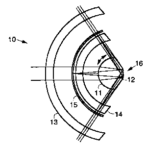
Fig. 1 illustrates a cross-sectional top view of an exemplary very compact,
high
numerical aperture, high resolution, ultra-wide field of view concentric
scanning optical
sensor in accordance with the principles of the present invention;

CA 02353433 2001-06-O1
WO 01/25832 PCT/US00/27476
3
Fig. 2 illustrates a cross-sectional side view of the exemplary sensor shown
in Fig. 1;
and
Fig. 3 illustrates a cross-sectional top view of a second exemplary scanning
optical
sensor in accordance with the principles of the present invention.
DETAILED DESCRIPTION
Referring to the drawing figures, Fig. 1 illustrates a cross-sectional top
view of an
exemplary very compact, high numerical aperture, high resolution, ultra-wide
field of view
concentric scanning optical sensor 10 in accordance with the principles of the
present
invention. Fig. 2 illustrates a cross-sectional side view of the exemplary
sensor 10 shown in
Fig. 1.
The ultra-wide field of view sensor 10 comprises a rotatable half ball lens 11
having a
flat reflective (mirror) surface 12. An outer shell lens 13 is concentrically
disposed with
respect to the center of the rotatable half ball lens 11. A relatively thin
partial rind like inner
shell lens 14 that is concentrically disposed about the center of the scanning
half ball lens 11.
A linear focal surface array 15 concentric with a focal surface of the inner
shell lens
14. The focal surface array 15 may be either a curved linear array with a
center of curvature
in the proximity of the aperture, or a linear array arranged in a ring shape
concentric with an
optical axis of the sensor 10. Thus, the outer shell lens 13, inner shell lens
14 and linear
focal surface array I S are concentrically disposed with respect to the center
of the rotatable
half ball lens 11.
Rotation of the rotatable half ball lens 11 is illustrated in Fig. 1 which
rotates about an
axis through the center of the ball in the plane of the drawing. In Fig. 2,
the rotatable half
ball lens 11 rotates about an axis through the center of the ball into and out
of the drawing.
In operation, incoming radiation derived from an image scene passes through
the lens
shell outer 13, enters the half ball lens 11, and is reflected by the flat
rear reflective surface 12
of the half ball lens 11. The radiation reflected by the reflective surface 12
of the half ball
lens 11 passes through the inner shell lens 14 and is focused on the focal
surface array 15.
An aperture stop 16 is located at the reflective (mirror) surface 12 of the
half ball lens
11. Since each optical element in the sensor 10 is concentric with respect to
the center of the
aperture stop 16, the image quality is practically identical for every field
point. This
symmetric principle makes the concentric structure of the concentric scanning
optical sensor
IO very simple in terms of both design and fabrication.

CA 02353433 2001-06-O1
WO 01/25832 PCT/USOO/Z7476
4
To reduce the size of the focal surface array 15, a linear detector array 15
in
conjunction with a scanning half ball lens 11 is used to scan the two
dimensional field of
view. The scanning process is accomplished by rotating the half ball tens I I
to scan the field
of view.
The linear focal surface art-ay 15 can have a number of different structures.
The linear
focal surface array 15 may be a curved linear focal surface array I S that
concentrically
disposed with respect to the aperture stop 16 (or the center of the half ball
lens 11). The
linear focal surface array 15 may be a flat linear focal surface array 1~ with
detector elements
distributed on an arc that is concentric with respect to, or centered around,
the optical axis of
the sensor 10. The linear focal surface array 15 may also use any spherical
arrangement of
the detector elements of the focal surface array 15. For example, the focal
surface anray 15
may be comprised of multiple stripes that are concentrically disposed with
respect to the
center of the half ball lens 11.
The flat minor surface 12 of the half ball lens 1 I may comprise a reflective
Schmidt
plate, or reflective Schmidt corrector to provide for residual aberration
correction. The
Schmidt plate may have a generalized aspheric shape or a generalized bilateral
symmetric
shape. This additional degree of freedom in spherical aberration and oblique
spherical
aberration correction allows more choices in glass materials for both the half
ball lens 11 and
the outer and inner shell lenses 13, 14.
The sensor 10 has an overall length approximately equal to its effective focal
length.
More importantly, the optical elements are spherical in shape, and the image
quality is
practically diffraction-limited across the entire field of view.
The field of view coverage of the concentric scanning optical sensor 10 may be
as
large as up to 180 degrees. Notwithstanding this, the volume of the sensor 10
is at least 20
times smaller than that of a corresponding fisheye lens. The large field of
view capability is
ideal for many target acquisition sensor applications.
The concentric scanning optical sensor 10 has broad applications for use in
sensor
systems manufactured by the assignee of the present invention. The high
numerical aperture,
wide field of view and ultra-compact package provided by the present sensor 10
is
particularly suitable for spaceborne and airborne acquisition sensor
applications.
More than one reflective facet may be used in the sensor 10 if the scanning
ball is
made spherical to improve the scanning duty cycle. Fig. 3 illustrates a cross-
sectional top
view of a second exemplary scanning optical sensor 10 in accordance with the
principles of

CA 02353433 2001-06-O1
WO 01/25832 PCT/US00/27476
the present invention. The sensor 10 shown in Fig. 3 employs two half ball
lenses 11
combined into a full sperical ball lens l la.
Thus, ultra-wide field of view concentric scanning electro-optical sensor
systems
have been disclosed. It is to be understood that the above-described
embodiments are merely
S illustrative of some of the many specific embodiments that represent
applications of the
principles of the present invention. Clearly, numerous and other arrangements
can be readily
devised by those skilled in the art without departing from the scope of the
invention.

Dessin représentatif
Une figure unique qui représente un dessin illustrant l'invention.
États administratifs

2024-08-01 : Dans le cadre de la transition vers les Brevets de nouvelle génération (BNG), la base de données sur les brevets canadiens (BDBC) contient désormais un Historique d'événement plus détaillé, qui reproduit le Journal des événements de notre nouvelle solution interne.

Veuillez noter que les événements débutant par « Inactive : » se réfèrent à des événements qui ne sont plus utilisés dans notre nouvelle solution interne.

Pour une meilleure compréhension de l'état de la demande ou brevet qui figure sur cette page, la rubrique Mise en garde , et les descriptions de Brevet , Historique d'événement , Taxes périodiques et Historique des paiements devraient être consultées.

Historique d'événement

Description Date
Représentant commun nommé 2019-10-30
Le délai pour l'annulation est expiré 2019-10-07
Lettre envoyée 2018-10-05
Accordé par délivrance 2003-12-23
Inactive : Page couverture publiée 2003-12-22
Préoctroi 2003-10-03
Inactive : Taxe finale reçue 2003-10-03
Un avis d'acceptation est envoyé 2003-04-11
month 2003-04-11
Lettre envoyée 2003-04-11
Inactive : Approuvée aux fins d'acceptation (AFA) 2003-03-28
Modification reçue - modification volontaire 2002-02-07
Inactive : Page couverture publiée 2001-09-28
Modification reçue - modification volontaire 2001-09-14
Inactive : CIB en 1re position 2001-09-06
Inactive : Acc. récept. de l'entrée phase nat. - RE 2001-08-13
Lettre envoyée 2001-08-13
Demande reçue - PCT 2001-08-10
Toutes les exigences pour l'examen - jugée conforme 2001-06-01
Exigences pour une requête d'examen - jugée conforme 2001-06-01
Demande publiée (accessible au public) 2001-04-12

Historique d'abandonnement

Il n'y a pas d'historique d'abandonnement

Taxes périodiques

Le dernier paiement a été reçu le 2003-09-23

Avis : Si le paiement en totalité n'a pas été reçu au plus tard à la date indiquée, une taxe supplémentaire peut être imposée, soit une des taxes suivantes :

  • taxe de rétablissement ;
  • taxe pour paiement en souffrance ; ou
  • taxe additionnelle pour le renversement d'une péremption réputée.

Les taxes sur les brevets sont ajustées au 1er janvier de chaque année. Les montants ci-dessus sont les montants actuels s'ils sont reçus au plus tard le 31 décembre de l'année en cours.
Veuillez vous référer à la page web des taxes sur les brevets de l'OPIC pour voir tous les montants actuels des taxes.

Titulaires au dossier

Les titulaires actuels et antérieures au dossier sont affichés en ordre alphabétique.

Titulaires actuels au dossier
RAYTHEON COMPANY
Titulaires antérieures au dossier
CHUNGTE W. CHEN
J. STEVE ANDERSON
Les propriétaires antérieurs qui ne figurent pas dans la liste des « Propriétaires au dossier » apparaîtront dans d'autres documents au dossier.
Documents

Pour visionner les fichiers sélectionnés, entrer le code reCAPTCHA :


Pour visualiser une image, cliquer sur un lien dans la colonne description du document (Temporairement non-disponible). Pour télécharger l'image (les images), cliquer l'une ou plusieurs cases à cocher dans la première colonne et ensuite cliquer sur le bouton "Télécharger sélection en format PDF (archive Zip)" ou le bouton "Télécharger sélection (en un fichier PDF fusionné)".

Liste des documents de brevet publiés et non publiés sur la BDBC .

Si vous avez des difficultés à accéder au contenu, veuillez communiquer avec le Centre de services à la clientèle au 1-866-997-1936, ou envoyer un courriel au Centre de service à la clientèle de l'OPIC.

({010=Tous les documents, 020=Au moment du dépôt, 030=Au moment de la mise à la disponibilité du public, 040=À la délivrance, 050=Examen, 060=Correspondance reçue, 070=Divers, 080=Correspondance envoyée, 090=Paiement})


Description du
Document 
Date
(aaaa-mm-jj) 
Nombre de pages   Taille de l'image (Ko) 
Dessin représentatif 2001-09-17 1 7
Abrégé 2001-05-31 1 53
Description 2001-05-31 5 217
Revendications 2001-05-31 1 35
Dessins 2001-05-31 1 22
Avis d'entree dans la phase nationale 2001-08-12 1 235
Courtoisie - Certificat d'enregistrement (document(s) connexe(s)) 2001-08-12 1 136
Rappel de taxe de maintien due 2002-06-05 1 111
Avis du commissaire - Demande jugée acceptable 2003-04-10 1 160
Avis concernant la taxe de maintien 2018-11-15 1 180
PCT 2001-05-31 1 36
Correspondance 2003-10-02 1 49