Note : Les descriptions sont présentées dans la langue officielle dans laquelle elles ont été soumises.
CA 02355262 2001-06-13
WO 00/35774 PCT/NL99/00771
Title: Container for dispensing fluid, comprising a pressure
control device with activation step.
This invention relates to a container of the type
described in the preamble of the main claim. Such a container
is known from FR-A-2690142.
This known container comprises an inner space in
which a fluid to be dispensed is included, in which inner
space a pressure vessel is included with pressure control
means. In the pressure vessel, a first chamber is formed into
which a gas has been introduced under relatively high
pressure, while an outflow opening is provided which is
closed by a closing member. This closing member is somewhat
rod-shaped and is surrounded in the outflow opening by an
0-ring in tightly sealing engagement therewith. In the
rod-shaped element, a circumferential groove is provided. In
the pressure vessel, opposite the first chamber, a second
chamber is formed which is closed on the side proximal to the
first chamber by a membrane to which the rod-shaped element
is attached through one end thereof. In the second chamber, a
control pressure has been applied by means of a gas. Between
the first and the second chamber, a third chamber is
included, through which the rod-shaped element extends and
which is provided with an opening which forms a fluid
connection between the third chamber and the inner space of
the container.
When in this known apparatus in the third chamber a
desired pressure prevails, for instance equal to the control
pressure, the groove is located in the third chamber and the
CA 02355262 2001-06-13
WO 00/35774 PCT/NL99/00771
2
outflow opening is closed by the rod-shaped element. When
fluid is dispensed from the inner space, the pressure therein
will decrease, which results in a corresponding pressure
decrease in the third chamber. As a result, the membrane-
shaped wall part of the second chamber will deform in the
direction of the first chamber, thereby moving the rod-shaped
element axially, further into the first chamber. When the
groove has been moved to the level of the 0-ring, gas can
escape under pressure from the first chamber via the groove
past the 0-ring to the third chamber and from there to the
inner space of the container. As a result, the pressure in
the third chamber rises, such that the membrane-shaped wall
part is deformed back, against the control pressure, thereby
moving along with it the rod-shaped element from the first
chamber. When the rod-shaped element is sealingly embraced
again by the 0-ring, no gas can escape from the first chamber
anymore, in which condition the pressure in the third chamber
and in the inner space is approximately equal again to the
desired pressure, in this case the control pressure.
This known container has as a disadvantage that
already when fitting the pressure control, a control pressure
is to be provided in the second chamber, and, moreover, the
control means will operate the closing member directly, so
that gas will flow out of the first chamber. The reason is
that when fitting occurs under normal pressure, the pressure
in the third chamber will always be lower than the control
pressure in the second chamber. In order to obviate this
CA 02355262 2006-11-24
20184-347
3
problem, it has been proposed to mount the pressure control
device and fill the container under excess pressure, such
that the control pressure is compensated. This, however, is
technically complicated and disadvantageous.
The object of the invention is to provide a
container of the type described in the preamble, in which
the disadvantages mentioned are obviated, while maintaining
the advantages thereof.
According to an aspect of the invention, there is
provided a container with pressure control device for
maintaining a substantially constant, pre-set pressure in
the container, the container being arranged for dispensing a
fluid, the pressure control device comprising a first
chamber for containing a pressure fluid, in particular a
pressure gas, a second chamber in which at least during use
a control pressure prevails, and a third chamber which is
formed by or is in communication with, at any rate is at
least partly included in an inner space of the container,
while between the first chamber and the third chamber a
passage opening is provided in which a closing member is
included for closing the passage opening during normal use
when the pressure in the third chamber is higher than the
control pressure, while a control means is movable by a
displaceable or deformable part of the wall of the second
chamber and is arranged for at least partly displacing the
closing member when the pressure in the third chamber is
lower than the control pressure, such that the pressure
fluid can flow under pressure from the first chamber to the
third chamber, characterized in that prior to use the
control means have been brought into a position in which
they are at least functionally uncoupled from the closing
member, and the pressure control device is arranged for
CA 02355262 2006-11-24
20184-347
4
functionally coupling the control means to the closing
member through an activation step prior to use.
In an apparatus according to the present
invention, the advantage is achieved that prior to use the
control means is at least functionally uncoupled from the
closing member. This means that at a pressure in the third
chamber which is relatively low with respect to the control
pressure, for instance during assembly and filling of the
container, movements of the control means will not force the
closing member into an opened position. This means that
prior to use the closing member will remain closed at all
times. Only when a specific activation step is carried out
is a functional coupling obtained between the control means
and the closing member, such that a control pressure desired
during use is obtained in the second chamber and upon
decrease of the pressure in the third chamber relative to
the control pressure, the closing member can be urged to the
open position for the desired pressure fluid, as described
in the introduction. The activation step is then to be
carried out deliberately in order to set the pressure
control into operation.
A pressure control for use in an apparatus
according to the present invention further has the advantage
that it can be readily stored and transported, without
involving the risk that the pressure medium will flow out of
the first chamber. Thus, important technical safety
advantages and economic advantages are achieved. Moreover,
an apparatus according to the present invention can be
assembled and filled at normal ambient pressure, which is
particularly advantageous, since this permits the use of
conventional assembly and filling lines and does not
necessitate special pressure provisions.
CA 02355262 2006-11-24
20184-347
4a
In a first advantageous elaboration, there is
provided a container as aforesaid, wherein the control means
comprise a first part and a second part, the first part
being connected with the closing member and the second part
being connected with the displaceable or deformable wall
part of the second chamber, the first and second part
comprising first and second coupling means which can be
brought into a first position in which said wall part is
freely movable relative to the closing member and into a
second position in which the coupling means are coupled such
that the closing member can be moved through movement or
deformation of said wall part.
In such an embodiment, in the first position, the
control means can move freely relative to the closing member
over a selected distance, without the closing member being
operated. This means that the volume of the second chamber
can vary within selected limits, for instance as a result of
a pressure change, without this enabling pressure fluid to
escape from the first chamber. Through an activation step,
the first and second coupling means can be brought into a
coupled second position, such that a change of the volume of
the second chamber, in particular an increase thereof, will
activate the control means, so that the closing member is
CA 02355262 2001-06-13
WO 00/35774 PCT/NL99/00771
operated for at least temporarily clearing the passage
opening between the first and third chamber. The container
can, for instance, be filled and the pressure control device
can be fitted with the coupling means in the first position,
5 so that unwanted release of pressure fluid from the first
chamber is prevented, while the container can be made ready
for use through the activation step referred to. The
activation step can.be chosen such that it can be effected by
the consumer himself and/or such that it can be carried out
by the manufacturer or retailer.
In this.embodiment, first and second coupling means
are provided which can be brought into a first position in
which they are functionally uncoupled, such that the first
part can move relatively freely with respect to the second
part, without thereby operating the closing member. Only when
the first and second coupling means have been brought into a
second position, in which they are functionally coupled, can
the closing member be moved to an open position by movement
of the control means. The activation step then required can,
for instance, be obtained by mechanical means, such as the
active movement of the first and second part relative to each
other, but is preferably obtained in a pneumatic manner by
temporarily raising the pressure in the third chamber to
above an activation pressure which is preferably at least
higher than the control pressure in the second chamber
desired during use.
CA 02355262 2006-11-24
20184-347
6
It is preferred that the pressure in the second
chamber prior to the activation step is substantially equal
to the ambient pressure, at least is approximately equal to
1 bar. This prevents the movable part of the wall from
being loaded unduly and protractedly.
The invention further relates to a method for
making a container ready for dispensing a fluid under
substantially constant pressure, wherein a can-shaped holder
is provided with a first part of a pressure control device,
which first part comprises at least a closing member which
is biased into a closed position and can be opened by an
overpressure applied thereto from the outside; wherein a
fluid, in particular a gas, is introduced into the holder
under relatively high pressure and upon removal of the
overpressure the closing member is brought into said closed
position, whereafter on the first part a second part of the
pressure control device is arranged, which second part
comprises control pressure-controlled control means which
force the closing member, at least during use, counter to
said bias, to an opened position when in the environment of
the holder a pressure prevails which is lower than said
control pressure; wherein the holder with coupled first and
second part is introduced into the container, which
container is filled with a fluid to be dispensed and is
subsequently closed, while the control means are actively
functionally coupled to the closing member by means of an
activation step.
With such a method, in a simple manner, a pressure
control device can be filled with pressure medium, such as a
gas, and subsequently be built together, without involving
the risk that pressure fluid flows away undesirably from the
first chamber to the environment. In fact, the closing
member will keep the first chamber closed at all times,
CA 02355262 2006-11-24
20184-347
7
while the control means cannot, at least not yet, open it.
Only when the control means have been functionally coupled
to the closing member through an activation step can
pressure control be provided for by controlled opening and
closing of the closing member.
In a first advantageous embodiment, there is
provided a method as aforesaid, wherein the second part is
included in, at least adjacent to, closing means for the
container, the first part is mounted in the container at a
slight distance from the second part, and when the container
is closed, the second part is movable to a cooperative
position with the first part, such that through said
movement of said second part the pressure control device is
set into operation.
By including the second part in, at least adjacent
to, the closing means for the container, and mounting the
first part in the container at a slight distance from the
second part, they are kept separate in the container prior
to use. By further designing the second part to be movable
relative to the first part, the pressure control device can
be set into operation by coupling the first and second part
through the movement referred to. Through cooperation with
the closing member, the control means will then provide for
the desired internal pressure in the container. In that
case, when filling the container, already a pressure can be
applied in the inner space, approximately equal to the
control pressure in the second chamber. Consequently, prior
to the coupling of the first and second part, the control
means will be in a neutral position.
In a further advantageous embodiment, there is
provided a method as foresaid, wherein prior to use at least
temporarily an overpressure is applied in the inner space of
CA 02355262 2006-11-24
20184-347
7a
the container, such that the control means are actively
functionally coupled to the closing member.
In such an embodiment, the pressure in the inner
space of the container is temporarily raised substantially,
for instance by introducing an additional amount of pressure
gas, in particular C02r into the headspace of the container,
so that the control means are activated and are brought into
an actively and functionally coupled position, in
communication with the closing member. Since the headspace
will normally be relatively small, relatively little gas
needs to be additionally introduced, which can be readily
absorbed by the beverage, so that the pressure will decrease
relatively fast. Thereafter, the opening and closing of the
closing member is actively controlled by the pressure
control device. It will be clear, incidentally, that it is
also
CA 02355262 2006-11-24
20184-347
8
possible to obtain the desired pressure increase by reducing
the headspace, for instance by deformation of a wall part of
the container in the direction of the inner space, or by
inflating a balloon-shaped element in the container.
The required activation step can be readily carried
out by the manufacturer, for instance by introducing an
amount of CO2 or deforming a container wall part directly
after filling of the container, during or directly after
closure of the container. Also, means may be provided to
allow the consumer carry out this activation step, for
instance by means of an internal or external gas cartridge, a
widget responding to the opening of dispensing means or the
like.
As a pressure fluid in an apparatus or method
according to the invention, preferably a gas, in particular
COZ or C02 -containing gas, is utilized. However, a different
pressure fluid can also be used, for instance a liquid. A
pressure fluid can also be obtained in a chemical manner, for
instance by bringing together calcium, (bi)carbonate and an
acid such as citric acid. Thus, a pressure gas, in particular
C02 , is obtained. Many variations thereof are possible. In
this connection, for instance the (bi)carbonate or other
calciferous product can be stored in the third chamber, at
least on the opposite side of the closing member.
CA 02355262 2001-06-13
WO 00/35774 PCT/NL99/00771
9
To clarify the invention, exemplary embodiments of a
container, pressure control device and method will be further
explained with reference to the drawings. In the drawings:
Fig. 1 schematically shows in sectional side
elevation a container with pressure control device according
to the present invention;
Fig. 2 schematically shows in sectional side
elevation the general construction of a pressure control
device for use in the invention;
Figs. 3A and B show a detail of a container according
to the present invention with a portion of a pressure control
device, in uncoupled condition in Fig. 3A and in coupled,
ready-for-use condition in Fig. 3B;
Fig. 4 shows in sectional side elevation a detail of
a pressure control device in an alternative embodiment;
Fig. 5 shows in sectional side elevation a detail of
a pressure control device in a second alternative embodiment;
Fig. 6 shows in sectional side elevation a detail of
a pressure control device in a third alternative embodiment;
Fig. 7 shows a portion of a pressure device according
to Fig. 6, in an alternative embodiment;
Fig. 8 shows a portion of a pressure device according
to Fig. 6, in a fifth alternative embodiment;
Figs. 9 and 9A show a portion of a pressure device
according to Fig. 6, in a sixth alternative embodiment;
Figs. 10 and 10A show a portion of a pressure device
according to Fig. 6 in a seventh alternative embodiment;
CA 02355262 2001-06-13
WO 00/35774 PCT/NL99/00771
Fig. 11 shows a portion of a pressure device
according to Fig. 6 in an eighth alternative embodiment,
suitable in particular for use with tilting valves; and
Fig. 12 shows a further alternative embodiment of a
5 pressure control device according to the invention.
Fig. 1 shows, in a highly schematic form in a
sectional side elevation, a container 1, in the form of a
substantially cylinder-shaped can in which beverage 2 is
included in the inner space 4. In the container 1, a
10 headspace 6 can be present, for instance filled with carbonic
acidgas-.-In the container 1, further, a pressure control
device 8 is included, which comprises a pressure vessel 10, a
valve assembly 12 and an outlet opening 14. In the pressure
vessel 10, in a manner to be further described hereinafter, a
gas is stored under relatively high pressure. By means of the
valve assembly 12, in a manner to be further described
hereinafter, gas can be introduced from the pressure vessel
10 via the pressure control device 8 into the inner space 4
of the container 1 for controlling the pressure therein. In
the embodiment shown in Fig. 1, in the sidewall of the
container 1, a tap 16 is arranged, with which beverage 2 can
be discharged from the inner space 4.
In Fig. 2, in sectional side elevation, a portion of
a pressure control device 8 is shown, as described in more
detail in the Dutch patent application filed on the same
date, entitled "Container with pressure control device for
dispensing fluid". This embodiment is described to illustrate
CA 02355262 2001-06-13
WO 00/35774 PCT/NL99/00771
11
the general principle of operation of such a pressure control
device 8.
In this embodiment, the pressure control device 8
comprises a first housing 18, an intermediate part 22 and a
second housing 52. In the intermediate part 22, a valve 94 is
included of the type conventionally utilized in spray cans
such as aerosol containers and the like. Such a valve is
known from practice. In Fig. 2, a suitable embodiment of a
valve 94 is shown, but it will be clear that other types of
valves can also be used in a pressure control device
--aeeording-to -the-- present -invention.. Thus, for instance,
female valves or tilting valves can be used instead of the
male valve shown. In the embodiment shown, the valve 94
comprises a third housing 95, fixedly connected with the
intermediate part 22, having therein a fourth chamber 86 in
which a compression spring 42 is accommodated by way of
-biasing means. The valve is thereby biased into the closed
position. A rod-shaped element 96 is confined, through a
collar 98, between the coupling part 22 and the upper end of
the spring 42 and extends to a point outside the coupling
part 22. In the part located outside the coupling part 22, an
axial bore 36 is provided in the form of a blind hole.
Provided above the collar 98 is a radial bore 37, which
terminates in the axial bore 36. In the position shown, the
radial bore 37 is closed by a sealing ring 39 in the
intermediate part 22. On the intermediate part 22, the second
housing 52 is mounted with suitable snap means 48, 50. Inside
CA 02355262 2001-06-13
WO 00/35774 PCT/NL99/00771
12
the second housing 52, a second chamber 60 is separated from
a third chamber 62 by an axially displaceable piston 58. The
third chamber 62 is in communication with the inner space 4
of the container 1 via an outflow opening 64. At the
underside of the piston 58, a cylindrical part 95 is formed
with an axial bore 98 which can be secured with a proper fit
over the upper end of the rod-shaped element 96. On the side
proximal to the piston 58, a collar 99 is provided in the
axial bore 98, which is supported against the upper end of
the rod-shaped element 96. From the axial bore 98, radial
bores 97 extend, which bring the axial bore 98 into fluid
communication with the third chamber 62.
As is described in more detail in the above-mentioned
Dutch patent application of the same date, in the second
chamber 60 a control pressure is applied, such that upon a
decrease of the pressure in the third chamber 62 and the
inner space 4 to below a minimum desired pressure, the volume
of the chamber 60 will be increased, at least the piston 58
will be displaced, such that the rod-shaped element 96 will
move down, against the spring pressure of the spring 42, in
the direction of the first chamber 24. A fluid communication
is thereby obtained between the first chamber 24 and the
third chamber 62 via the passage opening 28, the fourth
chamber 86, the radial bore 37, the axial bores 36, 98 and
the radial bores 97.
In the first chamber, a suitable amount of pressure
medium, in particular gas such as CO21 is stored under excess
CA 02355262 2001-06-13
WO 00/35774 PCT/NL99/00771
13
pressure. Within the first housing 18, the first chamber 24
is preferably largely filled with activated carbon, for
instance activated carbon fiber 26 having a high adsorption
and absorption power for the pressure gas referred to, in
particular CO2 or a COZ containing gas. As a result, a
particularly large amount of the pressure gas can be charged
to the first chamber 24 in proportion to the pressure thereby
obtained. This provides the advantage that the first chamber
24 can be relatively small and yet contain sufficient gas.
Such use of activated carbon is described in applicant's
previously filed Dutch patent application 1009654, which
application is understood to be incorporated herein by
reference.
Instead of or in addition to the C02, a different
pressure fluid may be included in the first chamber, for
instance a liquid under pressure. Also, optionally, a
reactive substance may be included in the first chamber,
capable of reacting with a second reactive substance to form
a pressure medium such as CO2. These may be, for instance, an
acid and a calcium product, such as citric acid and
(bi)carbonate, while the second reactive component may be
stored in the first chamber and reacts only upon a pressure
decrease, or in the third chamber, at least on the side of
the closing member remote from the first chamber. In that
case, the reaction between components does not take place
until the closing member is temporarily controlled into the
open position upon a pressure decrease in the inner space of
CA 02355262 2001-06-13
WO 00/35774 PCT/NL99/00771
14
the container and the components are brought together or
undergo sufficient pressure change to form the desired gas.
Other reactions too may be suitably employed, to be selected
depending on, inter alia, the medium to be dispensed.
When the above-described fluid communication between
the first chamber 24 and the third chamber 62 has been
formed, gas will flow away under pressure and flow via the
passage opening 64 to the inner space 4 of the container.,
thereby increasing the pressure prevailing therein. Moreover,
the pressure in the third chamber 62 will be raised, so that
the piston 58 is moved back up, thereby increasing the
pressure in the second chamber 60 becoming smaller, until the
rod-shaped element has moved back into the position shown in
Fig. 2 and the radial opening 37 is closed by the ring 39.
~5 With such a pressure control device, therefore, a desired
pressure in the inner space 4 of the container 2 will be
maintained continuously. Indeed, if fluid is discharged from
the container, the pressure in the inner space 4 and the
third chamber 62 will decrease and the piston will move down
for the purpose of the pressure regulation described above.
In the embodiment shown, the piston 58 is coupled to
the rod-shaped element 96 when the second housing 52 is
coupled to the first housing 18. This immediately yields an
active, functional coupling between the piston 58 and the
valve 94. This means that when the assembly then formed is
not stored and assembled under a sufficiently high ambient
pressure, the valve 94 will be immediately controlled to open
CA 02355262 2001-06-13
WO 00/35774 PCT/NL99/00771
and gas will flow away from the first chamber 24 to the
environment.
To obviate this disadvantage, it is proposed,
according to the present invention, to functionally uncouple
5 the piston 58 or comparable control means from the valve 94
or comparable closing member and to effect such functional
coupling only after an activation step. Referring to
Figs. 3-12, a number of exemplary embodiments of such control
devices with activation step will be described, it being
10 noted that the control means used therein can also be
designed differently, for instance as shown in the
above-mentioned Dutch patent application of the same date,
filed by applicant.
In Fig. 3, a portion of an advantageous embodiment of
15 a container 101 according to the invention is shown, in
cross-section, with a portion of a pressure control device,
for instance as shown in Figs. 1 and 2. It will be clear,
incidentally, that in a container 101, other embodiments of a
pressure control device according to the present invention
can be utilized as well.
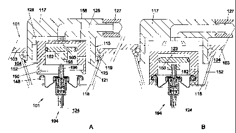
In Fig. 3A, a portion of the wall 103 of a container
101 is shown, with an opening 115 therein, in which a movable
closing means 117 is received, in sealing engagement with a
rubber ring 119 or like sealing element. At some distance
below the opening 115, by means of suitable suspension means
121, the first housing 118 of the pressure control device 108
is suspended such that the pressure control device 108 is
CA 02355262 2001-06-13
WO 00/35774 PCT/NL99/00771
16
mounted in a positionally fixed manner. In the closing means
117, on the side proximal to the first chamber 124, a space
123 is recessed, in which the second housing 152 can be
secured with a slightly clamping fit, such that the counter-
coupling means 150 extend at a slight distance from the
further coupling means 148. The axial bore 198 is then
likewise located at a slight distance from the rod-shaped
element 196. In this position, the valve 194 cannot be
energized, at least cannot be opened, so that no gas can flow
from the first chamber 124 to the inner space 104.
In the closing means 117, a discharge channel 125 is
included, which at one end is connected to the cavity 123 and
at the other end can be connected to, for instance, a hose
127 which can be connected to a tapping device or the like.
In the cavity, a series of ribs 128 are provided, which keep
the end wall 156 of the second housing 152 spaced from the
walls of the cavity 123, both in axial and in radial
direction. Accordingly, during use, beverage 2 can flow past
the second housing 152 to the discharge channel 125,
regardless of the position of the closing means 117.
To make the pressure control device 101 ready for
use, in a container 101 according to Fig. 3 only the closing
means 117 needs to be moved in the direction of the inner
space 104, thereby pressing the second housing 152 fixedly
onto the first housing 118 by means of the coupling means
148, 150. At the same time, the axial bore 198 is thereby
pushed over the rod-shaped element 196. This ready-for-use
CA 02355262 2001-06-13
WO 00/35774 PCT/NL99/00771
17
condition is shown in Fig. 3B. The closing means 117 can then
be moved back upwards, but can optionally be secured in the
depressed position. In the condition shown in Fig. 3B, the
pressure in the inner space 104 will be controlled depending
on the control pressure in the second chamber 160 and the
pressure in the third chamber 162, in the manner described
hereinbefore.
In a variant, not shown, of the embodiment according
to Fig. 3, the closing means 117 comprises a valve which
closes the discharge channel 125 in the condition shown in
Figs. 3A and 3B, i.e., the extreme upwardly moved condition.
This valve is automatically opened when the closing means 117
in Fig. 3A or B is pushed down. The advantage thereby
achieved is that the closing means 117 can at the.same time
function as tap 116. The discharge channel 125, however, can
also be omitted when another tap is provided, for instance as
shown in Fig. 1.
Also, in an embodiment as shown in Fig. 3, the piston
can be connected with the rod-shaped element 196, such that
prior to activation the chamber 160 is relatively large, and
is reduced only when the closing means 117 is pressed down.
Fig. 4 shows an alternative embodiment, in which the
housing 252 for the second chamber 260 is connected with the
valve 294, while the piston 258 extends into the open end of
the housing 252 remote from the first chamber 224 and can be
secured in two positions with respect to the wall 203 of the
container. In Fig. 4, on the left-hand side, the piston 258
CA 02355262 2001-06-13
WO 00/35774 PCT/NL99/00771
18
is secured in an upper position, so that the second chamber
260 is relatively large and substantially pressureless, such
that the housing 252 will remain stationary. By pressing the
piston 258 down into the position shown on the right-hand
side in Fig. 4, in which it is retained on the wall 203 by
means of fingers 253, the volume of the second chamber 260 is
reduced considerably, so that a desired control pressure is
obtained therein. A change of the pressure in the inner space
204 to a value below the control pressure will presently
result in the housing 252 moving away from the piston 258, in
downward direction, thereby operating the valve 294 for
release of gas from the first chamber 224.
Fig. 5 shows an embodiment of a control device
according to the invention in which a first chamber 324 is
equipped with a valve 394, being a male valve in the
embodiment shown. It will be clear, however, that this may
also be a female or tilting valve. A second chamber 360 is
provided in a housing 352, in which a piston 358 is received
with a proper fit, along with a sealing 0-ring 370. A stem
366 is fixedly connected with the piston 358 and extends in
the direction of the valve 394. The free end 367 of the stem
366 is clear of the valve 394. A substantially cylindrical
intermediate part 396 has a first end secured on the valve
394 and has its circumferential wall provided with a number
of passage openings 397 for forming a fluid connection
between the first chamber 324 and the third chamber 304 when
the valve is opened. The intermediate part 396 is provided,
CA 02355262 2001-06-13
WO 00/35774 PCT/NL99/00771
19
adjacent the open second end remote from the first chamber,
with a widened portion 371 with a shoulder 373. The free end
367 of the stem 366 extends into the bore 375 of the
intermediate part 369 and is provided with outwardly biased
resilient fingers 377. In the first position shown in Fig. 5,
the fingers 377 rest against the inside of the narrower
portion of the bore 375, between the valve 394 and the
shoulder 373. This means that the piston 358 can move freely
over a pre-selected distance, which distance is determined,
on the one hand, by the minimum distance between the free end
367 and the valve 394 and, on the other hand, by the position
of the fingers 377 and the shoulder 373. In fact, when the
piston 358 is moved further within the housing 352 in the
direction of the end wall 356, as far as or beyond the
position represented in broken lines, the free ends of the
fingers 377 end up above the shoulder 373 and will spring
outwardly, such that upon subsequent downward movement of the
piston 358, they will engage the top surface of the shoulder
373. The fingers 377 and the shoulder 373 thus form first and
second coupling means. When the piston 358 is moved down from
the position represented in broken lines, then, as a result
of an increase of the volume of the second chamber 360, the
intermediate part 369 will be moved down along with it and
the valve 394 will thereby be opened.
From the position of the piston 3"58 shown in solid
lines in Fig. 5, which does not permit operation of the valve
394, it can be brought into a position of use by an
CA 02355262 2001-06-13
WO 00/35774 PCT/NL99/00771
activation step. To that end, for instance, the pressure in
the third chamber 304 is temporarily raised from outside,
such that the piston 358 is moved up to the position
represented in broken lines, whereby the control pressure in
5 the second chamber 360 is at least approximated. As a result,
the fingers 377 are moved to above the shoulder 373, and the
active position of use is achieved. It will be clear that
this can also be achieved, for instance, by mechanically
pulling the piston 358 up into the position represented in
10 broken lines, or in any other suitable manner.
Fig. 6 schematically shows an alternative embodiment,
where in the stem 466 the bore 475 is provided, which stem
466 is connected with the piston 458, such that the bore 475
has a blind end 479. Adjacent the open end 481, the bore 475
15 is provided with a widened portion 471, such that a shoulder
473 is formed at a distance from the blind end 479. An
intermediate part 469 has a first end secured in a valve 494,
female in this example, and is provided with a passage 497
for forming a fluid connection between the first chamber 424
20 and the inner space 404 of the container when the valve is
open. The intermediate part 469 is provided with outwardly
biased resilient fingers 477. When the free ends of the
fingers 477 are pinched together, they can be slipped into
the relatively narrow portion of the bore 475 between the
blind end 479 and the shoulder 473, where the fingers 477 can
move~freely in the longitudinal direction, so that movements
of the piston 458 are permitted without the valve 494 being
CA 02355262 2001-06-13
WO 00/35774 PCT/NL99/00771
21
operated. Only when the piston is moved such that the volume
of the chamber 460 is reduced considerably and the free ends
483 of the fingers 477 are moved to below the shoulder 473
can the fingers 477 expand such that the free ends 483 can
engage the shoulder 473. In this position, a movement of the
piston 458 in the direction of the valve 494 results in the
intermediate part 469 being pressed down along with it,
thereby.opening the valve 494. The first and second position
of the first and second coupling means formed by the stem
466, at least the shoulder 473, and the intermediate part
469, at least the fingers 477, are represented in broken
lines in the first, uncoupled position and second, coupled
position.
Fig. 7 shows a portion of a control means according
X5 to Fig. 6, where the piston 458 has a stem 466 which is
divided into two parts 466A, 466B. The first, cylindrical
part 466A is fixedly connected with the piston 458 and is
provided at the free end with an inwardly extending flange
461 with an opening. Through the opening extends the second
part 466B of the stem 466, which is provided, at the end
located within the first stem part 466A, with a widening
which provides for proper guidance and moreover butts against
the flange 461 when the second stem part 466B has been moved
down maximally. In the second stem part 466B, a bore 475 is
provided having a widening 471 adjacent the outer free end,
thereby forming a shoulder 473. The fingers 477, not shown in
Fig. 7, of the intermediate part 469 as shown in Fig. 6 can
CA 02355262 2001-06-13
WO 00/35774 PCT/NL99/00771
22
again be received in the bore 475 in the first and second
position referred to. In this embodiment, the advantage
achieved is that the piston 458 acquires a greater free
movement with the coupling means 477, 473 in the first
position, disallowing operation of the valve 494, since the
second stem part 466B can move freely relative to the first
stem part 466A over the distance S. Only when the inner end
of the second stem part 466B rests against the piston 458A
and the fingers 477 rest against the shoulder 473 can the
valve 494 be operated.
--Fig_.-8 shows a further alternative embodiment of a
piston 458 with stem 466 for use in a pressure control device
according to Fig. 6. In the widened portion 471 of the bore
475, a ridge 485 extends from the shoulder 473 in the
direction away from the piston 458 and the blind end 479 of
the bore 475, which ridge 485 is included within the widened
portion 471. In this embodiment, the free ends 483 of the
fingers 477 will have to pass the edge 487 of the ridge 485
in order to be brought from the first, uncoupled position to
the second, coupled position to be able to rest against the
shoulder 473. The advantage thereby achieved is that the
piston 458 will have to be moved relative to the housing 425
over a relatively great distance, i.e., the volume of the
second chamber 460 will have to be reduced considerably,
clearly further than is necessary for the desired control
pressure. This means that the chance of undesired activation
is reduced considerably, which enhances safety still further.
CA 02355262 2001-06-13
WO 00/35774 PCT/NL99/00771
23
Figs. 9 and 9A show, in cutaway side elevation and
partial front view, a further alternative embodiment of
control means for a container according to the present
invention. In this embodiment, on the valve 594 of the first
chamber 524, an intermediate part 569 with passage 597 is
secured, on which intermediate part a resilient finger 577 is
mounted. In the position shown in Fig. 9, the resilient
finger 577 is optionally biased to the left, for reasons to
be described further hereinafter. Attached to the piston 558
with piston ring 570 is a stem 566, provided with two bores
located.. next to each other. In Fig... _9, the. first bore 575A,
located on the left-hand side, has a depth S1, the second
bore 575B, located on the right-hand side, has a depth SZ,
which is greater than depth S1. The depth has been determined
starting from the open end 581 of the bores 575, remote from
the piston 558. The resilient finger 577 is provided, at the
free end, with a head 591, designed as a cross-stick in the
embodiment shown. The first bore 575A is separated from the
second bore 575B by a partition 595 which terminates at a
distance from the open end 581. Adjacent to the open end 581
of the bore, a somewhat flexible flap 593 is connected on the
side of the first bore 575A and extends at a slant up against
the opposite wall of the second bore 575B. Provided in the
flap 593 is a slot 593A through which the finger 577 can
extend. The head 591 then rests against the side of the
prongs of the fork-shaped flap 593 proximal to the
piston 558.
CA 02355262 2001-06-13
WO 00/35774 PCT/NL99/00771
24
In Fig. 9, the first, uncoupled position is shown, in
which the head 591 extends in the second bore 575B, between
the blind end thereof and the flap 593. The piston 558 can
then move freely over a height which is determined by the
distance between the free edge 599 of the partition 595 and
the blind end 579B of the second bore 575B. When the piston
558 is moved upwards so far that the head 591 extends under
the free edge 599, it will be guided into the first bore 575A
by the flap 593. If subsequently the piston 558 is moved down
again, the head 591 will be received in the first bore 575A
and butt against the blind end 579A of the first bore 575A,
so that the coupled second position is obtained. Upon further
downward movement of the piston 558, the valve 594 will be
operated via the finger 577. The flap 593 prevents the
possibility of the head 591 being released from the bore 575.
Moreover, the flap 593 is located so close to the edge 599 of
the partition 595 that the head 591 will not be easily moved
between them when the head moves up along the flap 593. The
head 591 is thereby prevented from moving back into the
second bore 575B. It is noted, incidentally, that when the
finger 579 is sufficiently biased in the direction of the
first bore 575A, the flap 593 can optionally be omitted.
Figs. 10 and 10A show in partial sectional side
elevation and in perspective view, respectively, a further
alternative embodiment of an operating device according to
the invention, suitable in particular for use with a tilting
valve. Such tilting valves, by which a passage opening can be
CA 02355262 2001-06-13
WO 00/35774 PCT/NL99/00771
opened or closed by tilting an operating stem, are known from
practice and are not further discussed here. In this
embodiment, the tilting valve 694, connected with the first
chamber 624, is provided with an operating stem 669 with a
5 widened head 667. The head 667 has a preferably convex top.
In the housing 652 of the second chamber 660, a piston 658 is
received, on which a stem 666 has been secured. The piston
658 has a direction of travel P, which extends at an angle,
and preferably at right angles, relative to the centerline L
10 of the tilting valve 694 and the operating stem 669. The stem
666 of the piston 658 is provided with a first fork 690 and a
second fork 692. In Fig. 10A, in perspective view, the stem
666 with the first fork 690 and the second fork 692 is
represented, together with the operating stem 669 with its
15 widened head 667. The first and second forks 690, 692 are
located in parallel planes, at some distance from each other.
In the neutral position shown in Fig. 10A, this distance is
indicated by D'1. Each fork 690, 692 comprises two prongs with
an intervening slot 690A and 690B, respectively, which slots
20 are open at the end remote from the piston 658. The slots
690A, B have a width greater than the thickness of the
operating stem 669, but smaller than the width of the head
667. Accordingly, the two forks 690, 692 can be slipped
between the valve 694 and the head 667 over the operating
25 stem 669. The first fork 690 is shorter than the second fork
692, as are the slots provided therein. The closed end 679A
of the first slot 690A lies at a distance from the piston 658
CA 02355262 2001-06-13
WO 00/35774 PCT/NL99/00771
26
greater than the distance between the piston and the closed
end 679B of the second slot 690B.
In Fig. 10, in the upper portion, the operating
device is shown in an uncoupled first position, where the
first fork 690, elastically deformed to some extent, rests
against the top of the knob 667. The materials and the
deformation of the fork have been selected such that the
movement of the piston 658 in the direction P is possible
without the operating stem 669 thereby being carried along.
From this position, the device can be activated by displacing
the piston 658 in the direction of the_end wall 656, such
that the free end of the first fork 690 can pass the head
667. Elastic deformation stress in the first fork 690 will
then ensure that it returns to the plane V, such that it will
extend under the underside of the head 667. As a result, upon
return of the piston 658 in the direction of the valve 694,
the operating stem 669 will be received in the first slot
690A. Upon further movement of the piston 658 in the
direction away from the end wall 656, upon increase of the
volume of the chamber 660, the blind end 679A will butt
against the operating stem 669 and, upon further movement,
carry along the operating stem 669, so that it is tilted
relative to the longitudinal axis L referred to above. The
tilting valve 694 will thereby be opened, and gas can flow
from the first chamber 624 to the inner space 604. Upon
increase of the pressure in the inner space 604, the piston
658 will move back, the second chamber 660 thereby being
CA 02355262 2001-06-13
WO 00/35774 PCT/NL99/00771
27
reduced, so that the tilting valve 694 can return to its
closed position. Optionally, on the operating stem 669,
between the valve 624 and the head 667, a guide ring 667A can
be provided, represented in Fig. 10 in broken lines, such
that at least the second fork 692 is guided between the valve
694 and the guide ring 667A, so that a still better
positioning is obtained.
Fig. 11 shows a simple embodiment of a device
according to the present invention for operating a tilting
valve 794. In this embodiment, the piston 758, which bounds
the.second chamber 760 within the housing 752, comprises a
stem 766 with a beveled free end 781. On the tilting valve
794 on the first chamber 724, a coupling part 769 is provided
with a likewise beveled free end 783. The stem 766 is guided
within the housing 752 by a guide 757. Upon enlargement of
the second chamber 760 the stem 766 is moved down, in the
direction of the tilting valve 794. The cooperating beveled
ends 781, 783 will ensure that the tilting valve 794 is
tilted from the closed position to an open position. Such a
solution can also be readily utilized in exemplary
embodiments shown hereinabove when tilting valves are used
instead of valves or operating means shown there.
Fig. 12 shows a further alternative embodiment of a
pressure control device 808 according to the invention. In
this embodiment, in a recess 872 in the first housing 818, a
passage opening 828 is provided, with an axial bore 836. A
closing member 840 in the form of a ball is urged against the
CA 02355262 2001-06-13
WO 00/35774 PCT/NL99/00771
28
seating 834 by biasing means 842, with a pin 880 extending
from the closing member 840 through the axial bore 836 into
the recess 872. The biasing means 842 and the closing member
840 are received in a fourth chamber 886 with inflow openings
888 terminating in the first chamber 824. As a consequence,
the recess 872 can be located at a relatively great distance
from the wall of the first housing 818. In this embodiment,
the second housing 852 is accommodated in the recess 872,
such that it has the end wall 856 resting on the bottom 878
of the recess. In this embodiment, the piston 858 is designed
as a.cyl.inder with an outer circumference_approximately
corresponding with the inner circumference of the second
housing 852, with interposition of a fitting piston ring 870
or like gas-tight and liquid-tight sealing means. Between the
piston 858 and the end wall 856, again the second chamber 860
is formed. At the end of the piston 858 remote from the
second chamber 860, a control means 866 is included, designed
as a disc 867 with frustoconical edges 890, 892. This disc
867 has an outside diameter which, for instance, corresponds
approximately with the inside diameter of the recess 872,
while the smallest diameter of the frustoconical edges 890,
892 is approximately equal to the diameter of the piston 858.
With the piston 858 in a neutral position, i.e., in
an uncoupled position, with a low pressure prevailing in the
second chamber 860, the lower conical edge 892 is disposed
against the upper side of the pin 880. Accordingly, the
closing member 840 cannot be operated by the piston 858,
CA 02355262 2001-06-13
WO 00/35774 PCT/NL99/00771
29
since it is pushed outwards by the spring 842. When in the
third chamber 862 at least temporarily the pressure is raised
considerably, the piston 858 will be pushed downwards,
thereby reducing the second chamber 860 and raising the
pressure therein. The piston 858 will then be pushed past the
pin 880, temporarily pressing it away, counter to the spring
842. After the piston 858 has passed, the closing member 840
will be pushed back into the closing position. Thus, the
control device 808 is activated. When the pressure in the
third chamber 862 decreases again to below the control
pressure, the piston 858 will be pushed away upwardly,
thereby pushing away the pin 880 and hence the closing member
840, counter to the spring 842, thereby forming a fluid
connection between the first chamber 824, the opening'888,
the fourth chamber 886 and the outflow opening 828, for
raising the pressure in the third chamber 862 and hence in
the inner space of the container. When the pressure in the
inner space has been raised again sufficiently, the piston
858 will be pushed back again into the position shown in
Fig. 12, and the closing member is closed again.
In principle, operating devices according to the
present invention have as an important additional advantage
that upon fall-out of the control pressure in the second
chamber, for instance through leakage, the operating means is
forced to a closed position,,so that gas is simply and
effectively prevented from uncontrollably flowing from the
first chamber to the third chamber and giving rise to
CA 02355262 2001-06-13
WO 00/35774 PCT/NL99/00771
excessive pressure in the container, at least in the third
chamber. Thus, the safety of a container according to the
present invention, at least of a pressure control device to
be used therein, is enhanced still further.