Sélection de la langue

Search

Sommaire du brevet 2355430 

Énoncé de désistement de responsabilité concernant l'information provenant de tiers

Une partie des informations de ce site Web a été fournie par des sources externes. Le gouvernement du Canada n'assume aucune responsabilité concernant la précision, l'actualité ou la fiabilité des informations fournies par les sources externes. Les utilisateurs qui désirent employer cette information devraient consulter directement la source des informations. Le contenu fourni par les sources externes n'est pas assujetti aux exigences sur les langues officielles, la protection des renseignements personnels et l'accessibilité.

Disponibilité de l'Abrégé et des Revendications

L'apparition de différences dans le texte et l'image des Revendications et de l'Abrégé dépend du moment auquel le document est publié. Les textes des Revendications et de l'Abrégé sont affichés :

  • lorsque la demande peut être examinée par le public;
  • lorsque le brevet est émis (délivrance).
(12) Brevet: (11) CA 2355430
(54) Titre français: VERIFICATEUR MECANIQUE DE PIECES DE MONNAIE
(54) Titre anglais: MECHANICAL COIN CHECKER
Statut: Périmé et au-delà du délai pour l’annulation
Données bibliographiques
(51) Classification internationale des brevets (CIB):
  • G07D 5/00 (2006.01)
  • G07D 5/02 (2006.01)
  • G07F 1/04 (2006.01)
(72) Inventeurs :
  • TRENNER, DIETMAR (Allemagne)
(73) Titulaires :
  • WALTER HANKE MECHANISCHE WERKSTATTEN GMBH & CO. KG
(71) Demandeurs :
  • WALTER HANKE MECHANISCHE WERKSTATTEN GMBH & CO. KG (Allemagne)
(74) Agent: OSLER, HOSKIN & HARCOURT LLP
(74) Co-agent:
(45) Délivré: 2007-07-03
(22) Date de dépôt: 2001-08-16
(41) Mise à la disponibilité du public: 2002-02-17
Requête d'examen: 2003-09-24
Licence disponible: S.O.
Cédé au domaine public: S.O.
(25) Langue des documents déposés: Anglais

Traité de coopération en matière de brevets (PCT): Non

(30) Données de priorité de la demande:
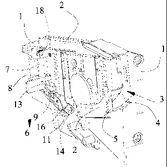
Numéro de la demande Pays / territoire Date
100 42 167.9 (Allemagne) 2000-08-17

Abrégés

Abrégé anglais


Abstract:
A mechanical coin checker is proposed having a coin
channel which has a running rail for the coin to run
down, in or at which channel checking arrangements
are provided to check the properties of the coins,
having a coin acceptance shaft and a return shaft,
disposed below the running rail, to return coins
which are not accepted. The running rail has in the
running direction of the coin a recess into which
coins which are too thin slide and possibly fall into
the return shaft. In front of the coin acceptance
shaft is disposed a detent pawl, which is rotatably
mounted at a flap forming a part of the coin channel.
A detent wire, which is pivotable about a portion of
its longitudinal axis, co-operates with its one end
region with the detent pawl and is disposed with its
other end region below the recess, in such a way that
when a coin slips through the recess, the detent wire
pivots and takes the detent pawl with it into the
coin channel to engage at least one integrally formed
arm.

Revendications

Note : Les revendications sont présentées dans la langue officielle dans laquelle elles ont été soumises.


THE EMBODIMENTS OF THE INVENTION IN WHICH AN EXCLUSIVE
PROPERTY OR PRIVILEGE IS CLAIMED ARE DEFINED AS FOLLOWS:
1. A mechanical coin checker having a coin channel which
has a running rail for a coin to run down, in or at
which channel checking arrangements are provided to
check properties of coins, having a coin acceptance
shaft and a return shaft, disposed below the running
rail, to return coins which are not accepted, the
running rail having in a running direction of the coin
a recess into which coins which are too thin slide
wherein
a detent pawl is disposed in front of the coin
acceptance shaft, said detent pawl is rotatably mounted
at a flap forming a part of the coin channel; and a
detent wire is pivotable about a portion of its
longitudinal axis and cooperates with its one end
region with the detent pawl and is disposed with its
other end region below the recess, in such a way that
when a coin slips through the recess, the detent wire
pivots and takes the detent pawl with it into the coin
channel to engage at least one integrally formed arm.
2. The mechanical coin checker according to claim 1,
wherein the detent wire is rotatably mounted with its
central region in a longitudinal grooves, and the one
end region is bent at an oblique angle away from the
central region, and the other end region is bent in a
U-shape.
3. The mechanical coin checker according to claim 2,
wherein the detent wire is so mounted in a rest state
that a portion of the U-shaped end region stands up at

11
an oblique angle towards the recess and the detent wire
forms a rocker, in such a way that when a coin hits the
U-shaped end region, the obliquely-angled end region
pivots and comes into contact with the arm of the
detent pawl.
The mechanical coin checker according to claim 2,
wherein the longitudinal groove is formed in the flap
and is covered by a plate.
The mechanical coin checker according to claim 1,
wherein the flap can be pivoted from outside via a
control button and a running slope, the arm of the
detent pawl engaging in the coin channel.
The mechanical coin checker according to claim 1,
wherein the detent pawl is an L-shaped flat metal strip
and the arm is bent several times in a stepped manner
at an angle.
The mechanical coin checker according to claim 6,
wherein said arm is bent at an angle of 90°.

Description

Note : Les descriptions sont présentées dans la langue officielle dans laquelle elles ont été soumises.


CA 02355430 2001-08-16
3
Mechanical coin checker
BACKGROUND OF THE INVENTION
1. Field of t'he Invention
The invention relates to a mechanical coin checker
used in coin operated machines like washing machines,
coin operated gaming machines, automatic ending ma-
chines and the like.
2. Description of the prior art
A large number of mechanical coin checkers are known
in prior art which have in the region of their coin
running channel, which joins onto the coin slot, a
sensor arrangi=_ment which checks whether the coin is
genuine and admissible. The sensors check e.g. the
dimensions of the coin, and where the mechanical di-

CA 02355430 2005-08-24
4
mensions of the coin to be checked are identical, they have
to be distinguished by means of their metallic properties.
Magnetic checking arrangements are known for this purpose.
To check the dimensions, there are limitations formed by
rails or the like which take into account the diameter or
the thickness of the coin. The coin channel has for example
a lower running rail down which the coin runs, being
supported with its upper edge against a rail. If the coin
is too small it falls through below the rail and reaches a
return channel. A recess is incorporated in the lower
running rail in the longitudinal direction, such that a coin
which is too thin slips into this recess and then falls into
the return channel. However, it sometimes happens that the
coin becomes stuck in the recess and it has been shown that
in this case there has been manipulation from the outside so
that when a non-admissible, too thin coin or disc is
inserted, which slides into the recess of the running rail,
from outside a wire or a strip of cardboard or the like is
inserted into the coin channel, with which implement the
coin or disc which has become stuck is pushed forward so
that it reaches the acceptance channel or the
acknowledgement region.
SUMMARY OF THE INVENTION
A feature of one embodiment of the present invention, is to
improve the mechanical coin checker and to make available an
additional measure which prevents passing a non-admissible
coin into the acknowledgement region. Another feature of a
preferred embodiment is to prevent one type of manipulation
realized by pushing a coin in the coin channel from outside
by means of a tool into the acceptance channel.
According to the present invention the mechanical

CA 02355430 2001-08-16
coin checker has a coin channel which has a running
rail for the coin to run down, in or at which channel
checking arrangements are provided to check the prop-
erties of coins, having a coin acceptance shaft and a
5 return shaft, disposed below the running rail, to re-
turn coins which are not accepted, the running rail
having in the running direction of the coin a recess
into which coins which are too thin slide and possi-
bly fall into the return shaft, wherein in front of
the acceptance shaft a detent pawl is disposed which
is rotatably mounted on a flap forming a part of the
coin channel, and because a detent wire, pivotable
about a portion of its longitudinal axis, co-operates
with its one end region with the detent pawl, and
with its other, bent end region is disposed below the
recess, in such a way that when a coin slips through
the recess, the detent wire, as a result of the
weight of the coin acting on the bent end region,
pivots about the longitudinal axis, and thus the
other end of t]ae detent wire comes into contact with
the detent pawl and swivels the latter in the direc-
tion of the coin channel, whereby an arm engages in
the coin channel. Thus the coin channel is blocked
towards the acknowledgement region, such that even by
manipulation f:rom outside through the coin slot by
means of a tool, such as a strip of cardboard or the
like, the coin cannot be pushed into the acceptance
channel.
BRIEF DESCRIPTION OF THE DRAWINGS
An embodiment of the invention is represented in the
drawing and is explained in greater detail in the
following description showing other objects and ad-
vantages.

CA 02355430 2001-08-16
6
The figures show:
Fig. 1 a perspective view of a mechanical coin
chec}cer according to the invention, with an
insei-ted coin, in which a portion of the
coversng flap has been omitted for better
recoqnition,
Fig. 2 a view of the coin checker according to
Fig. 1 from another perspective, wherein
again a portion of the flap and the basic
body have been omitted for better recogni-
tion,.
Fig. 3 a sectional view through the bearing point
of the detent wire, and
Fig. 4 a perspective view of a coin checker ac-
cording to Fig. 1 and Fig. 2, in which the
coin has actuated the detent wire.
DETAILED DESCR:LPTION OF THE PREFERRED EMBODIMENT
The mechanical coin checker represented in Fig. 1 has
a basic body 1, on which a flap 2 is secured so as to
be pivotable; in the embodiment shown, the flap 2 is
shown open for a better view in the central region,
so that the invention can be better recognised. To
the basic body are secured a plurality of checking
elements, not shown, for example magnets and the
like. From the outside a coin channel is accessible
via a coin slot, not shown, in direction 3, the coin
entry channel n.aving a running rail 4 connected to
the basic body 1, and being delimited laterally by
the basic body and by the flap 2 or respectively by
elements which are secured to both parts. The flap 2

CA 02355430 2001-08-16
-1
can be pivoted from outside by means of a control
button which i" connected to a pin or the like slid-
ing along a sloping surface 5. The coin channel
opens out into a coin acceptance channel for admissi-
ble and recognised coins, which channel is indicated
by arrow 6 and into which fall the coins which have
been recogniseci as admissible coins by the various
checking devices. Below and to the side of the run-
ning rail 4 is provided a return channel, not shown,
which is delimited in the lower region of Fig. 1 by a
cover, and which leads non-admissible or unrecognised
coins towards the outside.
At the flap 2, in front of the coin acceptance chan-
nel, a detent pawl 7 is rotatably mounted, which com-
prises a flat L-shaped metal strip with two inte-
grally formed arms 8, 9, both arms pivoting into the
coin channel when the flap 2 is opened via the slop-
ing surface 5. Here the one arm 8 lies in the plane
of the strip whilst the other arm 9 is bent away at
least twice, preferably however 3 times, at an angle
of 90 .
The running rail 4 itself serves together with the
abutting flap ? as a sensor for detecting coins or
discs which aria thinner than the admissible coins.
To this end thi_re is provided in the running direc-
tion of a coin in the lower running rail, at the
side, a recess 10 which can be recognised in outline
in Fig. 2. In the case of a coin which is too thin,
the latter slides through the recess 10 and becomes
stuck or falls into the return shaft lying below the
recess. As an additional measure for actuating the
detent pawl 7 and to prevent manipulation, a detent
wire 11 is rotatably mounted at the flap 2. The de-
tent wire 11 comprises three portions, a central por-

CA 02355430 2001-08-16
8
tion 12 which serves to mount it, and two end por-
tions 13, 14. As can be recognised from Fig. 3,
there is worked out of the flap 2 a longitudinal
groove 15 into which the central section 12 of the
detent wire 11 is inserted and which is covered by a
cover plate 16 securely connected to the flap 2, for
example by riviceting. The central portion 12 of the
detent wire 11 is mounted in this groove 15 so as to
be rotatable or pivotable about its longitudinal
axis. The one end portion 13 is bent away obliquely
upwards from t;Iie central portion 12 and the other end
portion 14 is shaped into a U-shape. The coin
checker when fitted is slightly inclined and the di-
mensions of the length of the end portion 13 take
into account its gravity in such a way that the de-
tent wire remains in stable in the rest state.
The detent wirie 11 is inserted in the groove 15 in
its rest position, which can be best recognised from
Fig. 2,. in such a way that the bent-up end portion 13
is opposite the arm 9 without influencing same, and
that the other U-shaped end portion 14 is directed
obliquely upwards, such that at least one mernber of
the U-shape lies below the recess 10 or dips slightly
into the latter. Thus the detent wire forms a
rocker.
When a coin is introduced into the coin channel in
coin entry direction 3, as a result of the inclined
arrangement of the running rail 4 it rolls in an in-
clined position along the coin channel, and when the
coin 17, as indicated in Figs. 2 and 4, is too thin,
it slips through the recess 10. Usually it becomes
stuck there and could be pushed further with a long
thin object which can be inserted from outside. How-
ever, as can be recognised in Fig. 4, this is pre-

CA 02355430 2001-08-16
9
vented by the detent pawl 7. Through its weight
namely the coin 17 presses on the U-shaped end por-
tion 14 and pushes the latter downwards according to
Fig. 2, by which means the central portion 12 rotates
about its longitudinal axis and the bent-away end
portion comes into contact with the arm 9 of the de-
tent pawl, whereby the whole detent pawl pivots to
the right in Fig. 2 about the bearing 18 of the de-
tent pawl 7. This can be recognised in Fig. 4, i.e.
the detent wire or the end portion 13 locks the de-
tent pawl 7 in a position in which the arms 8, 9 en-
gage in the coin channel, until the coin 17 presses
on the U-shaped end portion 14. The coin 17 can now
only be freed by the flap 2 being opened via the
sloping surface 5 and the jammed coin 17 falling into
the return shaft. Thereafter the detent wire 11 piv-
ots back with the support of the detent pawl 7.

Dessin représentatif
Une figure unique qui représente un dessin illustrant l'invention.
États administratifs

2024-08-01 : Dans le cadre de la transition vers les Brevets de nouvelle génération (BNG), la base de données sur les brevets canadiens (BDBC) contient désormais un Historique d'événement plus détaillé, qui reproduit le Journal des événements de notre nouvelle solution interne.

Veuillez noter que les événements débutant par « Inactive : » se réfèrent à des événements qui ne sont plus utilisés dans notre nouvelle solution interne.

Pour une meilleure compréhension de l'état de la demande ou brevet qui figure sur cette page, la rubrique Mise en garde , et les descriptions de Brevet , Historique d'événement , Taxes périodiques et Historique des paiements devraient être consultées.

Historique d'événement

Description Date
Inactive : Regroupement d'agents 2013-10-24
Le délai pour l'annulation est expiré 2011-08-16
Lettre envoyée 2010-08-16
Accordé par délivrance 2007-07-03
Inactive : Page couverture publiée 2007-07-02
Préoctroi 2007-04-12
Inactive : Taxe finale reçue 2007-04-12
Un avis d'acceptation est envoyé 2006-10-31
Lettre envoyée 2006-10-31
Un avis d'acceptation est envoyé 2006-10-31
Inactive : Approuvée aux fins d'acceptation (AFA) 2006-06-17
Inactive : CIB de MCD 2006-03-12
Modification reçue - modification volontaire 2005-08-24
Inactive : Dem. de l'examinateur par.30(2) Règles 2005-02-24
Inactive : Dem. de l'examinateur art.29 Règles 2005-02-24
Lettre envoyée 2003-10-14
Exigences pour une requête d'examen - jugée conforme 2003-09-24
Toutes les exigences pour l'examen - jugée conforme 2003-09-24
Requête d'examen reçue 2003-09-24
Lettre envoyée 2003-08-26
Demande publiée (accessible au public) 2002-02-17
Inactive : Page couverture publiée 2002-02-17
Lettre envoyée 2001-10-31
Modification reçue - modification volontaire 2001-10-22
Inactive : CIB en 1re position 2001-09-25
Inactive : Transfert individuel 2001-09-20
Inactive : Lettre de courtoisie - Preuve 2001-09-11
Inactive : Certificat de dépôt - Sans RE (Anglais) 2001-09-05
Exigences de dépôt - jugé conforme 2001-09-05
Demande reçue - nationale ordinaire 2001-09-05

Historique d'abandonnement

Il n'y a pas d'historique d'abandonnement

Taxes périodiques

Le dernier paiement a été reçu le 2006-07-28

Avis : Si le paiement en totalité n'a pas été reçu au plus tard à la date indiquée, une taxe supplémentaire peut être imposée, soit une des taxes suivantes :

  • taxe de rétablissement ;
  • taxe pour paiement en souffrance ; ou
  • taxe additionnelle pour le renversement d'une péremption réputée.

Veuillez vous référer à la page web des taxes sur les brevets de l'OPIC pour voir tous les montants actuels des taxes.

Historique des taxes

Type de taxes Anniversaire Échéance Date payée
Taxe pour le dépôt - petite 2001-08-16
Enregistrement d'un document 2001-09-20
Enregistrement d'un document 2003-07-23
TM (demande, 2e anniv.) - petite 02 2003-08-18 2003-07-31
Requête d'examen - petite 2003-09-24
TM (demande, 3e anniv.) - petite 03 2004-08-16 2004-08-16
TM (demande, 4e anniv.) - petite 04 2005-08-16 2005-07-28
TM (demande, 5e anniv.) - petite 05 2006-08-16 2006-07-28
2006-07-28
Pages excédentaires (taxe finale) 2007-04-12
Taxe finale - petite 2007-04-12
TM (brevet, 6e anniv.) - générale 2007-08-16 2007-08-03
TM (brevet, 7e anniv.) - générale 2008-08-18 2008-08-04
TM (brevet, 8e anniv.) - générale 2009-08-17 2009-07-30
Titulaires au dossier

Les titulaires actuels et antérieures au dossier sont affichés en ordre alphabétique.

Titulaires actuels au dossier
WALTER HANKE MECHANISCHE WERKSTATTEN GMBH & CO. KG
Titulaires antérieures au dossier
DIETMAR TRENNER
Les propriétaires antérieurs qui ne figurent pas dans la liste des « Propriétaires au dossier » apparaîtront dans d'autres documents au dossier.
Documents

Pour visionner les fichiers sélectionnés, entrer le code reCAPTCHA :


Pour visualiser une image, cliquer sur un lien dans la colonne description du document. Pour télécharger l'image (les images), cliquer l'une ou plusieurs cases à cocher dans la première colonne et ensuite cliquer sur le bouton "Télécharger sélection en format PDF (archive Zip)" ou le bouton "Télécharger sélection (en un fichier PDF fusionné)".

Liste des documents de brevet publiés et non publiés sur la BDBC .

Si vous avez des difficultés à accéder au contenu, veuillez communiquer avec le Centre de services à la clientèle au 1-866-997-1936, ou envoyer un courriel au Centre de service à la clientèle de l'OPIC.


Description du
Document 
Date
(aaaa-mm-jj) 
Nombre de pages   Taille de l'image (Ko) 
Dessin représentatif 2002-01-17 1 14
Page couverture 2002-02-08 2 51
Dessins 2001-08-16 3 55
Abrégé 2001-08-16 1 27
Description 2001-08-16 7 244
Revendications 2001-08-16 2 59
Revendications 2005-08-24 2 55
Description 2005-08-24 7 241
Dessins 2001-10-22 3 57
Dessin représentatif 2007-06-15 1 16
Page couverture 2007-06-15 1 48
Certificat de dépôt (anglais) 2001-09-05 1 175
Courtoisie - Certificat d'enregistrement (document(s) connexe(s)) 2001-10-31 1 113
Rappel de taxe de maintien due 2003-04-17 1 107
Accusé de réception de la requête d'examen 2003-10-14 1 173
Avis du commissaire - Demande jugée acceptable 2006-10-31 1 161
Avis concernant la taxe de maintien 2010-09-27 1 170
Correspondance 2001-09-05 1 24
Taxes 2003-07-31 1 51
Taxes 2004-08-16 1 103
Taxes 2005-07-28 1 50
Taxes 2006-07-28 1 48
Correspondance 2007-04-12 1 47
Taxes 2007-08-03 1 51