Sélection de la langue

Search

Sommaire du brevet 2355489 

Énoncé de désistement de responsabilité concernant l'information provenant de tiers

Une partie des informations de ce site Web a été fournie par des sources externes. Le gouvernement du Canada n'assume aucune responsabilité concernant la précision, l'actualité ou la fiabilité des informations fournies par les sources externes. Les utilisateurs qui désirent employer cette information devraient consulter directement la source des informations. Le contenu fourni par les sources externes n'est pas assujetti aux exigences sur les langues officielles, la protection des renseignements personnels et l'accessibilité.

Disponibilité de l'Abrégé et des Revendications

L'apparition de différences dans le texte et l'image des Revendications et de l'Abrégé dépend du moment auquel le document est publié. Les textes des Revendications et de l'Abrégé sont affichés :

  • lorsque la demande peut être examinée par le public;
  • lorsque le brevet est émis (délivrance).
(12) Brevet: (11) CA 2355489
(54) Titre français: CAGE A ROULEAUX
(54) Titre anglais: ROLLER CAGE
Statut: Périmé et au-delà du délai pour l’annulation
Données bibliographiques
(51) Classification internationale des brevets (CIB):
  • F16C 9/00 (2006.01)
  • B24B 39/00 (2006.01)
  • B24B 39/04 (2006.01)
(72) Inventeurs :
  • BAGUSCHE, SIEGFRIED (Allemagne)
  • KALB, HERBERT (Allemagne)
  • RISTERS, FRANK (Allemagne)
  • ZIMMERMANN, HANS (Allemagne)
(73) Titulaires :
  • HEGENSCHEIDT-MFD GMBH & CO. KG
(71) Demandeurs :
  • HEGENSCHEIDT-MFD GMBH & CO. KG (Allemagne)
(74) Agent: KIRBY EADES GALE BAKER
(74) Co-agent:
(45) Délivré: 2006-05-09
(22) Date de dépôt: 2001-08-21
(41) Mise à la disponibilité du public: 2002-02-28
Requête d'examen: 2001-11-07
Licence disponible: S.O.
Cédé au domaine public: S.O.
(25) Langue des documents déposés: Anglais

Traité de coopération en matière de brevets (PCT): Non

(30) Données de priorité de la demande:
Numéro de la demande Pays / territoire Date
100 42 425.2-14 (Allemagne) 2000-08-30

Abrégés

Abrégé anglais


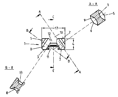
The invention relates to a roller cage with a prismatic
body for guiding at least one work roller provided for
rolling a crankshaft at a journals area to form laterally
spaced annular recesses in a first concave recess on a
first face of the prismatic body on one section of the
circumference of the work roller, with an axis of rotation
of the work roller being inclined at an angle at which the
distance between a section guided within the roller cage
and a longitudinal middle of the prismatic body is less
than the distance to a remaining section, with a first
channel-shaped recess along the longitudinal middle of a
top area of the prismatic body as a passage for a backing
roller for the work roller and a second channel-shaped
recess along the longitudinal middle on a bottom side of
the prismatic body which is opposite the first
channel-shaped recess, for holding the roller cage at an extremity
of a long limb of an L-shaped cage retainer member,
wherein on a second face of the prismatic body which is
opposite the first concave recess, at least one second
concave recess being identical in position and size to the
first concave recess, is provided for guiding the work
roller.

Revendications

Note : Les revendications sont présentées dans la langue officielle dans laquelle elles ont été soumises.


-8-
CLAIMS
1. A roller cage with a prismatic body for guiding at
least one work roller provided for rolling a
crankshaft at a journals area to form laterally
spaced annular recesses in a first concave recess on
a first face of the prismatic body on one section of
the circumference of the work roller, with an axis
of rotation of the work roller being inclined at an
angle at which the distance between a section guided
within the roller cage and a longitudinal middle of
the prismatic body is less than the distance to a
remaining section, with a first channel-shaped
recess along the longitudinal middle of a top area
of the prismatic body as a passage for a backing
roller for the work roller and a second channel-
shaped recess along the longitudinal middle on a
bottom side of the prismatic body which is opposite
the first channel-shaped recess, for holding the
roller cage at an extremity of a long limb of an L-
shaped cage retainer member,
wherein on a second face of the prismatic body which
is opposite the first concave recess, at least one
second concave recess being identical in position
and size to the first concave recess, is provided
for guiding the work roller.
2. The roller cage of claim 1, wherein the first and
second concave recess on the first and second face
of the prismatic body are arranged laterally
reversed in respect to each other, in relation to
the longitudinal middle of said prismatic body.

-9-
3. The roller cage according to claim 1, wherein on one
or more of the first and second faces of the
prismatic body two concave recesses each are
provided.
4. The roller cage according to any one of claims 1 to
3, wherein the second channel-shaped recess
comprises a bevel to each of the first and second
faces of the prismatic body.
5. The roller cage according to any one of claims 1 to
4, wherein the roller cage is made of bronze.

Description

Note : Les descriptions sont présentées dans la langue officielle dans laquelle elles ont été soumises.


CA 02355489 2005-03-02
- 1 -
ROLLER CAGE
The invention relates to a roller cage that forms part of
a tool intended for deep rolling recesses in crankshaft
journals or connecting rod journals of crankshafts. Such
a tool is for example known from EP 0 839 607 A1. In this
document the roller cage is designated with the reference
number 15 (see Fig. 1); it is guided at the end of an L-
shaped tool holder designated 20.
Work rollers are for example known from the US patent no.
5,806,184 where the work rollers are designated with the
reference number 40. Within the roller cages designated
26 in said patent specification, two work roller 40 are
guided, said rollers 40 at the same time being inclined
at an angle 42. The inclination 42 is such that the
distance between the sections of the work rollers 40
guided within the roller cages 26, and the longitudinal
middle of the work rollers 40 is less than the distance
to those sections of the work rollers 40 which are
located outside the roller cages (compare US patent
no. 5,806,184, Figs. 2 and 2a).
The work rollers designated 40 which are shown in the
printed patent specification are almost drawn to natural
size. Accordingly, the design size of a roller cage is
small, with the basic area for example being only 10 to
30 mm in width and 10 to 15 mm in length. The prismatic
basic body is between 8 and 15 mm in height. These
dimensions apply to a tool suitable for machining the
crankshafts of passenger motor vehicles.
The work rollers comprise hardened steel while the roller
cages comprise bronze which offers particularly

CA 02355489 2005-03-02
- 2 -
favourable gliding qualities while being wear resistant.
But other materials such as e.g. titanium or ceramics,
could also be considered for a roller cage.
Nonetheless, roller cages are exposed to increased wear
so that their tool service life is relatively short. With
progressive wear of the roller cages, the work rollers
too, are wearing. Such stress finally results in roller
cages and work rollers having to be replaced at the same
time if wear of the roller cage has reached a particular
stage.
It is thus the object of the present invention to
increase the service life of a roller cage so that while
using the same work roller, the service life of the work
roller tool as a whole can be increased.
In one aspect the present invention provides for a roller
cage with a prismatic body for guiding at least one work
roller provided for rolling a crankshaft at a journals
area to form laterally spaced annular recesses in a first
concave recess on a first face of the prismatic body on
one section of the circumference of the work roller, with
an axis of rotation of the work roller being inclined at
an angle at which the distance between a section guided
within the roller cage and a longitudinal middle of the
prismatic body is less than the distance to a remaining
section, with a first channel-shaped recess along the
longitudinal middle of a top area of the prismatic body
as a passage for a backing roller for the work roller and
a second channel-shaped recess along the longitudinal
middle on a bottom side of the prismatic body which is
opposite the first channel-shaped recess, for holding the
roller cage at an extremity of a long limb of an L-shaped
cage retainer member, wherein on a second face of the

CA 02355489 2005-03-02
- 3 -
prismatic body which is opposite the first concave
recess, at least one second concave recess being
identical in position and size to the first concave
recess, is provided for guiding the work roller.
Description of the Preferred Embodiments
It has been found that this object can be met in that on
the second face which is opposite the first concave
recess, at least one second concave recess being
identical in position and size to the first concave
recess, is provided for guiding the work roller.
After the first concave recess for guiding the work
roller has reached a specified depth of wear, the roller
cage is turned around within the tool and from that point
onwards the work roller is guided in the second concave
recess provided on the rear face of the roller cage,
until there too the permissible wear has been reached.
The result is an optimized use of the roller cage. Due to
its small size, the required precision and the complex
machining operations involved, such a roller cage is a
highly complicated component of the tool, whose
production is correspondingly expensive. As a result of
the improved use of this component according to the
invention, the entire economy of the work roller tool can
be increased.
As has been shown in the state of the art mentioned in
the introduction, it is usual to guide two work rollers
at the same time within a single roller cage. This
arrangement applies in the case of crankshafts along
which a connecting rod journals follows after, each
crankshaft journals. However, in the case of crankshafts
where two connecting rod journals are directly adjacent

CA 02355489 2005-03-02
- 4 -
(so-called split-pin crankshafts) it is standard practice
to only use a single work roller within a roller cage.
The present invention is designed to be suitable for such
applications, too. Accordingly, the first and second
concave recess on the first and second face of the
prismatic body are arranged laterally reversed in respect
to each other, in relation to the longitudinal middle of
said prismatic body.
On the outer extremity of the L-shaped tool holder the
roller cage is guided in a tongue-shaped extension of the
tool holder. This tongue-shaped extension engages a
longitudinal channel of the prismatic body of the roller
cage so that the entire work roller tool has a plane
finish towards the bottom, with only the non-guided
sections of the work rollers protruding from it. The
interaction between the roller cage and the L-shaped tool
holder necessitates the longitudinal channel within the
roller cage to comprise a certain bevel. Since in the
present case the roller cage is to be used from the
direction of both faces, it is provided for the bevel to
be inclined towards both faces of the roller cage. With
these means, particularly simple and effective holding of
the roller cage is achieved.
Below, the invention is described in more detail by means
of an embodiment. The following are shown in enlarged
scale:
Fig. 1 A front view of a roller cage;
Fig. 2 A section through the limb of a roller cage
along section A-A;

CA 02355489 2005-03-02
- 5 -
Fig. 3 A longitudinal section along the line C-C in
Fig. 1; and
Fig. 4 A section through the second limb of the roller
cage along the line B-B.
The roller cage 1 is of prismatic basic shape comprising
a rectangular top 2, an opposite bottom 3, lateral
elevations 4 and two opposite faces 5 and 6. The
reference characters of the bottom 3 and the top 2 in
Fig. 1 refer to the installed position of the roller cage
1 in the tool. On each of the faces 5 and 6, two first
concave recesses 7 and 8 or two second concave recesses 9
and 13 have been provided. The concave recesses 7, 8, 9
and 13 are meant to guide work rollers (not shown) on a
section of their exterior circumference. Fig. 2 shows
that the concave recess 7 is of round shape, dictated by
the round shape of the work roller. As is clearly shown
in Fig. 2, a recess 9 on face 6 corresponds to recess 7
on face 5. The recesses 7 and 9 are identical iri shape.
Furthermore, Fig. l shows that the two recesses 7 and 8
are arranged at an angle 10 to the longitudinal middle of
the prismatic roller cage 1, said longitudinal middle
extending along the sectional line C-C. A further recess
13, which is of the same shape, corresponding to recess
8, is arranged on face 6 of the roller cage 1 (Fig. 4).
On the bottom 3 of the prismatic basic body of the roller
cage 1 a first widened channel-shaped recess 11 is
provided. This first channel-shaped recess 11 extends
along the longitudinal middle line C-C. In the assembled
tool for example the outer extremity of its long limb
(not shown) of an L-shaped tool holder (not shown)
engages said first channel-shaped recess 11. Opposite the

CA 02355489 2005-03-02
- 6 -
first channel-shaped recess 11 on the top 2 a second
channel-shaped recess 12 has been provided which also
extends along the longitudinal middle line C-C of the
prismatic roller cage 1. The channel-shaped recess 12 is
bevelled in a downward incline towards both faces 5 and
6, as is clearly shown in the section of Fig. 3. In the
assembled tool a guide roller for the work roller (not
shown) engages the groove-shaped recess 12. The bevels 14
and 15 of the channel 12 meet approximately in the middle
of the longitudinal extension of the prismatic roller
cage 1.
The embodiment described shows that for example the
longitudinal extension 16 of the prismatic roller cage 1
is less than its width 17. This design has. been selected
with a view to the installation position of the.prismatic
roller cage 1 within the work roller tool.

CA 02355489 2005-03-02
_ 7 _
List of references
1 Roller cage
2 top
3 bottom
4 Height
Face
6 Face
7 Concave recess
8 Concave recess
9 Concave recess
Angle
11 First channel-shaped recess
12 Second channel-shaped recess
13 Concave recess
14 Bevel
Bevel
16 Longitudinal extension
17 Width

Dessin représentatif
Une figure unique qui représente un dessin illustrant l'invention.
États administratifs

2024-08-01 : Dans le cadre de la transition vers les Brevets de nouvelle génération (BNG), la base de données sur les brevets canadiens (BDBC) contient désormais un Historique d'événement plus détaillé, qui reproduit le Journal des événements de notre nouvelle solution interne.

Veuillez noter que les événements débutant par « Inactive : » se réfèrent à des événements qui ne sont plus utilisés dans notre nouvelle solution interne.

Pour une meilleure compréhension de l'état de la demande ou brevet qui figure sur cette page, la rubrique Mise en garde , et les descriptions de Brevet , Historique d'événement , Taxes périodiques et Historique des paiements devraient être consultées.

Historique d'événement

Description Date
Le délai pour l'annulation est expiré 2007-08-21
Lettre envoyée 2006-08-21
Accordé par délivrance 2006-05-09
Inactive : Page couverture publiée 2006-05-08
Inactive : CIB de MCD 2006-03-12
Inactive : Taxe finale reçue 2006-02-21
Préoctroi 2006-02-21
Un avis d'acceptation est envoyé 2005-09-15
Lettre envoyée 2005-09-15
Un avis d'acceptation est envoyé 2005-09-15
Inactive : CIB attribuée 2005-08-29
Inactive : Approuvée aux fins d'acceptation (AFA) 2005-07-27
Modification reçue - modification volontaire 2005-03-02
Inactive : Dem. de l'examinateur par.30(2) Règles 2004-09-03
Modification reçue - modification volontaire 2004-01-07
Lettre envoyée 2002-10-02
Modification reçue - modification volontaire 2002-09-17
Inactive : Transfert individuel 2002-08-08
Demande publiée (accessible au public) 2002-02-28
Inactive : Page couverture publiée 2002-02-27
Lettre envoyée 2001-12-05
Requête d'examen reçue 2001-11-07
Exigences pour une requête d'examen - jugée conforme 2001-11-07
Toutes les exigences pour l'examen - jugée conforme 2001-11-07
Modification reçue - modification volontaire 2001-11-06
Inactive : CIB en 1re position 2001-10-25
Inactive : Lettre de courtoisie - Preuve 2001-09-11
Inactive : Certificat de dépôt - Sans RE (Anglais) 2001-09-06
Exigences de dépôt - jugé conforme 2001-09-06
Demande reçue - nationale ordinaire 2001-09-06

Historique d'abandonnement

Il n'y a pas d'historique d'abandonnement

Taxes périodiques

Le dernier paiement a été reçu le 2005-07-12

Avis : Si le paiement en totalité n'a pas été reçu au plus tard à la date indiquée, une taxe supplémentaire peut être imposée, soit une des taxes suivantes :

  • taxe de rétablissement ;
  • taxe pour paiement en souffrance ; ou
  • taxe additionnelle pour le renversement d'une péremption réputée.

Les taxes sur les brevets sont ajustées au 1er janvier de chaque année. Les montants ci-dessus sont les montants actuels s'ils sont reçus au plus tard le 31 décembre de l'année en cours.
Veuillez vous référer à la page web des taxes sur les brevets de l'OPIC pour voir tous les montants actuels des taxes.

Historique des taxes

Type de taxes Anniversaire Échéance Date payée
Taxe pour le dépôt - générale 2001-08-21
Enregistrement d'un document 2001-08-21
Requête d'examen - générale 2001-11-07
TM (demande, 2e anniv.) - générale 02 2003-08-21 2003-07-17
TM (demande, 3e anniv.) - générale 03 2004-08-23 2004-07-13
TM (demande, 4e anniv.) - générale 04 2005-08-22 2005-07-12
Taxe finale - générale 2006-02-21
Titulaires au dossier

Les titulaires actuels et antérieures au dossier sont affichés en ordre alphabétique.

Titulaires actuels au dossier
HEGENSCHEIDT-MFD GMBH & CO. KG
Titulaires antérieures au dossier
FRANK RISTERS
HANS ZIMMERMANN
HERBERT KALB
SIEGFRIED BAGUSCHE
Les propriétaires antérieurs qui ne figurent pas dans la liste des « Propriétaires au dossier » apparaîtront dans d'autres documents au dossier.
Documents

Pour visionner les fichiers sélectionnés, entrer le code reCAPTCHA :


Pour visualiser une image, cliquer sur un lien dans la colonne description du document. Pour télécharger l'image (les images), cliquer l'une ou plusieurs cases à cocher dans la première colonne et ensuite cliquer sur le bouton "Télécharger sélection en format PDF (archive Zip)" ou le bouton "Télécharger sélection (en un fichier PDF fusionné)".

Liste des documents de brevet publiés et non publiés sur la BDBC .

Si vous avez des difficultés à accéder au contenu, veuillez communiquer avec le Centre de services à la clientèle au 1-866-997-1936, ou envoyer un courriel au Centre de service à la clientèle de l'OPIC.


Description du
Document 
Date
(aaaa-mm-jj) 
Nombre de pages   Taille de l'image (Ko) 
Dessin représentatif 2002-02-24 1 7
Abrégé 2001-11-05 1 36
Dessins 2001-11-05 1 14
Description 2001-11-05 6 215
Revendications 2001-11-05 2 58
Abrégé 2001-08-20 1 37
Description 2001-08-20 6 212
Revendications 2001-08-20 2 58
Dessins 2001-08-20 1 15
Abrégé 2005-03-01 1 30
Description 2005-03-01 7 225
Revendications 2005-03-01 2 47
Dessin représentatif 2006-04-09 1 7
Certificat de dépôt (anglais) 2001-09-05 1 175
Accusé de réception de la requête d'examen 2001-12-04 1 179
Demande de preuve ou de transfert manquant 2002-08-21 1 108
Courtoisie - Certificat d'enregistrement (document(s) connexe(s)) 2002-10-01 1 112
Rappel de taxe de maintien due 2003-04-22 1 107
Avis du commissaire - Demande jugée acceptable 2005-09-14 1 161
Avis concernant la taxe de maintien 2006-10-15 1 173
Correspondance 2001-09-05 1 23
Correspondance 2006-02-20 1 37