Note : Les descriptions sont présentées dans la langue officielle dans laquelle elles ont été soumises.
CA 02355539 2001-08-22
-1-
SELF-ALIGNING SPOOL AND METHOD FOR STORING STRIP COMPONENTS
Field of the Invention
The present invention is directed toward a method and apparatus for storing
strip
material. More specifically, the present invention is directed towards a
method and
apparatus for positioning a continuous strip of material onto a spool.
Background of the Invention
The present discussion is directed specifically towards the manufacture of
strip
material for building tires; however, the background art and the disclosed
invention may
also be applicable to other types of manufacturing wherein it is necessary to
store strip
material.
When forming a strip component, it may be desired to store the component in a
manner that prevents the destruction or alteration of any prefor-med cross-
sectional
configuration. This is frequently accomplished by storing the component in a
spiral
spool storage device. The component is placed on a liner that is spirally
wound inside
the spool. Spacing between adjacent rows of spirally wound liner prevents the
adjacent
layers of wound material from contacting, thus preserving the preformed cross-
sectional
configuration of the strip component.
U. S. Patent 5,412,132, JP 61-111261, and EP 621,124 illustrate such storage
devices. U.S. Patent 5,412,132 discloses a spool with stepped flanges wherein
a liner of
increasing width rests on the stepped flanges to support the component within
the spool
storage device. JP 61-111261 discloses a spool formed with protrusions for the
edges of
a liner to rest upon. EP 621,124 discloses a spiral spool storage device
wherein the
edges of the liner rest in continuous spiral grooves formed on the inner face
of the spool
flanges.
Because the space provided for the edges of the liner are of a relatively
small
dimension, the liner must be precisely fed to the storage spool. JP 61-111261
discloses
first feeding the liner through a fixed metal plate. The plate has an arcuate
shape with
flanged sides causing the plate to have a width less than the width of the
liner. The liner
is fed through the plate, inside the flanges, reducing the effective width of
the liner.
After the liner passes through the plate, the liner is feed onto the spool
prior. The liner
CA 02355539 2001-08-22
-2-
returns to its original width after once it is placed onto the spool, known in
the art as the
liner "popping" into place.
EP 621,124 also teaches reducing the effective width of the liner prior to
feeding
it into position on the spiral spool. Three different methods of reducing the
liner width
are disclosed. Two methods employ the use of curved bars through which the
liner
passes. The curved bars are in a fixed angular relationship with the rod upon
which the
bars are attached. The third method disclosed employs two pairs of deflecting
bars. The
first pair initially deflects the edges of the liner and the second pair
slides relative to the
spiral spool to ensure proper positioning of the liner onto the spool.
While the above methods accomplish the goal of delivering the liner to the
spiral
spool, these methods require precise placement of the liner to prevent the
liner from
popping out of place, and to prevent folding and creasing. When such problems
do occur
with the liner, the continuous manufacturing of the component must be stopped
to
resolve the problem. The present invention is directed to a method of
delivering the liner
to the spiral spool in a manner and by an apparatus which overcomes these
limitations
and issues of the known delivery systems.
Summary of the Invention
A self aligning spool has an axis of rotation and is adapted for storing
elastomeric
components of a profiled cross-sectional shape. The spool has a
circumferentially
compliant liner for spirally wrapping about the axis. The liner has a pair of
lateral edges.
Separate from the liner is a pair of traction spacers. One traction spacer is
located
adjacent each lateral edge of the liner. Each traction spacer has a width and
a thickness.
The thickness of the traction spacer establishes the radial space between each
spiral layer
of the circumferentially compliant liner. Each traction spacer is a separate
component of
the spool and is provided in strips of material preferably radially
compressible and
circumferentially stretchable. Most preferably the traction spacers are
elastomeric.
In the preferred embodiment the spool has at least one end having a
perpendicular
surface relative to the axis of rotation. The perpendicular surface of the at
least one end
provides a means to restrain lateral movement of the wound spool, its liner
and
associated strip applied to the liner.
A method for storing continuous lengths of formed strips of elastomeric
components having a profile cross-sectional shape onto a storage spool is
described.
CA 02355539 2001-08-22
-3-
The steps include placing the formed strip component on a liner having a pair
of
lateral ends and a pair of longitudinal ends, placing a traction spacer
adjacent each lateral
end of the liner, the traction spacers being strips having height or thickness
slightly
greater than the formed strips. The method further includes fixing a
longitudinal end of
the liner adjacent an axis of rotation of the spool, rotating the axis thereby
winding the
liner, the traction spacer and the strip into a spiral wherein the liner and
the traction strip
are radially supported by the traction spacers.
In the preferred method the additional step of restraining the lateral ends of
the
spool from lateral movement is provided for. The method further comprises the
step of
equalizing the diametrical dimension of each lateral end of the liner as the
liner is being
rotated to form the spiral. The step of equalizing the diametrical dimension
of each
lateral end includes the step of stretching the traction spacer of the lateral
end having the
larger diameter, thereby reducing the spacer thickness creating a reduced rate
of diameter
increase at one lateral end relative to the opposite end. The step of
stretching the traction
spacer on one lateral end more than the opposite lateral end is an automatic
function
whereby the torque applied to the traction spacers is greater at the larger
diameter end
thereby causing the strip to stretch and reduce its cross-sectional height or
thickness
automatically adjusting the diameter such that as the strip and spiral liner
is wound the
diameters are equalized and the torque generated approximates equal at each
lateral end.
Furthermore, the step of rotating the axis thereby winding the liner, traction
spacer and
formed strip component into a spiral includes the step of forming a
substantially airtight
pocket in which the formed strip component is positioned.
Brief Description of the Drawings
Figure 1 illustrates an apparatus for winding a formed strip component in a
perspective view.
Figure 2 is a plan view of the spool of Figure 1.
Figure 3 illustrates the cross-sectional view of the spiral spool with the
formed
strip component, liner and traction spacers are wound thereon.
Figure 4 is the view of Figure 3 showing an exaggerated tolerance misalignment
of the spiral thereby causing an increase torque at one end of the spiral
spool.
Figure 5 is a cross-sectional view of a traction spacer 40.
CA 02355539 2001-08-22
-4-
Detailed Description of the Invention
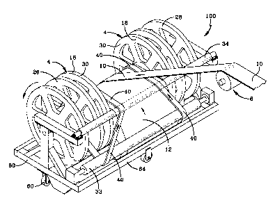
With reference to Figure 1 an apparatus 100 for incorporating the present
invention, for winding and storing a formed strip component 10 is illustrated.
The
apparatus 100 has a spool 4 onto which the strip component 10 is to be wound.
The strip
component 10 is preferably taken from a let-oil means after it has been
freshly formed
into its desired cross-sectional profile. The spool 4 upon which the strip 10
is to be
wound is mounted on an axle 14 coincident, but independent with the axis of
the spool 4
and upon which the spool 4 rotates. As the spool 4 rotates, a
circumferentially compliant
liner 12 is fed from one side of the spool 4 while the strip component 10 is
unlaid upon
the liner 12 of the spool 4. As this is occurring a pair of traction spacers
40 are applied
adjacent each lateral edge 22,24 of the liner 12 as illustrated. These
traction spacers 40
have a width (W) and a thickness (T) and as they are fed into the spool 4,
they provide a
spacing 30 in which the formed elastomeric strip component 10 can occupy
between
spiral layers of the liner 12.
In the preferred embodiment of the invention the spool 4 includes a pair of
spool
end flanges 16,18. These spool end flanges 16,18 are attached to the axis of
the spool 4
and provide a perpendicular surface relative to the axis of rotation of the
spool 4. These
flanges 16,18 restrain lateral movement of the spiral as it is being wound,
preferably
these flanges 16,18 have a smooth surface in which the liner 12 and associated
traction
spacers 40 a.nd the formed strip component 10 can easily slip therebetween.
The liner 12 preferably has a sufficient lateral width to extend between the
spool
flanges 16,18 to permit the liner lateral edges 22,24 to rest in close
proximity to the
flanges 16,18. This insures that the liner 12 does not telescope as it is
being wound.
The liner 12 must be formed of strong enough material so that the weight of
the
strip component 10, when wound up into the spool 4, does not cause the liner
12 to
deflect and crush or contact the component 10 stored upon radially inner
windings of the
stored component 10 and liner 12. The liner 12 when bent around the spool has
a
curvature which yields additional load carrying support. Preferred materials
for the liner
12 include rigid polyethylene, terephthalate, polypropylene, a.nd other
similar materials.
As illustrated the strip component 10 can be unvulcanized elements of a tire,
such
as sidewalls, tread, apex, or any other strip material that could be
susceptible of crushing
in conventional storage mechanisms.
CA 02355539 2001-08-22
-5-
As further illustrated, as the liner 12 is fed into the spool 4 adjacent each
lateral
edge 22,24 of the liner 12 a traction spacer 40 is inserted. As the liner 12
winds about
the spools axis, these traction spacers 40 provide a pocket or space 30 for
which the
formed strip component 10 is to be positioned. Preferably each traction spacer
40 has a
cross-sectional area as shown in Figure S defined by a thickness (T) and a
width (W). As
illustrated, in Figure 3, the traction spacers 40 are provided as strips of
material that is
radially compressible and circumferentially stretchable. As illustrated in the
preferred
embodiment the traction spacers 40 are elastomeric. It is believed important
that the
deformation of the traction spacers 40 be limited such that the formed strip
component
10 is not contacted by the liner 12 in the adjacent spiral layers as the
spiral is wound
increasing in diameter.
As further shown in Figure 3, the entire weight of the spool is supported at
the
lateral edges 22,24 by these traction spacers 40 being stacked in a vertical
fashion as the
spiral is wound. The spool 4 may include a round windup drum or cylinder 72 to
keep
1 S the diameter sufriciently large initially to enable the liner to
circumferentially bend
without distortion or crimping. At the drum a VelcroTM or other type adhesion
74 of the
liner 12 to the drum 72 can be used as illustrated. In the preferred spool 4
the user bends
the liner 12 into a slot in the drum 72 to secure the liner 12.
With reference to Figure 4 a view similar to Figure 3 is shown wherein an
exaggerated tolerance misalignment of the spiral is created thereby causing an
increased
torque at the end of the spiral having a larger diameter. When this condition
exists the
traction spacers 40 on the larger side of the spool are stretched thereby
causing a
reduction in thickness (T) of the traction spacer 40. As the traction spacer
40 thickness
(T) is reduced and the spiral continues to wind, the variation in diameter
from one side to
the other automatically is compensated for until the diameters are
approximately in equal
dimension. This self compensating diameter adjustment capability is believed
possible
because the traction spacers 40 are separate from the liner and are not
physically attached
to the liner which would restrain the ability to stretch.
Traditionally, in tire manufacturing the ability to wind components onto a
spool
is limited to an overall diameter of 42 inches. By use of the present
invention it is
possible to have spiral spools at approximately 72 inches in diameter, or
almost 2 meters.
For example, 60 meters of strip material 10 can be wound on a conventional
spool
whereas with the spool 4 of the present invention approximately 150 meters of
material
CA 02355539 2001-08-22
-6-
can be wound. This translates into 40 tires for the conventional type spool
and a 100
tires capacity on the spool 4 made according to the present invention.
A second advantage of having all the supported load transferred through the
traction strips 40 is that liner 12 damage can be reduced and the thickness of
the liner 12
can be reduced because the strength and load transfer occurs almost entirely
at the
traction spacer area. The ends 22,24 are fully supported while the central
portion of the
liner 12 only has to support each layer of material 10. This means the liners
12 can be
produced substantially thinner than in the past. Another advantage of the
present
invention is that the thickness of the helix can be changed or varied by
changing the
traction strip 40 thickness (T). This is beneficial when thinner materials
such as a
sidewall is produced when compared to a tread. By reducing the thickness of
the traction
spacers, even more material can be stored on the spool 4.
When the spools 4 are emptied, the liner 12 can be wound tightly upon its own
axis and the traction space 40 also can be wound tightly on their axis. This
greatly
reduces the storage of these spools 4
By making the traction spacers 40 of elastomeric material and positioning at
the
lateral edges 22,24 of the spiral means that a sealed pocket 30 with the air
mixture
contained is possible. This helps insure that the product is fresh when
delivered. To
further facilitate this as the spool 4 is wound, it is believed preferable to
tape or seal any
exposed longitudinal end. In the manufacture of tire components 10 this
feature is quite
beneficial because it allows the product that was recently extruded and
profiled to cool at
a slower rate which enables the strip component 10 to exhibit less thermal
shrink
variations. With reference to Figure 3 again the traction spacers 40 as
illustrated in the
preferred embodiment had a cross-sectional width of 50 millimeters and a cross-
sectional
height of 13.5 millimeters. Spaced centrally within each traction spacer 40
was a
plurality of holes 42 extruded into the strip. These holes were approximately
3/16' of an
inch (4.8 mm) and extended longitudinally throughout each traction spacer 40.
These
holes 42 add to the deformation capability of the traction strip 40 and help
reduce the
weight of this component.
In the prior art spools it was noticed that as the spool increased in diameter
the
profile of the component was smashed. At the top of the stored strip a torque
was
transmitted to the preformed component being carried on the liner such that
wrinkles
occurred in the lateral edges. These wrinkles created non-uniformity's in the
tire and
CA 02355539 2001-08-22
particular caused thickness variations. With regard to the present invention
all of these
negative aspects have been eliminated.
While it is appreciated that pocket liners have been used in the prior art,
the
present invention provides a novel way of creating a self adjusting spiral
wound spool
wherein the vertical height is established by separate components or spacers
referred
herein as the traction spacers 40 that are stretchable thereby causing a
reduction in
thickness to enable diametrical differences that would often occur in multiple
windings
of spirals to be automatically compensated for and eliminated. It was
confirmed in test
that the self aligning feature, when traction spacers 40 having an elastomer
shore
hardness of A of about 80, would initiate when 1.0 millimeter or less in
diameter
variation occurred. What this means is that the self aligning feature
initiates very
quickly at the onset of a misalignment in diameters, thereby insuring that the
equality of
the spiral is maintained throughout the various layers of the spiral. This is
important
because if the misalignment was substantially greater than this an angular
variation in the
spool could occur, and, therefore, this spool within various layers could have
a quite
severe angular orientation. Surprisingly this does not occur with the use of
the present
invention.
With reference to Figure 1 a, the preferred embodiment of the invention is
illustrated. The apparatus 100 has the spool 4 mounted onto a frame 80. The
frame 80
has wheels 60 enabling the entire apparatus 100 to be moved about freely. The
spool 4
has a diameter of about 72 inches and the apparatus 100 when fully loaded with
a wound
formed strip component 10 weighs about 7500 lbs. Naturally, motorized tow
motors are
used to move these large fully loaded spools 4.
As illustrated in the preferred apparatus 100, the traction spacers 40 are
mounted
in self contained spools 26,28 at each end of the spool adjacent the flanges
16, 18, and
are positioned onto the liner 12, and feed over a pair of rollers 33,34, prior
to being
wound onto the spool 4. As shown, as the spool 4 rotates, a formed strip of
component
10 is laid onto the liner 12 between the traction spacers. Alternatively, the
strip 10 can
be fed onto the liner 12 and wound under the drum 72 of the spool 4. Once the
spool 4 is
full, the entire apparatus 100 can be towed to a storage location or to the
tire building
station.
CA 02355539 2001-08-22
_$-
Ingeniously by reversing the direction of rotation, the liner 12 and the
traction
spacers 40 can be rewound to the unloaded position. When all the formed strip
component 10 is removed, the apparatus 100 can be taken back to a loading
station.
The apparatus 100 creates a totally self contained device for loading and
unloading a component in strip form. The spool 4 has self aligning traction
spacers 4
that compensate for and actually prevent misalignment of the helically wound
spool.
These features, when employed as taught herein, are the most efficient way to
store strip materials without damaging the profile of the formed strip
component 10.