Note : Les descriptions sont présentées dans la langue officielle dans laquelle elles ont été soumises.
CA 02356767 2009-05-04
METERING VALVE TO DELIVER LIQUID
Backaround of the Invention
iel of tbe IMent'ton
This invention relates to a metering valve for delivering liquid vaporizable
germicide to a sterilizer.
DescriRtion of the Related Art
Sterilization is used in a broad range of industrial and medical applications.
Sterilization is the complete destruction or the i,rreversible inactivation of
all the
microorganisms in the system. Sterilization can be performod, for exaznple,
with
heat or chemical treatment. Heat sterilization is nomially drnie using steam-
Some
equipment cannot withstand the heat or the moisture of stem treatrnent. As a
result,
chemical sterilization is now eommonly used.
Chernical sterilization can be done using alcohols, aldehydes such as
formaidehyde, phenols, ozone, ethylene oxide, chlorine dioxide, or hydrogen
peroxide. Hydrogen peroxide is commonly used for chemical sterilization.
U.S. Patent No. 4,653,876, discloses an exemplary sterilization process in
which a vaporizable germicide such as hydrogen peroxide is introduced into an
evacuated sterilization chamber. The vaporizable germicide vaporizes and is
allowed to disperse throughout the chamber and onto the items to be
sterilized. After
a period of time, electrical energy is applied to an electrode to form a
plasma to
complete the sterilization cycle.
Thc STERRAD Sterilization System is an exemplary hydrogen peroxide
sterilization system, commercially available from Advanced Sterilization
Products,
Irvine, California. Advanced Sterilization Products is a Division of Ethicon
Endo-
Surgery, Inc. The system employs an automated delivery system in which a
measured amount of the liquid germicide, typically aqueous hydrogen peroxide,
is
delivered to the sterilization chamber. Measured portions of the liquid
gertnicide are
provided in rupturable cells within a liquid cassette housing. The cassette
and the
delivrry system are fully dcscribed in the Williams et al. patents, U.S.
Patent
Nos. 4,817,800, issued April 4, 1989; 4,913,196, issued April 3, 1990;
4,918,262,
-1-
CA 02356767 2009-05-04
issued July 3, 1990; and 4,941,518, issued July 17, 1990.
Although the cassctte and the delivery system work weU, the delivery system
is complex and expensive. There is a nced for a delivery system which is
simpler
and less expensive than the cassette delivery system. Further, the volumes of
vaporizable germicide which can be delivered to the sterilization ehamber witb
the
cassette delivery system are limited to incremental volumes of singlc cells on
the
cassette. For example, 1%: cells of hydrogen peroxide cannot easily be
delivered
with the cassette delivery system. Because the arnount of hydrogen peroxide
required for sterilization depends on the size of the sterilization chamber,
the
quantity of equipment in the chamber to be sterilized, the materials from
which the
equipment to be sterilized is made, and many other factors, there are times
when it
would be useful to be able to add small additioral inerements of hydrogcn
peroxide
into the sterilization chamber rather than being limited to adding an entire
cell of
vaporizable germicide from a cassette.
Therc is a need for a simple, inexpensive system for metering vaporizable
germicide into a sterilization chamber in which the amount of vaporizable
germicide
can be varicd in small incremental increments. There is a need for a simple
vaporizable germicide delivery system which can deliver a wide range of
volumes of
vaporizable gerrnicide to match the needs of various sizes of sterilization
chambers.
Sur m_ary qf the Invention
One aspect of the invention involves a metering valve for delivering liquid to
system. The metering valve includes a body having at least a first and a
second
orifice; and a rotatable valve plug located in the body, where the rotatable
valve plug
prevents direct fluid communication between the first otifice and the second
orifice.
The valve plug includes at least one well, where the well comes into* fluid
communication separately with the ftrst orifice and the second orifice as the
valve
plug is rotated.
Advantageously, 'the orifices are located approximately 180 degrees apart in
the valve body. The valve plug can be rotated manually or with a motor. In an
embodiment, the valve plug includes at lcast two wells. The two wells may have
different sizes or shapes. Preferably, the first orifice is never brought into
direct
fluid communication with the second orifice as said rotatable valve plug is
rotated.
-2-
CA 02356767 2001-09-06
Another aspect of the invention involves a system for sterilizing equipment,
where the system includes a metering valve. The metering valve includes a body
with at least two orifices and a rotatable valve plug located in the body. The
valve
plug prevents direct fluid communication between the two orifices. The valve
plug
includes at least one well. The well comes into fluid communication separately
with
the two or more orifices as the valve plug is rotated. The system also
includes a
reservoir connected to a first orifice on the metering valve. The reservoir
contains
vaporizable germicide. The system also includes a sterilization chamber, where
the
sterilization chamber receives vaporizable germicide from a second orifice on
the
metering valve.
Preferably, the system also includes a vaporizer connected to the second
orifice on the metering valve. The vaporizer is in fluid communication with
the
sterilization chamber. Advantageously, the system also includes a vacuum pump
connected to the sterilization charnber. The system may include a source of
plasma.
An accumulator may be located between the second orifice on the metering valve
and the sterilization chamber. An on/off valve may optionally be located
between
the metering valve and the sterilization chamber and/or between the metering
valve
and the reservoir. Advantageously, the vaporizable germicide is hydrogen
peroxide.
Another aspect of the invention involves a method for sterilizing an article
in
a chamber. The method includes providing a source of vaporizable germicide, a
chamber, and a metering valve for delivering germicide to the chamber. The
metering valve includes a body having at least two orifices and a rotatable
valve
plug located in the body. The valve plug prevents direct fluid conununication
between the two orifices_ There is at least one well in the valve plug. The
well
comes into fluid communication separately with the orifices as the valve plug
is
rotated. The metering valve is in fluid communication with the chamber and the
source of vaporizable germicide. Rotating the valve plug transfers vaporizable
germicide from the source of germicide into the well and from the well into
the
chamber.
Advantageously, the method also includes reducing the pressure in thc
chamber. Preferably, reducing the pressure vaporizes the vaporizable
germicide,
sterilizing the article in the chamber. In a preferred embodiment, the
vaporizable
germicide is accumulated in an accumulator located between the metering valve
and
the chamber. The article may be contacted with plasma. Preferably, the
vaporizable
-3-
CA 02356767 2001-09-06
germicide is hydrogen peroxide. The method may also include opening or closing
a
valve between the metenng valve and the source of vaporizable gerrnnicide or
between the metering valve and the chamber.
Bbef Description of the Drawings
Figure 1 is a schematic drawing showing a sterilization system and a cross
section of a metering valve according to an embodiment of the invention;
Figure 2 is a schematic drawing of the sterilization system and metering
valve of Figure 1, where there are no optional on/off valves between the
metering
valve and the reservoir or the vaporizer;
Figure 3A shows a schematic cross sectional side view of a metering valve
according to an embodiment of the invention, where there is one well in the
valve
plug;
Figure 3B shows a schematic cross sectional view of the metering valve of
Figure 3A along the 3B-3B axis of Figure 3A;
Figure 4A shows a schematic cross sectional side view of a metering valve
according to an embodiment of the invention, where there are two wells in the
valve
plug;
Figure 4B shows a schematic cross section of the metering valve of Figure
4A along the 4B-4B axis of Figure 4A;
Figure 5 shows a schematic drawing of the sterilization system and metering
valve of Figure 1 after vaporizable germicide has been admitted into the
orifice on
the top of the metering valve of Figure 1;
Figure 6 shows a schematic drawing of the sterilization system and metering
valve of Figure 5 after the handle of the metering valve has been turned,
transferring
the vaporizable germicide in the well of the metering valve to the top of the
on/off
valve above the vaporizer;
Figure 7 shows a schematic drawing of the sterilization system and metering
valve of Figure 6 after the on/off valve above the vaporizer has been opened,
allowing liquid vaporizable germicide to be transferred from the top of the
on/off
valve into the vaporizer; and
Figure 8 is a schematic drawing showing a sterilization system, a cross
section of the metering valve of Figure 3A, and an accumulator above the
vaporizer.
-4-
_._
.____.
CA 02356767 2009-05-04
Aetailed ese 'ption of the Pre~rr d Embodiment -
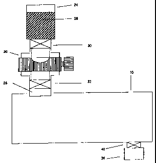
Figure 1 shows a schematic diagram of a sterilization chamber 10 with a
metering valve 20 according to an embodiment of the invention. The
sterilization
chamber 10 and its components and methods of use are described in detail in
U.S.
Patent No.4,756,882, issued July 12, 1988; U.S. Patent No.5,656,238, issued
August 12, 1997; and U.S. Patent No. 6,060,019, issued May 9, 2000. The
metering
valve 20 is mounted below a reservoir 24 which contains vaporizable germicide
26
and above a vaporizer 28 which is located above and which is fluidly attached
to the
sterilization chamber 10. Optional on/off valves 30 and 32 are located between
the
reservoir 24 and the metering valve 20 an/or between the metering valve 20 and
the
vaporizer 28. A vacuum pump 36 and a shutoff valve 40 are fluidly connected
with
the sterilization chamber 10.
Although the metering valve 20 is described in the context of a metering
valve for delivering vaporizable germicide to a sterilization chamber 10, it
is to be
=understood that the application of the metering valve 20 to sterilization is
illustrative
.only. The metering valve 20 of the present invention has many uses, and the
exarnple of delivering vaporizable germicide to a sterilization chamber 10
with the
metering valve 20 is not meant to be limiting. The tertn germicide is meant to
include either germicide or disinfectant. Further, the metering valve 20 can
be used
to deliver liquids, solids, and slurries of solids in one or more liquids.
Figure 2 shows a schematic diagram of a sterilization chamber 10 and
metering valve 20 in which there are no optional on/off valves 30 and 32
located
between the reservoir 24 and the metering valve 20 and between the metering
valve
20 and the vaporizer 28.
Figures 3A and 3B show two views of a meteri.ng valve 20 according to an
embodiment of the invention. The metering valve 20 has a generally rectangular
shaped body 44 with open orifices 48 at a top and a bottom of the body 44. As
seen
in cross-sectional side view Figure 3A and cross sectional end view Figure 3B,
the
two orifices 48 form an open tube extending through the body 44 of the
metering
valve 20. An roughly cylindrical valve plug channe150 extends through the body
44
perpendicular to the first open tube formed by the two orifices 48. The valve
plug
channel 50 forms a second tube in the body 44 perpendicular to the first open
tube
-5-
CA 02356767 2001-09-06
formed by the two orifices 48. The valve plug channel 50 in Figures 3A and 3B
contains a valve plug 52.
Although the body 44 shown in Figures 3A and 3B has a roughly rectangular
shape, the body 44 may have other shapes such as a cylindrical shape or other
appropriate shapes.
The valve plug 52 has a generally cylindrical center section, the barrel 56,
with a rod-like valve stem 60 extending from an end of the barrel 56. A handle
64 is
connected to the valve stem 60. Alternatively, a motor (not shown) can be
connected to the valve stem 60 in place of, or in addition to, the handle 64.
The tube formed by the two orifices 48 is plugged by the barrel 56 of the
valve plug 52. The barrel 56 of the valve plug 52 prevents fluid communication
between the two orifices 48 on the body 44 of the metering valve 20. The ends
of
the barrel 56 and the valve sterns 60 form a seal with the body 44 of the
metering
valve 20. The valve plug 52 may be rotated in the body 44 of the metering
valve 20
by turning the handle 60 or motor (not shown). The valve plug 52 is held in
place in
the body 44 of the metering valve 20.
In other embodiments, the valve plug 52 can have other shapes. For
example, in an embodiment, the valve plug 52 has the shape of a tapered
cylinder
rather than a simple cylinder, as in the embodiment shown in Figures 3A and
3B.
What is important that the valve plug 52 block the fluid communication between
the
two orifices 48 and that the valve plug 52 provide a seal with the body 44 of
the
metering valve 20_
There is a well 68 having a roughly semicireular shaped cross section in the
barrel 56 of the valve plug 52 in the embodiment of the metering valve 20
shown in
Figures 3A and 3B. The well 68 extends through only part of the barrel 56. In
other
embodiments, the well 64 can have other cross-sectional shapes such as a
rectangular shape, a V-shape, or a trapezoid shape. As seen in Figure 3B, the
well
68 is located under one of the orifices 48 when the valve plug 52 is placed in
the
body 44 of the metering valve 20 and when the well 68 is oriented so that the
well
68 is oriented with an open side of the well 68 directed upward. In other
embodiments, the well 68 is not centered under the orifice 48 but is located
asymmetrically below the orifice 48. At least a portion of the well 68 is in
fluid
communication with the orifice 48 when the open side of the well 68 is
directed
toward the orifice 48. Unlike a conventional valve, the orifices 48 of the
metering
-6-
CA 02356767 2001-09-06
valve 20 of Figures 3A and 3B are never in fluid communication with each
other, no
matter how the valve plug 52 is rotated.
The size of the well 68 may depend on the size of the sterilization chamber
10. In an exemplary embodiment, the well 68 has a size which is appropriate
for
holding an amount of vaporizable germicide 26 which is appropriate for the
smallest
sterilization chamber 10 to which the metering valve 10 is to be applied. In
an
embodiment appropriate for the STERREI.D stezilizer, the well 68 has a volume
of
approximately 1 milliliter. In embodiments appropriate for other sterilization
chambers 10, the wel168 has a volume larger or smaller than 1 milliliter.
Figures 4A and 4B show an alternative embodiment of the metering valve 20
in which there are two wells 68 in the barrel 56 of the valve plug 52. The
wells 68
are positioned on the valve plug 52 so that at least a portion of each of the
wells 68
is in fluid communication with an orifice 48 when the orifice 48 is aligned
with the
well 68. In the embodiment of the metering valve 20 shown in Figures 4A and
4B,
the two wells 68 are located on opposite sides of the valve plug 52. In the
embodiment of Figures 4A and 4B, when the well 68 at the top of the valve plug
52
is in fluid communication with the orifice 48 at the top of the metering valve
20, the
well 68 at the bottom of the valve plug 52 is in fluid communication with the
orifice
48 at the bottom of the metering valve 20. The two wells 68 are never in fluid
commuziication with each other, no matter how the valve plug 52 is rotated.
The two wells 68 of the metering valve 20 of Figures 4A and 4B are
approximately 180 apart from each another. In other embodiments of the
metering
valve 20 with two wells 68, the wells 68 are at not 180 apart from each
other, and
only one of the wells 68 may be in fluid communication with an orifice 48 at
any
one time. In this embodiment, rotating the valve plug 52 causes the other well
68 to
be in fluid communication with the orifice 48. In other embodiments, there may
be
three or more wells 68 in the valve plug 52. In all of the embodiments of the
valve
plug 20, the wells 68 are not in direct fluid communication with each other,
and the
orifices 48 are not in direct fluid conununication with each other. In the
embodiments of the metering valve 20 with at least two wells 68, the wells 68
can
have different sizes or shapes.
The metering valve 20 can be made from a wide range of materials,
including metal, glass, or plastic. Suitable metals include steel or aluminum.
Stainless steel is an exemplary metal for forming the metering valve 20.
-7-
CA 02356767 2001-09-06
TEFLONTm is an exemplary material for forming the metering valve 20.
TEFLONTM is the tradcname for polytetrafluoroethylene.
The seal between the valve plug 52 and the body 44 of the metering valve 20
can be achieved in several ways, depending on the material from which the
metering
valve is fabricated. If the valve plug 52 and the body 44 of the metering
valve are
both made of TEFI,ONTM, the valve plug 52 and the body 44 can be fabricated so
that the contact between the TEFLONTm valve plug 52 and the TEFLONTM body 44
forms a seal.
In another embodiment, the valve plug 52 is made of TEFLONTm, and the
body 44 is made of metal. If the valve plug 52 and the body 44 are properly
fabricated, the contact between the TEFLON'N valve plug 52 and the metal body
44
forms a seal. In another embodiment, the valve plug 52 is made of TEFLONTM,
and
the body 44 is made of glass. In another embodiment, both the valve plug 52
and
the body 44 are made of metal. 0-rings or packing can be placed on the valve
plug
52 to form a seal between the valve plug 52 and the body 44.
If 0-rings or packing are used in the metering valve 20, the 0-rings or
packing are preferably formed of a material which is resistant to the
vaporizable
germicide 26 which is used. VITONTM is an exemplary material for forming the 0-
rings or packing. TEFLONTm or silicone may also be used to form the 0-rings or
packing.
Returning to Figure 1, vaporizable germicide 26 is placed in the reservoir 24
above the optional on/off valve 30. The vaporizable germicide 26 can be any
liquid
vaporizable gennicide including hydrogen peroxide, peracetic acid, chlorine
dioxide,
ozone, or formaldchyde. In an exemplary embodiment, the vaporizable germicide
26 comprises aqueous hydrogen peroxide. In a prefenred embodiment, the
vaporizable germicide 26 is approximately 59 wt% aqueous hydrogen peroxide.
The
shutoff valve 40 between the vacuum pump 36 and the sterilization chamber 10
is
opened, and the sterilization chamber 10 is evacuated to a pressure of less
than 50
torr, more preferably less than 10 torr, and most preferably less than 1 torr
with the
vacuum pump 36. After the sterilization chamber 10 is evacuated, shutoff valve
40
between the vacuum pump 36 and the sterilization chamber 10 may be closed to
isolate the sterilization chamber 10 from the vacuum pump 36. In an
alternative
embodiment which will be described in more detail later, the shutoff valve 40
between the vacuum pump 36 and the sterilization chamber 10 is left open.
-8-
CA 02356767 2001-09-06
In Figure 5, the on/off valve 30 between the reservoir 24 and-the metering
valve 20 has been opened, allowing vaporizable germicide 26 to enter the
orifice 48
and the well 68 on the metering valve 20.
In Figure 6, the handle 64 or motor on the metering valve 20 has been
rotated, rotating the valve plug 52. As the valve plug 52 rotates, the
vaporizable
germicide 26 in the well 68 in the valve plug 52 of the metering valve 20
falls out of
the well 68 onto the top of on/off valve 32.
In Figure 7, on/off valve 32 has been opened, allowing the vaporizable
germicide 26 which was on top of the on/off valve 32 in Figure 6 to enter the
vaporizer 28. The vaporizer 28 is fluidly connected to the interior of the
sterilization
chamber 10. The vaporizer is maintained at a temperature of 60 to 70 C. As
the
vaporizable germicide 26 enters the hot vaporizer 28, the vaporizable
germicide 26
vaporizes, and the germicide vapor enters the sterilization chamber 10. The
germicide vapor contacts the equipment to be sterilized (not shown) in the
sterilization chamber 10, sterilizing the equipment. Optionally, plasma is
introduced
into or is generated in the sterilization chamber 10 to enhance the
sterilization by the
germicide vapor or to remove the germicide residual.
Returning to Figure 6, the handle 64 or the motor on the metering valve 20
can optionally be rotated more than one time. Each time the handle 64 is
rotated, a
volume of vaporizable germicide 26 equal to the volume of the well 68 is
delivered
to the top of the on/off valve 32. When the desired amount of vaporizable
germicide
26 has been delivered to the top of the on/off valve 32, the on/off valve 32
is opened,
allowing the vaporizable germicide 26 to enter the vaporizer 28. By knowing
the
volume of the well 68 and the number of times the handle 64 or motor has been
rotated, the amount of vaporizable germicide 26 which has been delivered to
the
vaporizer 28 can be determined.
In the embodiment of the metering valve 20 shown in Figures 4A and 4B,
there are two wells 68 on the valve plug 52. Each rotation of the handle 64 on
the
metering valve 20 delivers a volume of vaporizable germicide 26 equal to the
volume of the two wells 68, rather than the volume of a single well 68. The
embodiment of the metering valve 20 shown in Figures 3A and 3B thus delivers
twice as much vaporizable germicide 26 for each rotation of the valve plug 52
as the
embodiment of the rnetenng valve 20 shown in Figures 3A and 3B. Vaporizable
germicide 26 can enter the well 68 at the top of the metering valve 20 from
the
-9-
CA 02356767 2001-09-06
orifice 48 at the top of the metering valve 20 at the same time that
vaporizable
germicide 26 exits the well 68 at the bottom of the metezing valve 20.
In an alternative embodiment of the apparatus such as shown in Figure 2,
there is no on/off valve 32 below the metering valve. In the alternative
embodiment,
the vaporizable germicide 26 enters the vaporizer 28 directly after leaving
the well
68. The handle 64 on the metering valve 20 can be rotated multiple times to
add
more vaporizable germicide 26. In the altemative embodiment, the vaporizable
germicide 26 enters the vaporizer 28 incrementally each time the handle 64 is
rotated
rather than at one time when the on/off valve 32 is opened_
Figure 8 shows another embodiment of the apparatus suitable for delivering
larger volumes of vaporizable germicide 26 than the embodiment of the
apparatus
shown in Figure I_ In the ernbodiment of the apparatus shown in Figure 8,
there is
no on/off valve 30 between the reservoir 24 and the metering valve 20. In
another
embodiment, there is an on/off valve 30 between the reservoir 24 and the
metering
] 5 valve 20. An accumulator 76 is located between the metering valve 20 and
the
on/off valve 32 located above the vaporizer 28. The volume of the accumulator
76
is larger than the volume of the orifice 48 at the bottom of the metering
valve 20.
By including the accumulator 76 in the apparatus, a larger volume of
vaporizable
germicide 26 can be placed on top of the on/off valve 32 above the vaporizer
28 than
in the embodiment of the apparatus shown in Figure 1, where the volume of
vaporizable germicide 26 on top of the on/off valve 32 is limited to the
volume of
the orifice 48 at the bottom of the metering valve 20. After the desired
volume of
vaporizable germicide 26 has been delivered to the accumulator 76, the on/off
valve
32 is opened, delivering the vaporizable germicide 26 to the vaporizer 28.
Accumulating larger volumes of vaporizable germicide 26 in the accumulator
76 of Figure 8 has advantages over simply allowing the vaporizable germicide
26 to
enter the vaporizer 28 directly, when the vaporizable germicide 26 comprises
hydrogen peroxide and water. Water has a higher vapor pressure than hydrogen
peroxide. If the valve 40 between the sterilization chamber 10 and the vacuum
pump 36 is left open when the on/off valve 32 is opened, allowing the
vaporizable
germicide 26 to enter the vaporizer 28, water is preferentially removed from
the
sterilization chamber 10 into the vacuum pump 36, because the water has a
higher
vapor pressure than hydrogen peroxide, and the vapor in the sterilization
chamber 10
is ennched in water vapor compared to the vaporizable germicide 26 in the
-10-
CA 02356767 2001-09-06
accumulator 76. Removing water from the aqueous hydrogen peroxide in the
accumulator 76 by removing the water vapor in the sterilization chamber 10
concentrates the hydrogen peroxide.
After a certain period of time apparent to one of ordinary skill in the art,
the
valve 40 leading to the vacuum pump 36 is closed, and the concentrated
hydrogen
peroxide is allowed to vaporize from the vaporizer 28 into the sterilization
chamber
10. The concentrated hydrogen peroxide in the vaporizer 28 vaporizes to
produce a
vapor which has a highcr concentration of hydrogen peroxide than if water had
not
been removed from the aqueous hydrogen peroxide in the accumulator 76 by
preferential vaporization. The concentrated hydrogen peroxide vapor is more
effective at sterilization than hydrogen peroxide vapor produced from a less
concentrated solution of aqueous hydrogen peroxide.
Allowing the aqueous hydrogen peroxide vaporizable germicide to
accumulate in the accumulator 76 is therefore a preferred embodiment. The
aqueous
hydrogen peroxide in the accumulator 76 can be concentrated by removing water
vapor from the sterilization chamber 10 through the valve 40 and the vacuum
pump
36, improving the effectiveness of the sterilization.
The metering valve 20 of the present invention is an apparatus which
provides a way to readily deliver a wide range of volumes of vaporizable
germicide
26 to the sterilization chamber 10 without having to change the size of the
delivery
system, depending on the size of the sterilization chamber 10. The metering
valve
20 of the present invention is a simple device which is inexpensive to
manufacture
and easy to use. The volume of vaporizable germicide 26 which is delivered to
the
vaporizer 28 can be controlled by rotating the handle 64 or motor (not shown)
on the
metering valve 20. Each rotation of the handle 64 delivers a volume of
vaporizable
germicide 26 equal to the volume of the well 68 on the valve plug 52. The
incremental volumes of vaporizable germicide 26 to be delivered to the
sterilization
chamber 10 are not limited to the volume of a cell on a sterilization
cassette. If
multiple wells 68 are present on the valve plug 52, each rotation of the
handle 64
delivers a volume of vaporizable germicide 26 equal to the volume of each well
68
times the number of wells 68 on the valve plug 52.
In some embodiments, more than one metering valve 20 may be located in
parallel between the reservoir 24 and the vaporizer 28. The metering valves 20
can
have wells 68 of differing sizes or shapes. In this embodiment, the metering
valve
-11-
CA 02356767 2001-09-06.
20 can be selected for use which has a well 68 with a size which is optimal
for the
size of the sterilization chamber 10.
Various modifications and alterations of this invention will be apparent to
those skilled in the art without departing from the scope and spirit of this
invention.
It should be understood that the invention is not limited to the embodiments
disclosed therein, and that the claims should be interpreted as broadly as the
prior art
allows.
-12-