Note : Les descriptions sont présentées dans la langue officielle dans laquelle elles ont été soumises.
CA 02356859 2001-06-26
22-12-2000 GB 009904425
-1-
A PTFE TUBE
The present invention relates to a polytetralluoroethylene (PTFE) tube and
more particularly to a PTFE tube for a flexible hose. In particular the
invention
relates to a PTFE tube having a smooth bore for use in the production of a
lined
hose assembly further comprising hose braids, external hose protection and end
fittings.
It should be noted that there are two basic types of internal tube
configuration;
smooth bore tubes, as their name suggests, have a substantially convolution
free internal surface;
in contrast, internally convoluted tubes, as their name suggests, comprise
a number of distinct peaks and roots.
Of course smooth bore tubes are often not totally devoid of bumps and
indentations and may show rippling. This is however in sharp contrast to the
induced peaks and roots of an internally convoluted tube.
PTFE is a unique material and is favoured for applications in the transport
of foodstuffs and chemicals because of its chemical resistance and non stick
nature.
However PTFE is not naturally elastic.
Producing a flexible PTFE tube for certain applications, particularly high
pressure applications, where fluids, more particularly gases and vapours, are
pumped through the tube has proved difficult. Indeed, it had previously been
AMENDED SHEET
CA 02356859 2001-06-26
22-12-2000 GB 009904425 I,
-2-
thought that many convoluted PTFE tubes would not be suitable for such
applications because the "thinning" of the walls to produce "flex" was
expected to
result in increased permeation to fluids.
To reduce permeation one or more of the following techniques have hitherto
been employed:
1. Wall thicknesses have been increased;
2. Higher grade polymers have been used; or
3. Polymers have been processed to have increased crystalinity.
Increasing the wall thickness decreases the flexibility of the finished
product
as well as increasing its weight and cost.
Increasing crystalinity increases the flexural modulus of the material thus
decreasing the flexibility and this also incurs a reduction in flex Life.
Du Pont, for example, define crystalinity as being low (50 % ), moderately
high (72 % ) or very high (82 % ). At low crystalinity the product has a
flexural
modulus of 54,000 psi and a relative permeability to COZ gas of 6; at
moderately
high crystalinity the product has a flexural madulus of 150,000 psi and
relative
permeability to COZ gas of 0.8 and at a very high crystalinity the product has
a
flexural modules of 170,000 psi and a relative permeability to C02 gas of 0.2.
Most corrugated products are made by a process which convolutes or
concertinas the product and have walls which are substantially uniform in
thiclmess
throughout. Typical processes include those described in GB 1543586 and GB
2293222.
AMENDED SHEET
CA 02356859 2001-06-26
WO 00/39494 PCT/GB99/04425
-3-
EP 474449 B 1 on the other hand discloses a corrugated plastics tube which
has been subject to a compression force to displace material in the root
region. It is
characterised in that the compression force applied was sufficient to take the
plastics
of the tube, which was at a temperature below its melt temperature, beyond its
elastic
point. This can be achieved at any temperature below the melt temperature and
the
patent makes no specific teaching in this regard. Furthermore, the patent
relates to
plastics in general and is directed to producing flexibility. It is not
particular to PTFE
(although PTFE is specified) and it does not address the problem of producing
tubes
with improved permeability resistance to gases.
In contrast the present invention, which is particular to PTFE, teaches that a
novel product is obtained by a process comprising
1. subjecting the PTFE tube to a deformation force at a temperature at or
above the gel transition temperature of PTFE to produce constrained
convolutions
having a thinned wall W,; and
2. cooling the PTFE tube to below the gel transition temperature whilst
continuing to constrain the deformations having the thinned wall W, until the
convolutions having the thinned wall W, have become stable.
This product is characterised in that the convoluted PETE tube has an
improved resistance, of greater than 7.6 % , to permeation by comparison with
the
non-convoluted tube, the comparison being made between tubes of (i) equal
nominal bore ID; and (ii) equal weight of PTFE per unit length.
This improved resistance to permeation is indicative of the fact the product
CA 02356859 2001-06-26
WO 00/39494 PCT/GB99/04425
-4-
processed in this manner has a different form to one not so processed. This
can be
confirmed by way of the test procedure set out in the specific description.
Surprisingly, the applicants have discovered that by processing the PTFE,
which term includes modified PTFE, in a particular manner they are able to
reduce
permeation rates for a given thickness of PTFE. That the PTFE processed in
this
manner has a changed form can be characterised by amongst other things, its
improved resistance to permeation and increased tensile strength.
According to a first aspect of the present invention there is provided a
PTFE tube comprising external roots and peaks which tube is obtainable from a
non-convoluted tube having an original wall thickness Wo and an internal
diameter
ID by a process in which a region of the tube is thinned to provide external
convolutions with a root wall thickness W,, characterised in that the
convoluted
PTFE tube has an improved resistance to permeation of greater than 7.6 % by
comparison with the non-convoluted tube, the comparison being made between
tubes of (i) equal nominal bore ID; and (ii) equal weight of PTFE per unit
length.
Preferably the PTFE tube has a smooth internal bore.
In one embodiment the smoothbore has a rippled appearance.
According to a further aspect of the present invention there is provided a
method of producing a PTFE tube comprising external roots and peaks from a non-
convoluted tube having an original wall thickness Wo comprising:
1. subjecting the PTFE tube to a deformation force at a temperature at or
above the gel transition temperature of PTFE to produce constrained
convolutions
CA 02356859 2001-06-26
22-12-2000 GB 009904425
-5-
having a thinned wall W,; and
2. cooling the PTFE tube to below the gel transition temperature whilst
continuing to constrain the deformations having the thinned wall W, until the
convolutions having the thinned wall W, have become stable.
Preferably W, is less than 25 % of Wo.
More preferably W, is about 20 % of Wo. In a preferred embodiment the
PTFE tube is produced on a mandrel of substantially the same size as the
internal
diameter of a plane cylindrical PTFE paste extruded tube such that the
resulting
tube is a smoothbore, externally convoluted, tube. The resulting smoothbore
tube
has a rippled appearance.
That the deformation has become stable can be characterised by an increase
in tensile strength indicating that the deformation is a "yield" deformation.
The
deformation can be further characterised in that it is reversible. i.e. when
the
deformed material is reheated to at or above the gel transition temperature
without
a restraining force in place, it returns substantially to its original form.
It is also possible to determine whether or not the PTFE was deformed at
a temperature above or below the geI transition temperature. A tube deformed
below the gel transition temperature will revert partially or substantially to
its
original form at temperatures below the gel transition temperature whereas one
deformed at or above the gel transition temperature will only revert
substantially
to its original form at or above the gel transition temperature.
The increase in tensile strength can be seen by conducting a simple test. A
AMENDED SHEET
CA 02356859 2001-06-26
PCT/GB99/04425
WO 00/39494
-6-
longitudinal section is taken from a convoluted tube prepared in accordance
with
the invention and is gripped on either side of a root. It is then pulled apart
until
the section breaks at the root. By first determining the thickness and width
of the
root and noting the force applied to break the tube at its root the breaking
force per
cross sectional area can be calculated. Another section of the tube is then
heated
to above the gel transition temperature so it reverts to its starting
conformation and
the section is then subjected to the same test i.e. it is pulled along the
longitudinal
axis of the tube. Typical results obtained will be 41368 kPa (6000psi) for a
plain
tube and 75842 kPa (11000 Psi) for a convoluted tube manufactured in
accordance
with the invention.
The permeability properties of PTFE tubes deformed in this manner were
totally unexpected as a product which was more permeable was expected as a
consequence of a "thinning" of the walls.
For the avoidance of doubt the term gel transition temperature as used
herein refers to the temperature at which PTFE becomes more transparent and
amorphous. This is at a temperature of between 325°C and 340°C
and is generally
considered to be at a temperature of 327°C. This temperature is
sometimes
inappropriately, in a processing context, referred to as the melt temperature,
see
for example D.I. McCaine "Co-polymers with hexafluoropropylene" see page 630.
The true "melt" temperature is the temperature at which the polymer melts from
its gel state to form a liquid at which point it also begins to degrade and
evaporate
rapidly . This is at a temperature of above 550 ° , approaching "red
heat" , see for
CA 02356859 2001-06-26
WO 00/39494
_7_
PCT/GB99/04425
example R.J. Plunkett the inventor of PTFE.
Without wishing to be bound by theory it is believed that at temperatures
above 327°C a given applied deformation force is less likely to cause
"cut" than
the same deformation applied at temperatures below 327°C. Furthermore
because
the material is elastically deformed as opposed to being "cut" it benefits
from
improved characteristics, for example, improved resistance to permeability and
increased tensile strength. These characteristics show themselves in the
convoluted
tubes ability to revert substantially to its original form on re-heating to
above
327°C without a restraining force in place. The greater the "cutting"
during
processing the greater the depth of any "nicks" which appear in the so
reverted
product and the less it will resemble its original forth.
At processing temperatures below 327°C the deformations will
include, for
a critical force, deformations beyond the products elongation break point
which
will not repair. Only deformations beyond yield, and not those beyond the
products elongational break point will revert to their original shape on re-
heating
to above 327°C. "Cutting" can, of course, also occur at temperatures
above the
gel transition temperature if the deformation caused by the force is
sufficient. The
critical deformation will, however, be less at a temperature of below
327°C. Fox
example, a smooth bore convoluted tube processed at below the gel transition
temperature will, above a critical deformation, exhibit significant cut. Below
this
critical deformation a tube can only be thinned in the root region to between
one
third to one quarter of its original thickness. When processing at
temperatures
CA 02356859 2001-06-26
PCT/GB99/04425
WO 00/39494
_g_
above the gel transition temperature, the tube can be thinned to about one
fifth of
its original thickness without exhibiting cutting.
Thus, according to another aspect of the present invention there is provided
a PTFE tube comprising external roots and peaks, which tube is obtainable from
a non-convoluted tube having an original wall thickness Wo by a process in
which
a region of the tube is thinned to provide external convolutions with a root
wall
thickness W, characterised in that W, is less than 25 % of Wo.
Preferably W, is about 20 % of Wo.
The term "returns substantially to its original form" is intended to mean
that the reverted tube does not have significant convolutions, although it may
show
signs of limited damage caused by deformations beyond elongation at break
point
in the form of cuts or nicks. The product will, however, return to within 20%,
more preferably 10% and more preferably still 5% of its original wall
thickness
Wo
Because the force applied to the tube to form roots is 3-dimensional it
cannot readily be determined. However, the deformation can be measured as
indicated above. As a general rule greater deformations can be achieved
without
cutting at higher temperatures. Above 327°C deformation without cutting
is about
20 % better than below 327 ° C as indicated by the greater thinning
which can be
achieved when processing at temperatures above the gel transition temperature.
Of
course the deformations can not be fixed above 327°C therefore to fix
the
deformations a restraining force needs to be maintained whilst the temperature
is
CA 02356859 2001-06-26
WO 00/39494
-9-
dropped to below 327°C such that the deformations become stable.
PCT/GB99/04425
The invention will now be described, by way of example only, with
reference to Figs 1 to 6 in which:
Fig. 1 is a schematic diagram showing the reversable nature of the
production of a PTFE tube according to the invention;
Fig. 2 which is an enlarged sectional view of a segment of a PTFE tube
comprising external roots and peaks and a smooth internal bore;
Fig. 3 is a cut-away view of a hose assembly comprising a (liner) tube
according to the invention;
Fig. 4 is a graph showing maximum working pressure vs temperature for
different sized PTFE tubes according to the invention;
Fig. 5 is a graph of flow rate vs pressure drop for different sized tubes
according to the invention; and
Fig. 6 is a diagram of an apparatus used for conducting the permeability
test.
The invention is further illustrated with reference to a table, which shows
the specification of a number of different sized tube and hose assemblies.
Finally, examples with comparative data, showing the improved
permeability resistance of a tube processed in accordance with the invention
are
given.
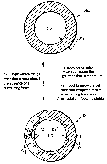
Referring to Fig. 1 a plane cylindrical PTFE paste extruded tube 10 with
a internal diameter LD. of 25.4 mm and a thickness Wo of 2.29 mm was heated
CA 02356859 2001-06-26
PCT/GB99/04425
WO 00/39494
-10
to 380°C on a suitably sized mandrel. A tool with an internal diameter
which was
greater than the outside diameter of the mandrel but less than the combined
diameter of the outside diameter of the mandrel and twice the wall thickness
Wo of
the plastic tube was bought into contact with the tube so that its leading end
applied
a pressure sufficient to displace material to form a smooth bored convoluted
tube
12 comprising roots 14, (with a root wall thickness W,) and peaks 16 (with a
peak
wall thickness W) whilst maintaining the tube at a temperature above the gel
transition temperature. The following end of the tool was maintained at a
temperature below the gel transition temperature such that the following end
of the
tool cooled the convoluted tube to below the gel transition temperature whilst
applying a restraining force such that the convolutions became stable. The
helical
tool was rotated relative to the mandrel at a speed of 18 revs per minute such
that
the leading end applied a 3-dimensional deformation force at above the gel
transition temperature and the following end applied a restraining force until
the
temperature had dropped below the gel transition temperature and the
convolutions
had become stable. In this regard, each section of the convoluted tube was
subjected to the restraining forces within the tool for approximately 1
minute.
Different shapes can of course be produced using the method. In one
embodiment a single start spiral corrugation may be formed. Alternatively
multiple
start spiral corrugations, annular corrugations, axial corrugations or a
combination
thereof can be produced.
The root wall should be thinned from 60 % to 5 % , preferably 50 % to 5 % ,
CA 02356859 2001-06-26
WO 00/39494 PCT/GB99/04425
-11-
of its original value Wo. For a fully corrugated shape the root wall should
preferably be thinned to 40% to 20% or its original value and for a smooth
bore
shape to 30 % to 20 % .
Preferably a radiussed rather than square edge to the thinned region is
formed.
As far as the width of the thinned area is concerned, working from original
wall thickness Wo, the width should be 10% - 200% of the peak wall thickness W
for smooth bore type constructions and typically 30 - 600%a of peak wall
thickness
for fully corrugated constructions. As the width tends to a greater percentage
so
the flexibility of the product increases.
The PTFE tube 12 has a root wall thickness W~ which is less than the peak
wall thickness W, when the root wall thickness W, has been reduced during
construction from a standard wall thickness Wo by compressing the tube to
displace
material.
Furthermore compression and displacement can cause the peak wall
thickness W to be greater than the original wall thickness Wo.
As illustrated in Fig. 1 the resulting tube can be returned to its starting
form
by reheating the tube 12 to above its gel transition temperature without a
restraining force in place.
Two sample tubes were subjected to a permeability test using an apparatus
CA 02356859 2001-06-26
WO 00/39494 PCT/GB99/04425
-12-
as illustrated in Fig. 6. The apparatus comprises a helium supply 50, a
pressure
regulator 52, a connecting tube 54 and a bleed valve 58. The test sample 56 is
connected between the connecting tube 54 and the bleed valve 58. The test
sample
is immersed horizontally in a water bath 60 and a collecting cowl 62 and
calibrating column 64 positioned thereover. The samples 56, which are known
lengths of PTFE tubing, are overbraided with end fittings swaged at both ends.
Prior to testing, the apparatus is first purged ensuring only helium remains
in the sample (it is held vertically with the bleed valve the lower end). The
sample
is then immersed in the water bath, supported horizontally, and the helium
pressure
is increased to the test pressure. The apparatus is left for a minium of 30
minutes
to allow steady state permeation to be achieved. The collecting cowl is placed
over
the sample, with water filling both it and the calibrated collecting column.
Collection of all permeating gas is timed and the amount recorded. The
procedure
is repeated several times to ensure steady state permeation has been achieved
and
the results are reproducible.
TP~t Conditions
Commercial grade Helium at 29.6 At (30 Bar) at room temperature.
Leakage is determined after steady state permeation has been reached on
the samples as follows:
Sample 1. Plain cylindrical tube with an internal diameter of 25.4mm and a
wall
thickness of 2.29mm over braided with steel, end fittings swaged at each end.
Sample 2. Smooth bore convoluted tube with an internal diameter of 25.4 mm
CA 02356859 2001-06-26
22-12-2000 GB 009904425
-13-
resulting from the processing of sample 1 in accordance with the methodology
described with reference to Fig. 1 over braided with steel, end fittings
swaged at
each end.
S~j~1 leakage rate 220 cc per hour per metre.
Sam~,e z_ leakage rate 150 cc per hour per metre.
Since the weight of the tube per unit length in sample 2 was approximately
20% less than the weight of the material per unit length of sample 1, the
figures
were adjusted to give a figure for a tube of a given weight.
Thus the specific improvement in permeation resistance is
2~Q x ~ =1.83
150 4
in other words, the specific permeation has been reduced in the ratio of
1:0.55.
Furthermore the flexibility is improved. In this regard sample 1 kinks at a
bend
radius of 381mm whereas sample 2 kinks at a bend radius of 63.Smm.
In a further test a comparison was made between a smoothbore externally
convoluted tube made by the method of the invention and one made entirely at a
temperature below 327°C.
The results of the comparison are given below:
Sample 3 (Plain tube). Leakage Rate 241cc/h/m
Sa 4 (Externally convoluted tube processed below 327 °C ) Leakage
rate
224cc/h/m.
AMENDED SHEET
CA 02356859 2001-06-26
WO 00/39494 PCT/GB99/04425
-14-
~~ (Externally convoluted tube processed above 327°C and below
550°C
and cooled below 327 °C with a restraining force). Leakage Rate
148cc/hr/m.
Figures are permeation rates of helium at 29.6 At (30 Bar) at room
temperature.
Below 327 °C there is an apparent improvement of 7.6 % whereas at
above
327 ° C there is a very significant improvement of 62. 8 % .
In practice it has been found that best results are achieved when the
temperature is between 327°C - 450°C, more preferably
327°C - 420°C , since
deformation is achieved without straining the material beyond the elongation
break
limit in any position in the convoluted configuration. The elongation limit
increases with the processing temperature.
Whilst the invention has been specifically described with reference to a
smooth bored convoluted tube, it will be apparent to the skilled man that
convoluted
tubes of various configurations can benefit from the method of the invention.
A tube as outlined above, particularly a smoothbore with external
convolution, has many applications since it overcomes the disadvantages of
either
conventional smooth bore or internally and externally convoluted flexible hose
designs, dramatically improving on many of their individual technical
performance
parameters.
The tube can be used as a hose liner in a hose assembly. It comprises (see
Fig. 2) integral rib sections (peaks) 16 which support the tube against
kinking,
vacuum and pressure and highly compressed web sections (roots) 14 leaving a
CA 02356859 2001-06-26
WO 00/39494 PCT/GB99/04425
-15-
smoothbore inner surface 18 which is rippled and provides excellent
flexibility.
A hose comprising a smoothbore externally convoluted PTFE tube
according to the invention shows significant improvement in properties when
compared to a conventional convoluted hose (both internal and external
convoluted). These include:
Vastly improved hygienic cleanability due to its smoothbore and polished
surface finish;
Flow Rates which are more than 100 % higher.
Pressure Ratings which are more than 50~ higher.
Gas Permeation Resistance which is more than 150 % higher; and
Flex Life at Temperature and Pressure which is more than 50 times the life
(dependent upon test conditions).
One type of hose comprising a PTFE tube according to the invention, is
illustrated in Fig. 3. It comprises a PTFE liner tube 20, with external
convolutions 22 of peaks 24 and roots 26 and a smooth internal bore 28 with
slight
ripples 30. The inner surface has been hot polished. The liner tube has a
flared
end 32. The external surface of the liner is covered with a braid 34 over most
of
its length. Attached to the ends of the tube are end fittings 36. A spigot 38
lies
between the tube and braid and is secured by a ferrule 40.
The PTFE (line tube is either made from FDA approved PTFE (hose grade)
or is made antistatic by the inclusion of, for example, carbon black.
The former is, for use in all applications where fluids conveyed are not
highly
CA 02356859 2001-06-26
WO 00/39494 PCT/GB99/04425
- 16-
electrically resistant. The latter is suitable for use in applications where
electrically
resistive fluids, such as fuels, solvents or freons are being conveyed. The
antistatic
nature of the tube prevents a damaging electrostatic charge build-up inside
the
hose.
The unique properties of the smoothbore, externally convoluted tubes make
them suitable for use in circumstances where conventional PTFE lined hoses
would
not be suitable.
In particular, hoses with a 15 mm - 50 mm hose bore size can be used at
full vacuum up to 130°C. Above this the vacuum resistance should be
reduced
1 % for every degree over 130°C. Fig. 4 shows the relationship between
maximum
working pressure (in Bars) vs temperature in °C for a range of hose
sizes.
Flow rates are also greater than for conventional convoluted PTFE hose.
In a straight configuration, using water as a test medium, flow rates as
illustrated
in Fig. 5 can be achieved.
In practice, flow rates will vary with hose flexing, fluid viscosity, end
fitting design and other parameters, but in general hose flow rates 2-3 times
better
than conventional convoluted PTFE hose were achieved.
The specification of typical products are illustrated in Table 1 below.
CA 02356859 2001-06-26
WO 00/39494 _ ~ ~ _ PCT/GB99/04425
O O N tNn O ~' ~ ~ p p
_ tC g
0 0WO N W
0o i~ O
o
o W ~, ~ o
w ~, o :~ a
0
.~
t/~~dtn.-j mbcn..~ v~"oin~.~ ~nb~H wbm.j v~bt/~.-~ Gd
~dd~0 .~~~'O ~t~~'O .~G~~O ,~~~'O ~~1~'O
.. ,.., .~ . ~..~ .. ..
0~ 0~ ' N~ p ' ~ ~ w ~ 1ra w w ~ W N N ~ N ...
Ov N ~ N 0C lH N ~O 0e Ja ~ O U1 i~ N 0C Ov ~ '~"b
~7 IJ tJ Ge 00 00 v W 1 C trW O C Ge ~ O C? a
.,
A.
N ... ~. N ... r ~... r .r 00 oe ~-~ r J J ~... J ~n W J 0v w w Ov
O O ~ O O ~ ~ O O W U O p O O p V' O O tn O 00 0o O
A.
W r W w ~ N i~ lA i1 N .~f OW~A N U1 00 W 41 ~w1 w J
O N O O O O t,n W n O W O ~ O O O O 1n O O
.
r GT r r~~ n-. po r N r. ~ r. N N .-~ N w N .-~ N ? N .-~ N ;s
N O N N Ov O Cv O o0 0o i~. O O O O. -0~ N ~ O oo ? oe O
O O O O O O O O O O O O O O
A
.. ... .. ~-. r r o--. .... N N N N N N N N N N N N N N N N
O O O O J J J J O O O O O O O O O O O O O O O O
N r-. rr r.. r ~ .... ~ ~~ J pp 11. 1C la T la lA tJ p N ~ W N tJ rr ~ Ci
lA CWO tJ t,n O ~r Ow~ N cn W N J W OWn 00 O O ~O N ~O tw
01 O O NW !~ O ~
CA 02356859 2001-06-26
WO 00/39494 PCT/GB99/04425
_l8_
Maximum Operating Temyeratures: SS Braid -70 ° C to + 260 °
C, PB Braid -
30°C to +90°C. SS, RC and SS, FP -40°C to +120°C,
SS,SI -40° to +180°C.
Pressure Variation with Temperature: SS Braid as per Fig. 4; PB pressure as
above over whole temperature range; RC, FP and SI grades are per Fig. 4, BUT
only within the temperature range for the particular grade.
TO tube only
SS Stainless Steel
PB Polypropylene
RC Rubber covered
FP Fire proof
SI Silicon rubber covered.
CA 02356859 2001-06-26
WO 00/39494 PCT/GB99/04425
-19-
A PTFE tube may be used as a lightweight hose per se, in applications
where working pressures are low and where there is no need for the physical
protection offered by an external braid.
Stainless steel (SS) braided hose is used in applications involving high
temperatures and working pressures. High tensile grade 304 stainless steel
wire
is used, to give maximum pressure resistance and external protection to the
hose.
Polypropylene braided (PB) hose is often preferred in application involving
frequent handling and movement of the hose, and where temperatures are within
the range -30°C and +90°C. PB braid is lighter in weight, and
any broken strands
will not cut the operator's hands. In addition, PB braid is not prone to
chloride
stress corrosion.
Additional external protection may be provided over the braid.
For the most rugged applications where the hose may be subjected to rough
treatment and severe external abrasion a rubber covering is provided it may
also
be added for hygienic applications, where external smoothness and cleanability
of
the hose is of prime importance.
The preferred rubber is EPDM which has excellent chemical resistance, and
is temperature resistant up to 120°C.
Other external protection which may be used includes fireproof rubber;
silicon rubber (resistant up to 180°C and clear); scuffrings and
protection coils.
A wide range of fittings may be incorporated to form a hose. They include
swivel flux fittings (as illustrated in Fig. 3) or DIN 11851 fittings (male
and
CA 02356859 2001-06-26
WO 00/39494 PCT/GB99/04425
-20-
female); cam action fittings, frictioned fittings and SMS and RTT fittings.