Note : Les descriptions sont présentées dans la langue officielle dans laquelle elles ont été soumises.
CA 02357099 2001-09-05
00-PCS-210 1
A DRIVE CIRCUIT FOR THE TRIP ACTUATOR OF A
NETWORK PROTECTOR AND A NETWORK PROTECTOR
INC'.ORPORATING THE SAME
BAC.'KUROUND OF THE INVENTION
Field of the Invention
This invention relates to apparatus for protecting electric power
distribution networks, and snore particularly, to a network protector with a
drive
circuit for controlling a trip actuator powered by network voltage which can
vary over
a wide range.
Background Information
Electric power distribution networks which supply power to a specified
area such as, for example, a section of the city, an industrial complex or a
large
building, are fed at multiple points through feeders which each include a
network
protector. A network protector is a circuit breaker adapted to trip and open
the feeder
upon detection of reverse power flow, that is. power flowing through the
feeder out of
the network rather than into the network. Typically, overcurrent protection is
provided by other devices such as fuses in series with the network protector.
The network protector is energized by the voltage on the network at the
point of connection of the network protector. Standards require that the
network
protector be able to trip at network voltages as low as 7% of rated voltage.
Conventional network protecaors have been able to accommodate sufficiently
large
trip actuator coils having an impedance capable of limiting coil current at
the high end
of the voltage range while still being able to operate at the low end. A new
design of
network protector utilizes a circuit breaker which is very compact, and
accordingly,
has trip coils which are smaller. The problem is exacerbated by the
requirements of
some users that the network protector be able to operate at higher than rated
voltage,
by as much as 50%. This extended range of operation, when combined with the
smaller physical size of newer trip coils presents a formidable challenge to
providing
a trip actuator having sufficient impedance to limit coil current at the high
voltages
while still being able to oper<~te at the low limit of network voltage. It
must also be
CA 02357099 2001-09-05
00-PCS-210 2
taken into consideration that network protectors are called upon to trip quite
frequently and therefore muss: have significant cycle life.
There is a need, therefore, for an improved network protector and trip
actuator therefor which can operate over the full range of required trip
voltages
without burning out the coil.
SjJMMARY OF THE INVENTION
This object and others are satisfied by the invention which is directed
to a network protector having separable contacts and an operating mechanism
opening
the separable contacts when actuated. The operating mechanism is actuated by
energization of a trip actuator coil. A control relay generates a trip signal
in response
to detection of power flow out of the network. A coil drive circuit responsive
to the
trip signal and powered by the voltage in the protected network energizes the
coil.
This coil drive circuit incorporates a current limner limiting energizing
current to the
coil to a specified value regardless of the wide variation in voltage in the
protected
network.
The coil drive circuit includes an electronic switch connected in series
with the coil and a control circuit which turns the switch on when the coil
current is
less than the specified value .and turns the electronic switch off when the
coil current
exceeds the specified value. 'The control circuit includes a current detector
generating
a current detector signal proportional to the coil current, a reference signal
generator
generating a reference signal proportional to the specified coil current and a
comparator which compares the detector signal to the reference signal. The
electronic
switch is turned on when the current detector signal is less than the
reference signal
and is turned off when the current detector signal becomes greater than the
reference
signal.
The control circuit further includes a latch latching the comparator to
turn the electronic switch off once the current becomes greater than the
reference
signal.
The coil drive circuit can include a voltage generator which generates a
coil supply voltage proportional to the voltage in the network. This coil
supply
CA 02357099 2001-09-05
00-PCS-210 3
S voltage is applied across the coil and the electronic switch. The control
relay includes
trip contacts which connect this voltage generator to the network to energize
the coil
upon detection of the reverse power flow condition. The reference signal is
generated
from the output of the voltage generator as a constant value signal
proportional to the
selected coil current.
The invention also embraces a drive circuit for a trip actuator coil in a
network protector providing ;protection to an electric power distribution
network over
a wide range of network voltages. This drive circuit comprises a voltage
source
selectively powered by the network and generating a coil supply voltage
proportional
to the network voltage where powered. An electronic switch is connected in
series
with the trip actuator coil and the voltage source so that the coil supply
voltage is
applied across the trip actual:or coil with the electronic switch turned on.
The drive
circuit further includes a control circuit energized by the voltage source
which turns
the electronic switch on when energized by the voltage source and turns the
electronic
switch off when current through the trip actuator coil exceeds a specified
value. The
control circuit includes a current detector generating a current detector
signal
proportional to the coil current and a reference signal generator generating a
reference
signal proportional to the specified value of coil current. A comparator
compares the
current detector signal to the; reference signal and turns the electronic
switch on as
long as the current detector signal is smaller than the reference signal. When
the
current detector signal becomes greater than the reference signal, the
electronic switch
is turned off.
BRIEF DESCRIPTION OF THE DRAWINGS
A full understmding of the invention can be gained from the following
description of the preferred embodiments when read in conjunction with the
accompanying drawings in wlhich:
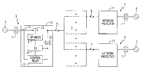
Figure 1 is a schematic diagram of an electric power distribution
network protected by network: protectors incorporating the invention.
Figure 2 is a schematic circuit diagram of a trip actuator coil and coil
drive circuit which form part ~of the network protector.
CA 02357099 2001-09-05
oo-rcs-Zio 4
DESCRIPTION OF THE PREFERRED EMBODIMENTS
Referring to Figure 1, an electric power distribution network 1 is fed
by a number of sources 3 through feeders 5. Each of the feeders 5 has a
transformer
7, a fuse 9, and a network pr°otector 11. The fuses 9 provide
overcurrent protection
while the network protectors 11 provide protection against reverse flow of
power
from the network 1 toward the sources 3. The electric power distribution
network 1 is
a three phase system and hence the components described to this point are also
three
phase, although shown in sinp~le line form for clarity.
The network protectors 11 include separable contacts 13 which are
automatically opened by an operating mechanism 15. The operating mechanism 15
is
actuated by a trip actuator assembly 17 in response to a trip signal from a
control relay
19. The control relay 19 monitors the current in the feeder 5 through current
transformer 21. A voltage proportional to the network voltage is provided to
the
control relay 19 and to the trip actuator assembly 17 through a potential
transformer
23.
As mentioned, newer circuit breakers used for the network protectors
11 are smaller and more compact. An example of such a circuit breaker is
provided in
US Patent 6,072,136. As also discussed, the physically smaller trip actuators
17 in
such circuit breakers have made it difficult to meet the requirements for the
wide
range of network voltages at which the network protector must operate. In view
of
the difficulty in providing a physically small trip coil with sufficient
impedance to
operate at the high end of network voltages at which the network protector
must
operate, the invention solves the problem by limiting the current which can
flow
through the trip coil. This limiting of coil current is effected by the coil
drive circuit
25 which forms part of the trap actuator assembly 17 shown in Figure 2 and
energizes
the trip coil 27. The impedance of the trip coil 27 is increased over the
prior art coils
by using an increased number of turns of smaller gauge wire for the coil.
However,
this is not sufficient to prevent burnout of the coil with operation at the
higher
voltages, hence the need for current limiting by the coil drive circuit.
The coil drive circuit 25 is energized by the network voltage through
the transformer 23 and trip contacts 29 of the control relay. When the
separable
CA 02357099 2001-09-05
00-PCS-210 5
contacts 13 open, auxiliary contacts 31 on the circuit breaker open to de-
energize the
coil drive circuit 25. A voltage generator 33 includes a full wave rectifier
bridge 35
protected by a varistor 37. The rectifier 35 produces a pulsed do coil supply
voltage
which is proportional to the network voltage. 'this coil supply voltage is
applied
across the trip coil 27 by an electronic switch such as the FET 39 connected
in series
with the coil. The coil supply voltage is also applied to a voltage regulator
41 which
includes a capacitor 43 charged to the peak value of the pulsed do current
through the
diode 45. A resistor 47 limits the charging current to the capacitor 43. A
zener diode
49 provides a regulated voltage of about 8 volts. Current to the zener is
limited by the
resistor 51. A capacitor 53 provides smoothing of the regulated voltage. This
regulated voltage is used by a control circuit 55 which controls operation of
the
electronic switch 39. The control circuit includes a pair of dual op amps 57
and 59
which are powered by the regulated voltage applied to pins 4 and 8. The
regulated
voltage is also applied to a reference signal generator 61 formed by the
resistors 63
and 65 connected as a voltagn~ divider across the zener diode 49. The
reference signal
is applied to the inverting input of the op amp 57 and the non-inverting input
of the op
amp 59. The control circuit 55 and electronic switch 39 together form a
current
limner which limits current through the coil 27 to a specified value
established by the
reference signal generator (~1 formed by the resistors 63 and 65.
The control <;ircuit 55 also includes a current detector 67 which
provides a measure of the coil current. This current detector includes a pair
of parallel
connected resistors 69 in series with the electronic switch 39 and trip coil
27. When
voltage is first applied to the circuit, the voltage developed across this
resistor
combination by coil current is applied through resistors 71 and 73 to the non-
inverting
input of op amp 57 which operates as a comparator to compare the detector
current
represented by the voltage across the resistor 69 to the reference signal
generated by
the reference signal generator 61. With the detector current signal smaller
than the
reference signal, the output of op amp 57 is low and the output of op am 59 is
high to
turn on the electronic switch 39. However, when the coil current increases and
the
detector current signal exceeds the reference signal, the output of op amp 57
goes
high and is latched in this state by feedback through the resistor 73. Thus,
the op amp
CA 02357099 2001-09-05
00-PCS-210 6
57 is latched which in turn latches the output of op amp 59 to the low state
once the
coil current has exceeded the specified value represented by the reference
signal. A
capacitor 75 assures that upon initial energization of the coil drive circuit
the output of
op amp 57 is low and the output of op amp 59 is high to turn the electronic
switch 39
on and the op amp 57 is turned off. A capacitor 76 connected between the
feedback
loop of the op amp 57 and ground assures that the circuit does not trip on
noise.
In the preferred embodiment of the coil drive circuit 25, shown in
Figure 2, a delay circuit 77 is provided between the output of the op amp 59
and the
gate electrode of the FET 39. The delay circuit 77 is formed by the series
resistor 81
and shunt capacitor 83, the values of which are selected so that gate drive
voltage for
the FET 39 is delayed (approximately 2 milliseconds) to assure that coil
current does
not flow before the reference signal generator 61 voltage is established. The
resistor
85 provides a dummy load for the op amp 59 output on initial power up while
the
zener diode 87 protects the input gate of the FET 39 from possible overvoltage
conditions generated with high voltage transients on the drain of the FET 39,
and the
resistor 89 limits current to the gate of FET 39. The diode 91 is used to
rapidly
discharge capacitor 83 and thus, turn off the FET 39 when the output of op amp
59
goes low.
The operation of the trip actuator assembly 17 of Figure 2 is as
follows. Under normal operation of the network protector, the separable
contacts 13
are closed so that the auxiliary contacts 31 are closed. However, the trip
contacts 29
are open so that the coil drive circuit 25 is de-energized. If the control
relay 19 (see
Figure 1 ) detects reverse current flow in the associated feeder 5, the trip
contacts 29
close to provide a voltage to the coil drive circuit 25 which is proportional
to the
voltage in the protected network. This ac voltage is full wave rectified by
the bridge
35 and rapidly charges the capacitor 43 of the voltage regulator 41 to the
peak value
of this voltage. The do supply voltage set by the zener diode 49 is rapidly
applied
through the capacitor 75 to the inverting input of the op amp 57 and the non-
inverting
input of the op amp 59 to assure that the latch is off and that the output of
the op amp
59 is high. As the supply voltage stabilizes, the reference signal generator
61 applies
the reference signal proportional to the selected maximum coil current to both
the op
CA 02357099 2001-09-05
00-PCS-210 7
amp 57 and the op amp 59. As of this point, the FET 39 is off, the output of
the
current detector 67 is zero, and therefore, the output of the comparator 59
goes high.
This gate drive signal is delayed by the delay circuit 77 before being applied
to the
gate 79 to turn on the FET 39. This applies the coil supply voltage generated
by the
bridge circuit 35 to the trip coil 27. The coil current which is initially
low, flows
through the resistors 69 of the current detector 67 to generate a current
detector signal
which is applied to the op amp 57. As long as the coil current remains below
the
specified current, the FET 39 remains turn on. In the exemplary coil drive
circuit 25,
the specified current is about: 1.2 amps. With the delay imposed by the delay
circuit
77, it may require a couple of half cycles for the coil current to build up to
1.2 amps at
the lower trip limit for the network voltage. With the voltage at the high end
of the
range, the 1.2 amps can be reached in less than 2 milliseconds.
When the coil current reaches the specified value, so that the current
detector signal exceeds the reference signal, the output of op amp 57 goes
high to
drive the output of op amp 59 low. The diode 91 allows the capacitor 83 to
rapidly
discharge so that the FET 39 is turned off. While this reduces the detector
current to
zero, the op amp 57 latches 'the output of the op amp 59 in the low state.
Thus, the
coil drive circuit 25 is latched in the off state. With the FET 39 turned off,
current in
the coil 27 circulates through the free-wheeling diode 93 to avoid voltage
spikes and
assure that the network protector is tripped. When the separable contacts of
the
network protector open, the auxiliary contacts 31 are opened to de-energize
the trip
actuator assembly 17 and reset the coil drive circuit 25.
While specific; embodiments of the invention have been described in
detail, it will be appreciated by those skilled in the art that various
modifications and
alternatives to those details could be developed in light of the overall
teachings of the
disclosure. Accordingly, the particular arrangements disclosed are meant to be
illustrative only and not limiting as to the scope of the invention which is
to be given
the full breadth of the claims appended and any and all equivalents thereof.