Note : Les descriptions sont présentées dans la langue officielle dans laquelle elles ont été soumises.
CA 02357144 2001-09-11
212/298
Shoe With Inflatable Bladder And Secure Deflation Valve
Field of the Inventions
The inventions described below relate to the field of
valves, and more specific:ally to valves suitable for use with
inflatable garments such as shoes and boots.
Background of the Inventions
A number of shoes and boots may be improved with the use
of air bladders placed within the shoe or boot. The air
bladders are preferably selectively inflatable and deflatable,
so that a wearer can adjust the fit of the shoe. The pump
device is popular with basketball shoes, ski boots, and
snowboard boots. Lakic, Miniature Universal Pump And Valve
For Inflatable Liners, U.S. Patent 5,846,063 (Dec. 8, 1998)
illustrates a number of embodiments of such inflatable
garments, and a number of emdodiments for various components
of the devices.
The inflatable shoe>s use a bladder pump for inflation,
and a simple finger operated plunge valve to deflate the
inflatable bladder. The plunge valve is operated merely by
pushing a small plunger or valve stem inwardly toward the
boot. Both the bladder pump and the plunge valve are placed
on the surface of the shoe, and are easily accessible to the
wearer. However, where the shoe is used in a rough activity,
such as skiing or snowboarding, contact between the shoe and
the ground, or the skis or snowboard, can inadvertently
depress the plunger, anci thereby operate the deflation valve.
Thus, having once inflated the bladder to obtain optimum fit
of the shoe, the shoe iS likely to deflate during a ski run or
snowboard run, when proper fit is most important.
1
CA 02357144 2009-05-11
51397-4
Summary
The devices described below provide a secure
deflation valve for a shoe or boot. The deflation valve is
less subject to inadvertent deflation caused by the rough
and tumble of the activity for which the shoe is worn. The
deflation valve includes a non-conformable valve housing,
which cannot be deformed relative to the plunger of the
valve. The valve body also has a closely fitting port
through which the plunger exits the valve, thereby limiting
the potential tilt of the plunger relative to the valve body
and valve seat. Additionally, the plunger is much shorter
than prior plungers, and the valve face is provided with a
soft silicon sealing ring (like an 0-ring) which conforms to
the space between the valve face and valve seat during any
tilting movement of the valve face and valve seat.
The invention also relates to a pump and deflation
valve assembly for use with a fluid bladder, the assembly
comprising: a bladder pump having an inlet port and an
outlet port, the outlet port aligned to discharge fluid into
the bladder; a deflation valve having an input port in fluid
communication with the bladder and an output port; a T-
junction positioned between the bladder pump, deflation
valve and bladder, the T-junction having a first opening in
fluid communication with the bladder, a second opening in
fluid communication with the bladder pump, and a third
opening in fluid communication with the deflation valve; the
deflation valve comprising: a valve body comprising a non-
conformable material, the valve body having a bore extending
therethrough, from the input port to the output port; an
upper inwardly extending flange, the flange comprising a
2
CA 02357144 2009-05-11
51397-4
bottom surface, a top surface, and a bore extending from the
bottom surface to the top surface, the bottom surface
serving as a valve seat; a plunger extending through the
bore, the plunger having an upper segment of smaller
diameter than the bore and capable of moving through the
bore of the upper inwardly extending flange and protruding
above the top surface of the upper inwardly extending
flange, the plunger having a middle segment of larger
diameter than the bore such that the middle segment of the
plunger cannot pass through the bore of the upper inwardly
extending flange, the middle segment of the plunger having a
conical or frustoconical shape with an upper surface
positioned in apposition to the bottom surface of the upper
inwardly extending flange, and the plunger having a lower
segment having a diameter smaller than the middle segment of
the plunger; a ring comprising a conformable material
disposed between the middle segment of the plunger and the
upper inwardly extending flange.
while developed for use with snowboard shoes and
ski boots, the valve may be used for any selectively
inflatable bladder where it is desired to provide a more
secure deflation valve that is not subject to inadvertent
operation during use of the bladder.
Brief Description of The Drawings
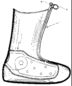
Figure 1 is a view if the device in one intended
use, namely a sport shoe with an inflatable bladder.
Figure 2 is an elevational view of the valve shown
in its housing, which is integral with the bladder pump.
Figure 3 is a cross-section of a prior art valve.
2a
CA 02357144 2009-05-11
51397-4
Figure 4 is a cross-section of a new deflation
valve which minimizes chance of inadvertent unseating of the
valve during use of the shoe.
2b
CA 02357144 2001-09-11
212/298
Figure 5 is a cross section of the deflation valve with
improvements to the valve stem.
Detailed Description of the Inventions
Figure 1 is a view of the device in a sport shoe with an
inflatable bladder. The shoe 1 may be any type of shoe, such
as a ski boot, snowboard boot, or basketball shoe. The shoe
has a bladder 2, which is located iri the shoe in positions
dependant on the use of the shoe. For example, the bladder
may be located on the tongue of shoe, on the uppers, the sole,
or around the heel. The pump 3 and the deflation valve 4 are
located in any convenierit: place on the shoe or boot, and they
are shown here located in the upper, high on the lateral side
of the shoe. To operate the pump, the wearer repeatedly
squeezes the pump until the desired degree of inflation is
achieved. To deflate the bladder, the operator pushes the
plunger on the deflatiori valve.
Figure 2 is an elevational view of the valve shown in its
housing, which is integral with the bladder pump. The bladder
pump 3 simply comprises a bulb 5, an inlet port 6 which takes
suction on the surround:_rig air or other fluid (and includes a
check valve so that flu:_d once sucked into the bulb cannot
exit this port), and an outlet port 7 (the outlet port also
includes a check valve So that air once forced out of bulb and
into the shoe bladder cannot bleed out of the shoe bladder and
into the bulb). The outlet port communicates with the T-
junction 8. The T-junction connects the bladder supply port
9, the pump outlet, and the deflation valve. The deflation
valve 4 has an input port in immediate fluid communication
with the bladder supply port through the T-junction, and an
output port through the opening on the top of the valve (more
fully shown in Figure 4.;
When operated by the user, the deflation valve allows air
from the bladder to exhaust to the atmosphere. The deflation
3
CA 02357144 2001-09-11
212/298
valve is operated by depressing the plunger 10, and holding
the plunger down until the air in the bladder has exhausted
through the valve. The pump and deflation valve assembly are
mounted on the shoe, as shown in Figure 1. As can be
appreciated from these cirawings, the plunger 10 is susceptible
to inadvertent operation since it requires only minor force to
operate, and the valve =-s located such that it is subject to
depression during inadve:rtent contact with objects, the ground
and ground debris, and the operator and equipment carried by
the operator.
Figure 3 is a crosES--section of a prior art pump and valve
assembly. As in Figure 2, the assembly comprises the bulb 5,
pump inlet port 6, pump outlet port 7, T-junction 8, and
bladder supply port 9. The deflation valve of the prior art,
as illustrated in Figure 3, uses a plunger 11 which
additionally comprises a plunger disk 12, valve stem 13, a
valve face in the form of ball 14, all within the valve body
15. The upper surface of the valve face is matched to the
valve seat 16, formed ori the lower surface of inner flange 17
which protrudes inwardly into the valve body. The valve
spring 18 biases the plunger upward, forcing the valve face
into contact with the valve seat with enough force to create
an airtight seal. The valve body arid flange are typically
made of silicon or other soft elastic material.
Figure 4 is a cross section of a new deflation valve
which minimizes the chance of inadvertent unseating of the
valve during use of the shoe. As in Figure 2, the assembly
comprises the bulb 5, pump inlet port (not shown), pump outlet
port 7, T-junction 8, and bladder supply port 9. The
deflation valve 4 compr:Lses a two part valve body, with a
lower valve body 23 made of a hard plastic, and an upper valve
body 24 made of similar hard plastic or other relatively stiff
and non-conformable material. The upper valve body is force
fit into the lower valve body and glued in place. The upper
4
CA 02357144 2008-07-11
51397'-4
valve body additionally comprises an inwardly protruding
flange 25, located at or near the upper end of the valve body.
The valve seat 26 is located on the lower surface of this
flange. The plunger 10 is relatively short, and does not need
a plunger disk on its upper extremity. At the upper end of
the plungerõ the plunger outer diameter is closely matched to
the inner diameter or bore of the flange 25, with clearance to
allow upward- and downward movement, but closely matched to
limit tilting and sideways_movement. At the bottom of the
plunger, a disk 28 provides a valve face 29 on the upper
surface of the disk and a bottom surface 30 upon which biasing
spring 31 may act. The plunger may include a lower extension
32 with a diameter smaller than the disk, closely matching the
inner diameter of the biasing spring 31, which will serve to
keep the spring and disk in vertical alignment and proper
registration. The biasing spring is located below the
plunger, and acts on the lower surface of the disk to force
the plunger upwardly. The biasing spring rests on a surface
provided by a flange or lower inner surface of the lower valve
body. The plunger is preferably made of metal or hard
plastic, and may generally be described as having a
cylindrical upper segment of a first, small diameter, a middle
segment of conical or_frustoconical shape having a maximum
outer diameter approximating the outer diameter of the spring
(but in any case not substantially smaller than the outer
diameter of the spring) and'a lower segment having a diameter
approximating the inner diameter of the spring. A soft,
deformable ring 33 is placed on the plunger, above the disk
28, to enhance the sealing capability of the valve. The
deformable ring may be fixed to the upper conic.al surface of
the plunger mid-section or it may be fixed to the lower
surface of flange 25, or it may merely be placed between the
plunger and the flange. This ring is made of silicon rubber
or similar soft, compliant material. This is particularly
useful in case of any tilting of the plunger. The valve is
5
CA 02357144 2008-07-11
51397-4
covered by a rubber condom or housing 34, and can be operated
by the operator through the rubber condom.
To operate the valve, the wearer merely pushes downwardly
on the plunger 10.. The close fit of the flange 25 around the
plunger permits upward and downward movement, but inhibits
side-ways or tilting movement of the plunger which would
otherwise permit deflation. Since the spring is located below
the plunger, and the valve seat is at the top of the valve,
the plunger does not need to be long enough to pass all the
way through the spring, thereby limiting the possible extent
of tilting of the plunger. Also, because the valve body is
made of hard plastic, deformation of the top of the valve body
relative to the bottom of the valve body is not possible with
the expected forces applied during snowboarding, skiing and
other rough activities.
Figure 5 is a cross section of the deflation valve with
improvements to the valve stem that ensure that the ring moves
downwardly with the plunger during operation. The valve
includes the parts described in relation to Figure 4,
including the lower valve body 23 and the upper valve body 24,
the valve body flange 25 and the matching valve seat 26, the
plunger 10, the disk 28 with its valve face 29'and bottom
surface 30, the spring 31 and the lower extension 32 of the
valve stem, and the deformable ring 33. The plunger has been
modified vis-&-vis the plunger of Figure 4 with the provision
of an annular groove 40 circumscribing the upper segment of
the plunger, near the junction of the upper segment 41 of the
plunger to the disk 28. The dimensions of the annular groove
are chosen to match the ring 33, such that the ring protrudes
into the groove to an extent that provides some engagement
between the upper segment and the ring, and downward movement
of the upper segment and plunger exerts a downward force on
the ring. The groove depth may be such that the resulting
diameter 42 of the grooved segment of the plunger is slightly
6
CA 02357144 2001-09-11
212/298
larger than the inner diameter of the ring, or it may be such
that the resulting diame:ter is exactly equal to the inner
diameter of the ring, or it may be such the resulting diameter
is smaller than the inner diameter of the ring and the
engagement between the plunger and the ring is loose in the
horizontal plane established by the groove. The longitudinal
extent 43 of the groove may likewise be variable, from heights
which are smaller than the height of the ring, exactly
matching the ring, or substantially larger than the ring, so
long as inward or downward movement of the plunger will result
in impingement of the groove upper surface on some portion of
the ring during some port:ion of the inward or vertical throw
of the plunger. (It should be noted that, in the above
description, the terms vertical and upward are used in
reference to the valve when positioried as shown, and they may
have no relationship to the vertical and horizontal as the
valve is fitted onto any particular boot.)
The devices described above have been described in the
context of sport shoes using inflatable bladders. However,
the deflation valve may be used with other selectively
inflatable devices, such as sport helmets, water flotation
aids, in medical devices such as dissection balloons, and in
any other application where enhanced reliability and control
over deflation of a selectively inflatable bladder is desired.
Thus, while the preferred embodiments of the devices and
methods have been described in reference to the environment in
which they were developed, they are merely illustrative of the
principles of the inventions. Other embodiments and
configurations may be devised without departing from the
spirit of the inventions and the scope of the appended claims.
7