Note : Les descriptions sont présentées dans la langue officielle dans laquelle elles ont été soumises.
CA 02357622 2003-06-20
CONCRETE RECOVERY SYSTEM
The present invention relates generally to the field of concrete
manufacture and more particularly to the field of recovery methods for
recycling
hydrated cement from returned concrete.
BACKGROUND OF THE INVENTION
Over the past decade, governments and environmental groups have
increased pressure on the ready-mix industry to reduce waste discharge. The
high-
pH, toxic, alkaline run-off caused by waste cement is now classified as a
hazardous
waste in some parts of the world and it is expected that the U.S. and Canada
will
soon mandate zero-discharge regulations for its ready-mix industry.
The problem is caused by hydrated cement, which contains Calcium
Hydroxide - (Ca(OH)2), the highly alkaline substance that acts as the binary
agent in
concrete. When Ca(OH)2 is released into the environment, it can be deadly to
fish
and wildlife and can potentially poison other public waterways. Ca(OH)2
created by
concrete production routinely exceeds the maximum allowed discharge pH levels
for
most civic process discharge permits.
Conversely, if recycled into fresh concrete without treatment, Ca(OH)2
can cause poor slump control, reduced strength and unpredictable finishing
characteristics. Once cement is exposed to water and hydration begins, it must
continue until the process is exhausted or suspended. The longer the hydration
period, the greater amount of Ca(OH)2 produced.
In recent years, chemical admixture producers have developed
hydration stabilization admixtures (HSA), which have provided the solution to
the
CA 02357622 2003-06-20
2
hydration problem of the cement. Since it is now possible to suspend hydration
for a
controlled period of time (stabilize), partially hydrated cement can be
recycled before
it entirely converts to calcium hydroxide through hydration. This also means
that a
portion of the cementitious value can be saved for later use.
Conventionally when a concrete mixer truck returns to the plant after
delivering a load, there is almost always unused concrete andlor residue
accumulated on the inside of the truck drum and chutes. The system delivers
chemically treated system-water to the truck drum to suspend hydration and
dilute
and rinse the drum contents into the close-circuit reclamation and recycling
system.
The process of hydration stabilization can be found in a technical
document named "A Novel Method Of Recycling Concrete Using Extended Life
Admixtures." Co-authored by Lawrence R. Roberts of W.R. Grace (Conn.) and
Seiji
Nakamura of K.K. Denka Japan, which was released at the European Ready-Mix
Association congress in 1998.
The term system-water may, throughout this document, also be
referred to as wash-water, washout fluid, slurry and batch slurry. It should
also be
noted, that throughout the course of this process description, when the system
transfers slurry from the recovery tank to the secondary tank, the
nomenclature used
to describe the slurry will change from "system-water" to "batch slurry". This
is
intended to clearly define the difference in the intended purpose of the
slurry in each
part of the process. The sand and gravel are classified out of the drum
contents
using, for example, a spiral-classifier re-claimer, while the cement and very
fine sand
report to the primary tank with the circulating system-water.
CA 02357622 2003-06-20
' 3
SUMMARY OF THE INVENTION
It is one object of the present invention to provide an improved method
for re-claiming and recycling cement into concrete production.
According to the invention, there is provided a method of recycling
waste unset concrete materials containing water, aggregates and partially
hydrated
cement, the method comprising:
providing a recovery tank;
introducing into the recovery tank water and hydration stabilization
chemicals to provide system water including a mixture of water and the
hydration
stabilization chemicals;
providing a plurality of transit mixer drums, each containing of waste
concrete;
for each transit mixer drum:
transferring from the recovery tank a portion of the system water from
the recovery tank into each transit mixer drum; ;
mixing in the transit mixer drum-the waste concrete and the system
water thereby forming an aggregate slurry;
transferring the aggregate slurry into an aggregate re-claimer so as to
separate the aggregate slurry into aggregates and slurry;
and transferring the slurry to the recovery tank to mix with the system
water to form a batch slurry;
providing a slurry supply system of a batching plant for supplying the
batch slurry in the recovery tank to a concrete batching plant for use of the
batch
CA 02357622 2003-06-20
s
4
slurry in mixing with aggregates and cement to form fresh concrete in the
hatching
plant;
and transferring the batch slurry from the recovery tank to the slurry
supply system for use of the batch slurry;
wherein separate portions of batch slurry from the recovery tank are
transferred to the slurry supply system through a transfer duct for use of
each
portion of the batch slurry at the slurry supply system;
and wherein each portion has the density thereof measured at the
transfer duct and, if necessary, changed in the transfer duct, such that each
portion
is supplied to the slurry supply system at the same constant density.
In order to transfer only batch slurry at the required density, the batch
slurry is returned to the recovery tank until the required density is reached.
In accordance with another important feature of the invention, the
water and hydration stabilization chemicals are introduced simultaneously into
the
recovery tank at a predetermined calculated ratio.
Preferably the predetermined ratio is determined based upon a target
density for the system-water in the recovery tank and preferably all the water
and
hydration stabilization chemicals are introduced at that set ratio while the
density is
at or below the target density. This allows a simple calculation and
adjustment and
control of the supply in that all materials are supplied at that same ratio
which is
determined by the target or intended density value even though the density may
to
reach that target until a number of recoveries have been made, following which
the
density is controlled by addition of further water and chemicals at the same
ratio.
CA 02357622 2003-06-20
For example, in order to keep cement hydration suspended for a period of 48 to
72
hours at a target density of 1.15 g/cm3 (20% solids by mass), HSA will need to
be
added to the water at a ratio of .002:1 or 2.00 liters of HSA for each 1000
liters of
water. If, alternatively, the density was 1.07 glcm3 (10% solids by mass), the
5 amount of HSA would change to .0015:1 or 1.5 liters of HSA for each 1000
liters of
water. These ratios will be scaled in accordance with temperature variations
in the
system-water.
In order to maintain that target density, the density of the system-water
is repeatedly measured and additional water and chemicals at the same set
ratio are
added when the density exceeds the target density to dilute the system-water
to
said target density.
The ratio may be calculated including as a calculation factor the
temperature of the system-water in the recovery tank and heating andlor
cooling
may be applied to the system-water to maintain the system-water at said
temperature.
In the event that the recovery tank is filled to capacity and the target
density is exceeded to an over density, additional chemicals are added without
additional water to provide a quantity of chemicals sufficient for said over
density.
In accordance with another important feature of the invention, there is
provided a sleep mode in which the slurry is to be left in storage for a
period of time
greater than a working period, in which mode additional chemicals are added
without
additional water at an amount dependent upon the time period beyond the
working
period. For example, if the density rises to 1.20 glcm3 (14% solids by mass),
CA 02357622 2003-06-20
6
chemical will be added according to the density based on the assumption that
the
tank is full and the chemical must be added in ratio to that full volume. Up
to and
including a density of 1.30 glcm3 (35% solids by mass) the system will add
chemical
at incremental intervals of one unit of specific gravity across the entire
volume of the
recovery tank.
The slurry supply system may include a batch tank dimensioned to
receive and store a batch of the batch slurry substantially equal to or
greater than a
required batch for the batch plant.
It is advantageous if the batch tank has a discharge for supply to the
batch plant which discharges the slurry at a rate greater than a rate of
supply thereto
so that the batch can be discharged rapidly into the batch plant for use while
the
batch tank can be re-filled more slowly using the transfer pump from the
secondary
tank to the batch tank.
Preferably the secondary tank is dimensioned to hold a quantity of the
batch slurry equal to or greater than a series of batches of the batch tank
for use of
the batch tank repeatedly during a work period, for example one shift or one
day,
and wherein the secondary tank is filled with the required amount of diluted
slurry
from the recovery tank for that period. For example, if the batcher requires
125 litres
per cubic meter of concrete, and he must batch 300 cubic meters over the
course of
a work period, then he will need to transfer 37,500 litres of batch slurry to
the
secondary tank during the work period to fulfil that requirement.
Preferably the batch slurry is stored at a temperature lower than a
required temperature for the concrete batching plant and is mixed with hot
water to
CA 02357622 2003-06-20
raise the temperature to the required temperature at or prior to the batching
plant. In
this arrangement the batch slurry can be diluted with hot water to effect
heating to
the required temperature and to effect reduction in density to the required
density.
BRIEF DESCRIPTION OF THE DRAWINGS
Two embodiment of the invention will now be described in conjunction
with the accompanying drawings in which:
Figure 1 is a schematic diagram of a first embodiment of the concrete
recovery system.
Figure 2 is a schematic diagram of a second embodiment of the
concrete recovery system.
Figure 3 is a side elevational view of the concrete recovery system
showing the arrangement of the components.
Figure 4 is a top plan view of the concrete recovery system showing
the arrangement of the components.
DESCRIPTION OF THE PREFERRED EMBODIMENTS
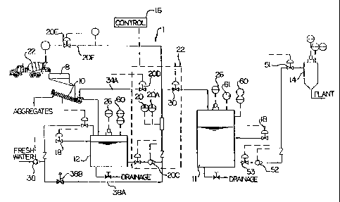
The embodiments shown in Figures 1 and 2 includes a concrete
recovery system 1 comprises: a conventional flume 8, a conventional aggregate
re-
claimer 10, a recovery tank 12, a secondary tank 11, a batch tank 14, a
control unit
16 including a dilution management assembly 22, a chemical supply 18 and a
batch
water supply 38.
The aggregate re-claimer 10 separates waste concrete mixture into
aggregate material and slurry. In some embodiments, the aggregate re-claimer
10
may be, for example, a gravity screw or trommel re-claimer with a de-watering
weir
CA 02357622 2003-06-20
and screw and may include the rinse flume 8, as described below. Other
suitable
arrangements may also be used, according to the manner in which the user
wishes
to recover aggregates. In some embodiments, the aggregate re-claimer 10
recovers
aggregate to 150 microns or #100 mesh in size or smaller.
The recovery tank 12 holds system-water and is connected to the
aggregate re-claimer 10 for supplying washing fluid for removing waste
concrete, as
described below. As described below, at the start of each cycle, the recovery
tank
holds water containing a hydration stabilization admixture (HSA). Initially,
this
mixture circulates through the aggregate re-claimer 10, acting as washout
water, as
described below. As trucks wash out, a density meter 20 and a temperature
monitor
20B in a discharge line 20A regularly monitors the density of the resulting
system-
water circulating from the tank 12 through the discharge pump 20C and an
irrigation
valve 20D. Over the course of the day, as the density of the system-water
rises, the
control unit 16 adds more fresh water from supply 38 and HSA from supply 18 in
order to maintain a target slurry density, as described below. In some
embodiments,
the solids in the system-water are kept in suspension in the recovery tank 12
with an
impeller agitator 24.
The secondary tank 14 stores the batch slurry for use in the
preparation of concrete. Specifically, system-water accumulated in the
recovery
tank 12 is pump-transferred to the secondary tank 11 for temporary storage
until it
can be re-used as batch slurry for mixing water in fresh concrete batches. In
use,
the batch slurry in the secondary tank 11 is transferred to batch tank 14 at
the batch
plant at the request of the batcher or system. In same embodiments, the
recovery
CA 02357622 2003-06-20
9
tank and the secondary tank 11 may each include an agitator 26, for example,
an
impeller agitator for keeping the slurry in suspension. In the first
embodiment
described herein, the batch slurry in the secondary tank 14 is transferred
from the
recovery tank at the same target density where it is stored at an elevated
density of
between 1.07 and 1.30 glcm3.
To effect transfer, the irrigation valve 20D and the giraffe valve 20E are
closed and a transfer valve 20F is opened simply acting to transfer all
materials
pumped by the pump 20C into the secondary tank 11 at the same density as the
target density in the recovery tank.
When required at the batching plant, the slurry is pumped from the
secondary tank 11 through the dilution management assembly 22 described below.
For example, the density required to batch maybe set at a lower density such
as
1.07 glcm3, although this may be set at different values depending upon the
batcher's requirements, which will require a fresh water to slurry water blend
of 1:1 if
the reservoir density is 1.15 glcm3 to as much as 4:1 if the reservoir density
is 1.30
g/cm3, as described below.
In the embodiment of Figure 1, the control unit 16 monitors and
maintains the density of the system-water in the recovery tank 12 and the
batch-
slurry in the secondary tank 11 and delivers the batch slurry at a
predetermined
density to the batch plant, as described below. A Coriolis density meter 20 is
installed on the slurry line to monitor the density of the batch slurry in
real time in the
re-circulation loop, as described below. As will be appreciated by one
knowledgeable in the art, other suitable density meters known in the art may
also be
CA 02357622 2003-06-20
used. The density meter 20 feeds back to a PLC control system that will
monitor
and adjust the system settings to allow proper blending, as described below.
An
Operator Control Panel is installed at the batch station to allow the batcher
to
monitor the system and make periodic adjustments as may be required to reflect
the
5 changing needs of the user.
The dilution management assembly 22 in some embodiments is placed
as close to the batch plant as possible. In one embodiment, the assembly sits
atop
a metal platform 50 that is approximately 10 to 12 feet in length and 4 to 6
feet in
width. As shown in Figure 1, the secondary tank 11 is connected to a batch
slurry
10 feed line 27 and a circulation loop 34. There is a "Y" valve 25 that allows
the slurry
feed line 27 and fresh water feed line 23 to flow into a common line 26, as
described
below. The common line 26 following the "Y" valve 25 is in one embodiment
approximately 5 feet in length to allow the diluted batch slurry to settle
from a
turbulent flow to a laminar flow. The common line 26 is connected to the
density
meter 28, as shown in Figure 2. Downstream pipe 29 exits the density meter 20
and
is connected via pipe 27 to return valve 32 that leads to the secondary tank
11. The
downstream pipe 29 is connected to a discharge valve 30 that allows the slurry
to
report to the batch water weigh hopper 14. In other embodiments, the batch
slurry
may be introduced into the batch process using a flow meter rather than a
weigh
hopper. It is of note that when the discharge valve 30 is open, the return
valve 32 at
the head of the return line to the secondary tank 11 closes. These two valves
operate opposite one another, so that the return loop and the batch weigh
hopper
delivery line will remain independent, allowing the proper dilution to be
established
CA 02357622 2003-06-20
11
into the lop before the valve 30 is opened to allow the properly diluted
slurry to flow
to the batch tank 14.
In use of the first embodiment, before the commencement of
operations on any given day or as required by the producer, the recovery tank
12
has added thereto an initial quantity of water and a corresponding amount of
HSA.
The principle of chemically stabilizing cement is based on the use of a
carboxylic
acid to suppress hydration activity for a defined period of time. This is
accomplished
by adding a specific quantity of HSA to a known quantity of water in which
cement
particles will be suspended for an established period of time. The purpose of
the
specific quantity of HSA is to stabilize the cement hydration for a finite
period of time.
In most cases, the cement will require stabilization for 12-24 hours. Further
detail on
the process of hydration stabilization can be found in the above mentioned
technical
document named "A Novel Method Of Recycling Concrete Using Extended Life
Admixtures." Co-authored by Lawrence R. Roberts of W.R. Grace (Conn.) and
Seiji
Nakamura of K.K. Denka Japan, which was released at the European Ready-Mix
Association congress in 1998. A transit mixer 22 backs to the rinse flume of
the
aggregate re-claimer 10 to discharge waste concrete remaining in the mixer
drum of
the transit mixer 22. The operator depresses a water delivery button at the
aggregate re-claimer 10 that causes water from the recovery tank 12 to be
pumped
via, for example, a giraffe pipe into the transit mixer drum. The water and
waste
concrete is then mixed at high speed for a period of time, for example, two
minutes,
thereby forming an aggregate slurry. The aggregate slurry is then discharged
into
the aggregate re-claimer 10.
CA 02357622 2003-06-20
12
The aggregate re-claimer 10 removes all aggregate material larger
than 150 microns from the washout, for example, by means of a gravity de-
watering
screw or trommel re-claimer, and discharges the aggregate into aggregate
bunkers
for eventual return to stockpile. Thus, reclaimed aggregates can be screened
to
their original classifications and returned to stockpile at full value. The
aggregate re-
claimer 12 is able to recover fines down to at least 150 microns or smaller,
leaving a
slurry with a cementitious to non-cementitious ratio of fines ranging from
70:30 to
90:10.
It is desirable to remove as much of the non-cementitious fines from
the aggregate slurry as possible. Reduction of coarse and non-cementitious
fines
reduces abrasion wear, extending the life of the components of the concrete
recovery system 1 and allows for more efficient use of chemical stabilizer and
greater system capacity for storage of more valuable cement and fly ash.
The system water/slurry is then discharged to the recovery tank 12
until needed for subsequent washouts. A density meter 20 regularly reports the
density of the system-water in the recovery tank 12 to the control unit 16.
Based on
the user's system settings, the control unit 16 may periodically add more
water
andlor HSA as the density of the system-water rises.
Thus, over the course of the production day, the density meter
monitors the rise of solids in the slurry. If the percentage of solids rises
above a
preset limit, an additional draft of water will be pumped into the tank with a
corresponding amount of HSA. As discussed above, the goal is to keep the
density
of the system-water at a target limit.
CA 02357622 2003-06-20
13
If high volumes of washout cause the system-water solids to continue
to rise after the design volume capacity limit of the system has been reached,
further
HSA will be added according to the solids increase, but not water. This
guarantees
that the cement in the slurry will remain uniformly stabilized for the time
that it is
required to remain in storage.
When the production day is complete, the control unit 16 automatically
transfers the slurry from the recovery tank 12 to the secondary tank 14.
Alternatively, the user may choose a specific time or set of conditions when
the
control unit 16 will automatically transfer slurry from the recovery tank 12
to the
secondary tank 14. When the batcher requests batch water far process mixing,
it is
drawn from the batch tank 14 instead of from a fresh water source. When the
batcher asks the system to deliver slurry to the batch tank, water weigh
hopper or
through a flow meter to the batch process, the system 1 immediately begins a
dilution cycle to reduce the density from the higher values in the secondary
tank 11
to the lower values required at the batch plant. This is initiated by a real
time density
measurement to determine if the density is above or below the target value
required,
as described below. If the density exceeds the target value allowed by the
hatching
process, the system 1 will instruct a fresh water valve 40 to open to begin
diluting
the batch slurry. As the valve 40 opens, the slurry line will begin to accept
fresh
water until the density reaches the target batch density, at which point the
discharge
valve 30 will open and the diluted batch slurry will be discharged to the
batch tank
14, water weigh hopper or flow meter. When the appropriate amount of batch
slurry
has been delivered, the discharge valve 30 will close and the fresh water
supply will
CA 02357622 2003-06-20
14
be terminated. The batch slurry will then continue to circulate until the
batcher calls
for more dilute slurry to batch. It is of note that the slurry water is
delivered to the
batch plant at a controlled predetermined density, preset by the operator and
programmed into the control unit 16. Solids in the batch slurry are
compensated for,
by adjusting mix designs to allow for reduction of fresh ingredients and
addition of
slurry solids.
It is of note that the slurry dilution cycle may be initiated by the batcher
or by a tank level indicator in a batch tank 14 that asks the system 1 to
automatically
refill the batch tank 14 if it drops below a certain volume level. However
that supply
is always at the predetermined density due to the controlled inline dilution
from the
higher density of the slurry stored in the secondary tank 11.
The actual step by step procedure of diluting the stored batch slurry to
batch density is as follows. When the batcher starts the slurry re-circulation
loop, a
re-circulating valve 44 is open and the meter valve 25 is closed, so that the
batch
slurry flows along a circulation loop 34back to the tank 11. Next, the system
1
closes re-circulating valve 44 and discharge valve 30 and opens meter valve 25
and
return valve 32. As a result of this arrangement, the batch slurry will pass
through
the dilution management assembly 22 for a period of time sufficient to
determine the
density and temperature of the batch slurry. Once density and temperature have
been established, the system 1 will update agitator speed and sets the slurry
transfer pump speed to reflect the rate that the un-diluted slurry is
delivered to the
dilution management assembly 22. This rate is consistent with the ratio of
blending
that will be required to reduce the batch slurry from its storage density to
the batch
CA 02357622 2003-06-20
' 15
density. Once agitator and pump speeds have been set, the system 1 closes the
meter valve 25 and the return valve 32 and opens the re-circulating valve 44.
As a
result of this arrangement, the batch slurry returns to re-circulating loop 34
and the
system 1 awaits the next command from the batcher. When the batcher or the
system 1 calls for batch slurry to be delivered to the batch tank 14 or flow
meter, the
system 1 closes the circulating valve 44 and the discharge valve 30 and opens
meter valve 25 and return valve 32. The variable frequency drive on the batch-
slurry
transfer pump motor then increases or decreases pump speed to control the rate
of
slurry delivery to the dilution management assembly 22. For example, when
using a
peristaltic (hose) pump as a batch slurry transfer pump, the fresh water to
batch
slurry water ratio is determined by a system preset. For example, if the
stored batch
slurry in the tank has a density of 1.15, the system will require
approximately a 1:1
ratio of fresh water to batch slurry water to dilute the batch slurry to 1.07.
Therefore,
if the batch slurry transfer pump is set to deliver 100 gallons per minute to
the batch
tank 14, the fresh water valve 40 will also deliver 100 gallons per minute,
providing a
total flow of 200 gallons per minute of batch slurry diluted to 1.07. In a
different
scenario, where the stored batch slurry in the secondary tank 11 is at a
density of
1.30, the fresh water to batch slurry ratio will be 4:1, in which case the
batch slurry
transfer pump will be set to deliver 40 gallons per minute to the dilution
management
assembly 22, while the fresh water valve 40 will deliver 160 gallons per
minute to the
dilution management assembly. This will also provide a total flow of 200
gallons per
minute of batch slurry diluted to 1.07. It is of note that in some
embodiments, the
batch slurry transfer pump will have not less than four possible speeds of
slurry
CA 02357622 2003-06-20
16
delivery to accommodate four different batch slurry densities. Small
variations in
batch slurry density between the set points will be compensated by real time
adjustments in the fresh water flow rate. As the batch slurry and fresh water
converge and flow into the density meter 20, the density of the diluted batch
slurry is
monitored and reported back to the system 1. If the density is above or below
the
batch target density, the fresh water valve 40 will open or close to bring the
density
into a target range, typically between 1.069 glcm3 and 1.075 g/cm3 if the
target
density is 1.07 glcm3. Once the batch target density has been reached, the
system
1 closes return valve 32 and opens discharge valve 30. This allows the batch
slurry
to report to the batch tank 14. The flow will continue until the batch tank 14
records
a full reading and instructs the system 1 to return to re-circulation, or
until the
batcher has received enough diluted batch slurry in the weigh batch hopper 14
and
instructs the system 1 to stop delivering batch slurry. Once the system has
stopped
delivery of batch slurry to the weigh batch hopper 14, the settings of the
dilution
management system 22 will be recorded in a PID loop that will instruct the
system to
return to its last known delivery settings the next time batch slung is called
to batch.
This will reduce the time required to find the exact batch target density to a
few
seconds rather than 15 to 30 seconds.
If the system 1 requires hot water to compensate for cold weather
aggregate temperatures, the dilution management system can use hot water as
its
fresh water feed source, eliminating the need to blend several water sources
to
arrive at a suitably blended batch slurry temperature and density, or can use
a hot
water heat source as shown in Figure 1.
CA 02357622 2003-06-20
17
The primary function of the concrete recovery system 1 is to safely and
efficiently recycle cementitious slurry water. In order to accomplish this, it
is
necessary to develop a consistent and carefully controlled method of
incorporating
slurry into the hatching process. The key to accomplishing this is to maintain
a
constant regular density for all recycled slurry water. The in-line dilution
and mixing
process dilutes a stream of cementitious slurry with fresh water in flow,
arriving at a
target density that will be both consistent and reliable. This constant supply
of slurry
at a stable target density allows the ready-mix producer to use the slurry
water as
mixing water for manufacturing fresh concrete. Furthermore, the stability of
the
slurry density acts as a quality control constant, providing consistently
similar
performance characteristics of the fresh and hardened concrete. Maintaining
regular
density allows the producer to develop mix designs for use of the slurry that
are
constant and reliable in both placing characteristics and final strengths. It
also
allows the producer to balance the amount of slurry accumulated over a given
day
with the amount distributed over the following day's production. This
balancing of
intake and outflow will assists in guaranteeing quality control. By
eliminating the
need to calculate the blending ratios, the system is as close to fail safe as
can be
expected. In this regard, the discharge valve 30 must remain closed until the
density
meter 20 reads that the diluted batch slurry density has reached the target
range
and is ready to be released. From a batcher's standpoint, the system frees him
from
having to modify mix designs to compensate for fluctuating densities, and
practically
eliminates the risk of liability associated with concrete failures due to
error in
compensatory calculations by the batcher.
CA 02357622 2003-06-20
18
Thus, the concrete recovery system is an aggregate re-claimer and
slurry recovery system that operates on a closed circuit, zero-discharge
principle,
and can be implemented as a parallel system with any ready-mix batch plant.
The
system reclaims aggregates for re-use and recovers cementitious slurry for re-
use
as process mixing water, as described below. The system combines density
management with chemical hydration stabilization in a self-monitoring and self-
regulating storage and transfer environment. The fundamental goal of the
system is
to return the batch slurry to batch at a controlled density, allowing the
cementitious
solids in the batch slurry to be recovered as replacement material for fresh
fly ash or
cement.
In practical terms, when the batcher calls for batch slurry, it is delivered
to the batch plant at the preset density. This density will correlate with the
slurry-
based mix design written into the batch computer. The underlying principle is
to
maintain exactly the same batching procedure as would be followed under normal
circumstances. The only difference is that part of the cementitious material
is
supplied with the slurry, allowing the operator to reduce the cement andlor
fly ash
called for in the mix design.
For example, a normal Portland 25 MPa mix design calling for:
215 Kg cement
70 Kg fly ash
105 Kg fresh water
Could be replaced with a mix design calling for:
210 Kg cement
CA 02357622 2003-06-20
19
65 Kg fly ash
116 Kg slurry at a density of 1.07
In another configuration for example, in which the concrete producer
chooses to simply dispose of the cementitious slurry solids in the fresh
concrete
batches, he may choose not to modify the mix designs, but rather let the
slurry solids
be added to the fresh mix in addition to the normal distribution of the
constituent
ingredients and allow the final strength to be over-designed and the benefit
to carry
forward to the concrete purchaser.
In all other respects, the mix design would be identical to a normal
production design, and since the cement slurry is stabilized, it will not
affect other
admixture relationships in the fresh batch such as air entrainment.
Turning now to the second embodiment shown in Figure 2, this is
modified from the first embodiment by a number of features, the primary one of
which is that the control of the dilution of the batch slurry to the required
density
occurs between the primary tank and the secondary tank so that the required
amount of batch slurry for a period of use, typically one day or one
production cycle,
is stored in the secondary tank at the required density and can be supplied at
that
density on demand to the batching system. Thus an additional fresh water line
38A
from the supply 38 is connected through a valve 38B to the output from the
pump
20A for mixing with the slurry from the tank 12. The return loop 34A for
establishing
the required dilution is formed through the irrigation valve 20D following
which the
valve 20D is closed and the valve 30 opened to transfer the accurately diluted
slurry
to the secondary tank 11. Transfer from the tank 11 to the batch tank 14 is
effected
CA 02357622 2003-06-20
through valves 53 and 51 and pump 52.
The following is a detailed description of the second embodiment,
which may repeat some aspects which are common to both embodiments.
The trucks will receive system-water for drum rinsing through giraffe
5 transfer pipes 20F and valve 20E at each truck station. They will discharge
the
waste concrete mixture or aggregate and slurry into an intake flume with
internal
rinse irrigation. The flume will provide for quick discharge of aggregate and
slurry
and controlled feed into the re-claimer. The coarse aggregate is classified
out of the
drum contents by means of a 36" x 25' spiral-classifier and discharged into a
storage
10 bunker, while the cement, low-density fines and water flow into the primary
tank in
slurry form.
The principal storage and transfer component of the system are: two
API 650 storage tanks 12 and 11 mounted on a rigid skid-frame 50 located at
the
washout transfer station and one (1 ) batch tank 14 located at the plant. The
system
15 is delivered as a complete unit ready for use, with operating components
fixed to the
skid-frame. It may be installed quickly and efficiently without disrupting
plant
operations.
The API 650 tank capacities can be expanded with flanged sections to
extend nominal tank height from a base design of 9' 6" up to 14' 6" or even as
high
20 as 19' 2". The tanks 11 and 12 are fitted with agitators 26 to maintain
controlled
homogeneity of the contents. The three standard tanks are designated as
follows:
The recovery tank 12 holds a maximum 34,500-liter volume of system-
water containing a hydration stabilization admixture (HSA). This system-water
CA 02357622 2003-06-20
21
circulates through the washout transfer station and re-claimer providing rinse
water
for the trucks 22 and irrigation water for the re-claimer 10.
The secondary tank 11 holds a maximum 55,250-liter volume of batch
slurry in temporary storage until it can be re-used as mixing water in fresh
concrete
production.
The 1,720-liter batch tank 14 automatically receives batch slurry from
the secondary tank to maintain a just-in-time volume of batch slurry for use
in fresh
concrete mixes as required by the batcher. The recycle water port on the batch
computer actuates the discharge valve on the batch tank.
The process equipment and system instrumentation is mounted on the
skid andlor affixed to the tanks as required. This includes the following:
All tanks are fitted with agitators 26 and tank baffles to keep solids in
proper suspension. The agitators are hydrofoil-impellers that provide maximum
homogeneity with minimum shear abrasion.
The primary pump 20C delivers system-water to the truck drums 22
for rinsing and irrigates the re-claimer 10 and flume 8 to wash the waste
concrete
mixture into the system. The primary pump 20C transfers system-water from the
recovery tank 12 to the secondary tank 11.
The secondary pump 52 delivers batch-slurry from the secondary
storage tank to the batch tank at the plant for use as mixing water in fresh
concrete.
An in-flow density meter 20 monitors system-water/batch slurry density
and temperature. The information is used to control system-water/batch slurry
density and temperature management and the transfer-dilution process.
CA 02357622 2003-06-20
22
A service 38 for fresh water addition is mounted to the skid-frame 50
consisting of a flow meter and automated control valve.
All piping and fittings are schedule 40 with long radius elbows to
reduce abrasion. All process control valves are high quality, 150-p.s.i.-rated
pneumatic pinch valves with replaceable rubber sleeves.
All tank volume levels and high-low signals are monitored and reported
to the system controls by an ultrasonic level sensor and transmitter 60. This
gives
the batcher a visual graphic and corresponding numeric value at the batch
plant
indicating the volume and level in each tank and triggers automated system
activities.
The recovery tank monitors temperature at the density meter 20, while
the secondary tank is fitted with a thermal sensor 61 to monitor batch slurry
temperature. These sensors can be used to interface with a heat exchanger or
other variety of heating or cooling system (not shown).
A chemical addition system 18 automatically injects HSA into the
system-water and is designed to feed chemical into both tanks as the system
demands.
The dilution management system uses fresh or process water to dilute
the recovery tank system-water to a constant density in transfer to the
secondary
tank, thereby guaranteeing a stable supply of batch slurry in the secondary
tank at
the density required to batch without manual calculation or risk of error.
The system management controls package ties the process equipment
and controls into an integrated automation system. The system monitors,
controls
CA 02357622 2003-06-20
i
23
and maintains the system-waterlbatch slurry in storage and delivers it at a
predetermined density to the batch plant.
An operator control panel (OCP) 16 is installed at the batch station to
allow the batcher and quality control personnel to monitor the system and make
periodic adjustments as may be required to reflect the changing needs of the
producer.
When batching with batch slurry , the goal of the system is to provide
the batcher with a stable supply of batch slurry at a constant density and
also a
constant temperature as required by the producer. This allows the batcher to
use
most existing batch computers to adjust or modify the final batch outcome.
If the user wishes to increase secondary storage density and dilute the
slurry in the weigh hopper, the batch computer can be preset to add make-up
water
to a draft of recycled water to reduce density at the weigh hopper. This
method
expands the storage capacity of the system by allowing the secondary tank to
store
more slurry solids.
For example, if the storage density in the secondary tank and transfer
circuit were set at 1.10 glcm3, the batch computer could be set to
automatically add
make-up water to the slurry in the weigh hopper to reduce its density to 1.07
glcm3
by splitting the feed of slurry in ratio to fresh water at 1:0.6 or 60% slurry
and 40%
fresh water.
In winter batch-slurry can be stored at a relatively high density and at
low temperature and diluted with hot water in the batch weigh hopper. This can
be
used to elevate batch-slurry to high temperature seconds prior to delivery,
allowing
CA 02357622 2003-06-20
24
heating of the slurry without propagating hydration across the stored volume
in the
secondary tank or allowing high-temperature initiated hydration to continue
long
enough to have any noticeable effect on the fresh concrete. The low
temperature
storage reduces the amount of chemicals required as hydration is temperature
dependent. In the alternative, the mixing with hot water can be combined with
the
dilution step.
Each washout station is fitted with a 3"-diameter, giraffe-style overhead
water-transfer pipe to deliver system water to the mixer drum. Each giraffe
assembly is fitted with a user switch box with two (2) safety designed, all-
weather
push buttons, an open/close pinch valve and a flow meter. The start buttons
will be
clearly marked FULL RINSE and CHUTE RINSE.
The wash stations are positioned along a common collection flume into
which the waste concrete mixture is discharged. A fresh-water hose will be
mounted
at each giraffe to facilitate manual truck chute rinsing. HSA will be injected
into this
rinse hose to maintain overall chemical balance during un-metered additions of
rinse
water (i.e. rinsing chutes and truck components).
Depressing the Full Rinse button will initiate delivery of a draft of
system-water from the recovery tank to the truck drum. The draft quantity is
user-
defined (nominal 1000 liters). The chemical present in the slurry will coat
the truck
drum, aiding resistance to build-up of waste concrete. System-water will
dilute the
waste concrete mixture , making it flow-able and easily discharged. The end of
the
drum transfer cycle will initiate an irrigation cycle. Irrigation cycle time
is user-
defined (nominal 16 minutes). System-water conditions will be monitored during
the
CA 02357622 2003-06-20
irrigation cycle allowing system settings to be updated. If a full rinse cycle
is in
progress when a new driver depresses the Full Rinse button at his particular
station,
the system will restart the cycle.
Depressing the Chute Rinse button will initiate an irrigation cycle
5 without a drum transfer by controlling the valves 20D and 20E.
Irrigation cycle time is user-defined (nominal 3 minutes). A rinse hose
will provide chemically treated fresh/process water to rinse chute washout
into the
re-claimer. System-water conditions will be monitored during the irrigation
cycle,
allowing system settings to be updated. If a full rinse cycle is in progress
when a
10 new driver depresses the Chute Rinse button, the system will restart the
cycle.
As multiple-serial transfer valves open or close, line pressure will rise
and fall. The system senses the pressure change and adjusts the primary pump
20C speed and flow rate to maintain a constant transfer flow rate regardless
of the
number of open valves. This will guarantee constant transfer times. The Full
Rinse
15 button starts the primary pump, opens the giraffe valve and delivers 1000
liters of
system-water to the truck drum. When the drum transfer flow meter registers
the
complete transfer of system-water, the giraffe valve will close and the
irrigation valve
for the re-claimer will open. The re-claimer begins operation when irrigation
valve
opens. The irrigation system runs on a timer for 16 minutes and then
automatically
20 shut down the primary pump and re-claimer when the cycle is complete.
The Chute Rinse button starts the primary pump 20C and the re-
claimer without transferring system-water to the truck drum. The Chute Rinse
button
CA 02357622 2003-06-20
26
initiates a 3-minute rinse cycle through the re-claimer irrigation system. The
end of
the rinse cycle will cause the re-claimer and pump to shut down.
The operation of the re-claimer and flume will always be in conjunction
with irrigation flow provided by the primary pump. Flow will be divided
amongst the
flume and re-claimer at a nominal flow rate of 600 liters per minute.
For example, a spiral-classifier, which employs a rising current
classifier provides for efficient removal of low-density cementitious and sand
fines
while allowing heavier aggregate to sink to where the spiral can remove it
from the
re-claimer. A wash back channel in the spiral-classifier provides further
irrigation by
rinsing the spiral channel to keep it clear of accumulated fines.
The intake flume is fed with system water through rinse piping that will
flush the waste concrete mixture into the re-claimer. The primary pump feeds
the
flume to maintain material recovery and separation at optimum efficiency.
The recovery tank has three principal functions. They are:
a reservoir for system-water used to irrigate on the re-claimer and
provide rinse water for the trucks;
collection and storage vessel for cementitious and sand fines collected
in the washout process; and,
the point of chemical stabilization for incoming cementitious material.
The recovery tank has a nominal volume of 34,500 liters or 9,100 U.S.
gallons. It is fitted with a ULI and an in-flow density meter in its
irrigation piping.
The recovery tank and re-claimer circuit have three possible operating
CA 02357622 2003-06-20
27
modes. The parameters are user specified to reflect the needs of the producer.
The
modes are:
Target-Density Mode (TDM) - In TDM, the nominal density of the
system-water ranges between 1.00 to 1.15 glcm3., and the system strives to
maintain minimum volume at a constant density near the high end of that range.
As
solids enter after the high end of the range has been reached, dilution water
and
hydration stabilization admixture will be added to the tank at the pre-
calculated ratio
determined by the target density and the temperature to reduce the system-
water
density below the high end of the range and maintain the proper chemicai/water
ratio.
High-Density Mode (HDM) - In HDM, the nominal density of the
system-water may rise as high as 1.30 glcm3 In HDM, the system disallows
addition
of fresh dilution water, but allows addition of HSA in proportion to
temperature and
density. Solids continue to be accepted by the system during HDM, but the
system
requests the batcher to transfer system-water to the secondary tank to allow
return
to TDM.
Sleep Mode (SM) - SM can be initiated by the batcher or automatically
at a preset time. SM will start a system clock to monitor the age and
temperature of
the slurry with user-defined, periodic 3-minute irrigation cycles and timed
system
commands. The primary function of SM is age monitoring and HSA addition, which
is tied to temperature changes in the system-water and batch slurry or a
preset
elapsed time limit on the system clock. If sleep mode continues unbroken for
the
length of the preset timed-cycle, the system will add chemical according to
the
CA 02357622 2003-06-20
28
volume, temperature and density of the system-water and/or batch slurry, and
return
the preset timer to zero to begin a new cycle. In SM, a gate valve 53 between
the
secondary tank and the batch tank will close, preventing slurry solids form
migrating
into the secondary transfer pump casing and also acting as a security
precaution
against spillage in the event of a seismic event. Furthermore, the isolation
of the
secondary transfer line from the secondary tank will allow the secondary
transfer line
to be purged with fresh water and then drained to prevent pipe rupture or
unnecessary accumulation of solids in the transfer line during long system-
idle
periods.
The fill cycle is automatic with manual override. Flow meter monitors
the fresh water inflow volume. HSA is added automatically with fresh water at
the
pre-calculated ratio. Re-fill of the tank is triggered by low-level signal.
The control of the recovery tank transfer process may be done
manually as required. If the transfer causes complete evacuation of the
recovery
tank, the end of the transfer cycle will trigger the beginning of a new fill
cycle. When
the tank level drops below a preset minimum, the system may automatically
dilute
and transfer the remainder of the recovery tank 12 contents to the secondary
tank
11 or, alternately, trigger a warning signal to inform the batcher to transfer
the
remaining volume manually at the batcher's convenience.
The system monitors system-water density and temperature condition
during each irrigation cycle. In SM, a periodic user-defined irrigation cycle
monitors
and corrects system-water condition. Dramatic changes in conditions can
trigger
alarms to notify service personnel.
CA 02357622 2003-06-20
29
The system controls operation of an HSA system to inject chemical to
the recovery tank as required. In TDM, HSA is added in ratio to fresh water
inflow
volume, temperature adjusted between 4°C and 38°C. In HDM, HSA
is added in
ratio to system-water density and the measured volume of the recovery tank,
temperature adjusted between 4°C and 38°C. In SM, HSA is added
in ratio to
density in the measured volume of the recovery tank, adjusted by slurry
temperature
between 4°C and 38°C.
For Storage Target Density & Dilution, the density meter has a read-
out to four decimal places. Target density setting is adjustable from 1.0000
glcm3 to
1.3000 glcm3. The target density setting has a threshold of one digit in the
second
decimal place above and 2 digits below the target density (e.g. If target
density is
1.1500, dilution commences when the density reaches 1.1600 and ceases when
density drops to 1.1300 or below). The system will not dilute until the
recovery
circuit is idle. System locks out washout station and re-claimer during
dilution.
The system is arranged to provide a Transfer Target Density and to
effect Dilution from that target density during transfer from the tank 12 to
the tank 11,
for this purpose, recovery target storage density will always be higher than
secondary target batch density. This will always require some degree of
dilution as
slurry is transferred from the recovery to the secondary tank. As the transfer
cycle
begins, the system will check the slurry density in the transfer line and
begin to
introduce fresh dilution water to reduce the storage density in-flow to the
batch
density. The transfer valve 30 will open at the target batch density and allow
batch
CA 02357622 2003-06-20
~s
slurry transfer to the secondary tank. Storage density and batch density can
be
user-defined.
In the fill cycle, when the ULI senses that the recovery tank 12 volume
has dropped to its minimum level, an automatic refill cycle will commence if
the last
5 recorded density measurement is above 1.10 glcm3. The cycle will begin with
a
purge transfer of the final volume in the recovery tank. The procedure is as
follows.
The system will check the level in the secondary tank 11 to ensure there is
sufficient
capacity to accept the final transfer. If capacity is sufficient, slurry will
be diluted and
transferred to the secondary tank and refill will commence. If capacity is
insufficient,
10 the system awaits override by the batcher or notice of available capacity
from the
secondary tank ULI. While the system is awaiting override or notice, a
transferlpurge
signal flashes on the OCP screen to notify the batcher of the impending
transfer.
When capacity becomes available, dilution-transfer and refill will
commence. The batcher can manually dismiss the transfer notice and return the
15 recovery circuit to normal operation. This manual-dismiss command will
cause
addition of fresh water and a corresponding quantity of chemical to bring the
recovery tank volume to a preset level above the minimum level. Each time the
recovery tank volume drops below the preset level it will trigger a transfer
notice.
During the final volume dilution and transfer, the ULI monitors the tank
20 levels. When the volume remaining in the tank reaches 100 gallons, the
density
measurement and dilution will cease. The secondary transfer line will remain
open
and the pump will, for example, continue to transfer for 60 seconds. Fresh
water
induction valve commences refill process. When the period ends, the transfer
valve
CA 02357622 2003-06-20
31
closes and the pump stops, but the fresh water service continues to fill the
tank.
Flow meter commences to measure fresh water inflow. The flow meter will
totalize
the fresh water volume inflow until the recovery tank reaches the preset
minimum
metered volume at which time the fresh water fill valve will close. The
closing of the
fresh water fill valve will trigger the start of a 3-minute chute rinse
irrigation cycle.
The irrigation cycle will allow the system to determine density and
temperature. The
temperature and metered water volume determine the amount of chemical added to
the fresh water. The density measurement resets the agitator speed. The rinse
cycle ends switching off the pump and closing all recovery and transfer
valves.
The Agitator 26 speed is controlled by the PLC to correlate system-
water density with impeller speed. As the density fluctuates, so does agitator
speed.
The agitator 26 will automatically switch off when the level in the tank drops
below a
preset limit. Conversely, when the level rises above the preset limit, the
agitator will
recommence operation.
A dilution cycle begins when the density in tank 12 rises .01 g/cm3
above the target setting. The re-claimer and wash station valves 20D and 20E
are
locked out. The system transfers 2000 liters of fresh water into the tank.
Chemical
is added at the pre-calculated ratio according to volume and temperature of
fresh
water. The addition of chemical is recorded and totalized. A chute rinse cycle
will
commence to measure density. If density is below 1.13 glcm3, system moves to
next step. If density is above 1.13 g/cm3, system adds more dilution water and
chemical. Dilution sequence repeats until the desired target density is
reached. The
re-claimer and wash station valves 20D and 20E will be unlocked.
CA 02357622 2003-06-20
32
When the ULI senses that the recovery tank has reached maximum
allowable volume at the target storage density, recovery tank controls will
switch to
HDM. Switching to HDM mode will commence a transfer-warning signal at the OCP
to advise the batcher to transfer a quantity of system-water to create
capacity in the
recovery tank for further dilution and addition of washout solids. The
transfer
warning will continue until the batcher transfers enough volume to the
secondary
tank to terminate the HDM. In HDM, dilution water is no longer added as
density
rises. The system monitors density and temperature during HDM and adds
chemical according to an HDM I chemical addition scaling function. This will
automatically determine the amount of chemical to be added according to the
density modified by temperature.
As required by the batcher, system-water is transferred to the
secondary tank in quantity sufficient for the batching requirements for the
period
concerned, which may be dailylhourly and the system-water then becomes batch-
slurry. The batcher inputs a transfer quantity into transfer screen on OCP.
The
transfer command is initiated, causing the system to lockout all other
functions. The
primary pump 20C starts, allowing the density meter to read the system-water
density and commence dilution. The fresh water valve 38B will open until the
density measured by the density meter reaches the target batch-slurry density.
The
transfer valve will open causing the dilute batch-slurry to be transferred
into the
secondary tank. The transfer will continue until the volume transferred
reaches the
quantity input by the batcher in step 2 above.
The transfer valve closes and the system returns to idle.
CA 02357622 2003-06-20
33
When the batcher requires system-water to be transferred to the
secondary tank for storage as batch slurry, the dilution-transfer command will
allow
controlled density system-water to be transferred from the recovery to the
secondary
tank. The secondary tank 11 will store and monitor the condition of the batch-
slurry
in the secondary stage before it is sent to the batch plant for use as mixing
water.
Volume and capacity are monitored and displayed at the OCP. Temperature and
density are monitored and displayed at OCP. Batch slurry age is monitored
while
system is in sleep mode.
The transfer pump delivers the batch-slurry to batch tank. Transfer is
automatically initiated by the level indicator in batch tank.
For Hydration Stabilization, a user-defined slurry-age timer counts
down to re-dosage when the system is in sleep mode. HSA is added automatically
to prolong the cementitious life of the batch slurry and prevent hydration
from
recommencing.
The batch tank holds a just-in-time volume of batch-slurry for delivery
to the weigh hopper at the batch plant. The batch tank has an agitator to keep
solids
in suspension. The batch tank has a ULI to monitor tank batch-slurry volume.
The
batch tank refills automatically when volume drops below a preset level. The
recycled-water port on the batch computer controls the batch tank discharge
valve.
The density of the batch-slurry in the secondary tank will control the
agitator speed. The system will use the target batch density setting to
control
agitator speed. The batch tank agitator will be constant speed. When the level
in
either the secondary or the batch tanks drop below a preset limit, the
agitator will
CA 02357622 2003-06-20
i.
34
automatically switch off. Conversely, when the level rises above the limit,
the
agitator will recommence operation.
The ULI continuously relays volume in the tank to the PLC. The
program continuously calculates available tank capacity. Internal clock
monitors the
age of the batch-slurry from the time the system switches to sleep mode. When
the
tank volume drops below a pre-set point the secondary circuit is disabled
including
operation of the secondary transfer pump.
If the system is in SM when the clock reaches its re-dosage point a
command to add HSA is executed. HSA is added in ratio to the target batch
density
in the measured volume of the secondary tank adjusted by batch-slurry
temperature
between 4°C and 38°C. The real time slurry age clock is reset to
zero, counting
down to another dosage. This can be repeated a preset number of times defined
by
the user.
When the batcher activates the transfer circuit, the transfer pump 52
delivers a quantity of batch-slurry from the secondary tank to the batch tank.
The
ULI in the batch tank informs the system when the batch tank has filled to a
preset
maximum level and the system shuts-off the transfer pump. Each time the batch
tank calls for batch-slurry, the secondary transfer pump 52 automatically
commences transferring.
When the batcher terminates the use of the transfer circuit, the refill
command at batch tank is disabled. The system automatically commences a purge
cycle. The purge cycle demands the evacuation of the batch tank and closure of
the
gate valve 53 on the secondary tank. The ULI will terminate the agitator
operation
CA 02357622 2003-06-20
when the batch tank level drops below a preset level, and when the ULI at the
batch
tank reads that the batch tank is empty, a purge cycle will commence. Fresh
water
valves (not shown) open in the transfer line for a preset time, allowing the
line and
pump 52 to be purged with fresh water. Batch slurry is displaced from the
transfer
5 pipe and pump casing into batch tank 14 by fresh water. When purging is
complete,
the system may be set to SM.
The system can monitor and control the temperature of the slurry by
activating an optional heat transfer unit (not shown) mounted in the recovery
andlor
secondary tank. This heating system will raise the temperature of the system-
water
10 or batch-slurry from ambient temperature to the required batch temperature.
A
temperature sensor is mounted in the secondary tank to monitor slurry
temperature.
The density meter in the recovery tank also monitors slurry temperature. The
PLC
controls the heat exchange unit(s). The system has a temperature management
program to sense and adjust temperature automatically. Batch-slurry is kept at
a
15 temperature that balances efficiency of hydration stabilizer usage and cost
of BTU's.
Batch-slurry temperature can be raised as it is weighed into the batch by
blending
with high-temperature water.
If the producer requires temperature control, optional in-line heat
exchangers or in-tank baffle-style heat exchangers may be employed. If the
slurry
20 temperature drops below or rises above the setting defined by the producer,
the heat
exchangers) will commence operation. The system tracks the recovery tank
system-water temperature at the density meter waiting for it to exceed the
preset
temperature minimum or maximum. The system tracks the secondary tank batch-
CA 02357622 2003-06-20
e~
36
slurry temperature with a thermal sensor waiting for it to exceed the preset
temperature minimum or maximum.
Each time the volume in the batch tank 14 drops below a preset
minimum, the secondary transfer pump 52 will start delivery of slurry from the
secondary tank. When the secondary tank 11 drops below a preset minimum
volume, the transfer command from the batch tank will be disabled. The
secondary
batch transfer circuit will not be locked out, but the batcher will be
notified by a red
flashing icon that the batch-slurry is not yet up to temperature. The recovery
transfer
circuit will function regardless of temperature. When the batch-slurry reaches
temperature, the flashing icon will turn green to signal that operating
temperature
has been reached. The batcher may now transfer the batch-slurry to batch. The
heat exchangers) will raisellower the temperature of the batch-slurry in the
tank(s).
When the slurry is 5° C over/under the system prescribed temperature
the heat
exchanger will be disabled.
While the preferred embodiments of the invention have been described
above, it will be recognized and understood that various modifications may be
made
therein, and the appended claims are intended to cover all such modifications
which
may fall within the spirit and scope of the invention.