Note : Les descriptions sont présentées dans la langue officielle dans laquelle elles ont été soumises.
CA 02358370 2001-10-09
1
DUAL HARDNESS DIE
Background of the Invention
This invention relates generally to rotary
cutting dies suitable for cutting sheet material and more
particularly to a rotary cutting die having portions with
different hardnesses and an improved method of
manufacturing such rotary cutting dies.
Rotary cutting dies are commonly used to cut
sections from sheet material such as paper, plastics and
foils. Such cutting dies typically employ a rotating
cutting die and a rotating anvil roll mounted in parallel
on a cutting die press. The rotary cutting die usually
comprises a solid, cylindrical body having one or more
cutting blades thereon: As sheet material passes between
the rotary cutting die and the anvil roll, the cutting
blades cut the material. The blades may either cut
sections completely out of the material or, in certain
operations such as the manufacturing of labels, the
blades may cut only partially through the material.
Rotary cutting dies normally have journal shafts
protruding axially from opposite ends of the body for
mounting a mating gear and for rotatably mounting the die
in the cutting die press. The mating gear meshes with a
gear on the press to drive the rotary cutting die. The
anvil roll also has a mating gear causing the die and
roll to rotate simultaneously in opposite directions.
Typically, rotary cutting dies also have circular bearing
surfaces or lands having diameters equal to or slightly
larger than the tips of the cutting blades. These
bearing surfaces ensure a constant distance between the
anvil roll axis and the rotary cutting die axis thereby
controlling the distance between the anvil roll and the
cutting blades of the die.
Rotary cutting dies are traditionally
manufactured by first turning steel bar stock on a lathe
CA 02358370 2001-10-09
2
to a rough shape. This process creates a cylindrical
body having bearing surfaces and journal shafts. Cutting
blades are then machined on the body to a rough shape,
usually by means of a computerized numerical control
(CNC) machining center with multiple axes. Next, the
entire die is heat treated to a Rockwell C scale hardness
greater than about 50. This heat treatment typically
causes distortion. Therefore, following heat treatment
the bearing surfaces and journal shafts must be ground to
their finished dimensions on a cylindrical grinder and
the cutting blades must be sharpened, usually by hand.
Finally, the entire die is chrome plated for appearance
and to provide the die with a protective coating.
Traditional methods of manufacturing rotary
cutting dies are disadvantageous because the cutting
blades must be sharpened after the die is heat treated.
Heat treatment of the rotary cutting die is performed to
bring the die, including the cutting blades, to a
hardness sufficient to increase durability. More
particularly, this hardening process is performed to
increase the normal life of the cutting blades and to
ensure the blades are strong enough to easily cut the
selected sheet material. However, after heat treatment
the rotary cutting die is hard enough to cause
difficulties during machining. Further, because the
blades must be sharpened to their finished dimensions
after heat treatment, the total machining time and number
of operations are greater than they would be if heat
treatment could be avoided.
Therefore, there is a need for a method of
manufacturing rotary cutting dies that is simpler and
more economical than previous methods of manufacturing
rotary cutting dies.
CA 02358370 2001-10-09
3
Summary of the Invention
Among the several objects and features of the
present invention may be noted the provision of a rotary
cutting die including cutting blades having an extended
life; and the provision of a method of manufacturing
rotary cutting dies having a reduced cost and time
compared to conventional methods.
Generally, a rotary cutting die of the present
invention is used in combination with an anvil roll to
cut sheet material. The die comprises a generally
cylindrical body extending along a central axis between
opposite first and second ends. The body has a Rockwell
C scale hardness less than about 50. A cutting blade
extends outward from the body to a tip adapted for
cutting sheet material passing between the die and the
anvil roll. First and second circular bearing surfaces
are coax~ally positioned adjacent the first and second
ends of the body for engaging the anvil roll to maintain
a predetermined spacing between the cutting blade tip and
the anvil roll. The first and second bearing surfaces
have a Rockwell C scale hardness greater than about 50.
In another aspect, the present invention
includes a method of manufacturing a rotary cutting die
comprising the step of heat treating a bearing surface of
the die to a Rockwell C scale hardness greater than about
50 while maintaining a body of the die at a Rockwell C
scale hardness less than about 50.
In yet another aspect of the present invention,
a method of manufacturing a rotary cutting die comprises
the step of applying chrome plating to the blade tip to
a maximum thickness of greater than about 0.0004 inches.
Other objects and features of the present
invention will be in part apparent and in part pointed
out hereinafter.
CA 02358370 2001-10-09
4
Brief Description of the Drawings
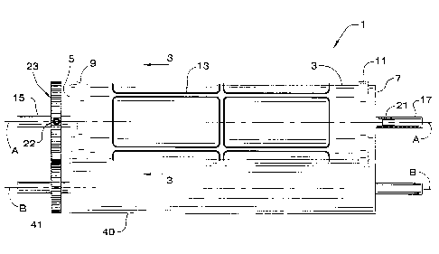
Fig. 1 is a front elevation of a rotary cutting
die of the present invention in combination with an anvil
roll;
Fig. 2 is a partially separated perspective of
the rotary cutting die in combination with the anvil
roll; and
Fig. 3 is a section taken along line 3-3 of
Fig. 1 showing cutting blades and thick chrome plating on
the die of the present invention.
Corresponding reference characters indicate
corresponding parts throughout the several views of the
drawings.
Detailed Description of the Preferred Embodiment
Referring now to the drawings, and in
particular to Figures 1 and 2, a rotary cutting die of
the present invention for cutting sections from sheet
material is generally referred to by the reference
numeral 1. The die 1 comprises a generally cylindrical
body 3 extending along a central axis A between a first
end 5 and a second end 7. The body 3 has a substantially
constant diameter along its entire length excluding
circular bearing surfaces or lands 9, 11 positioned
adjacent the ends 5, 7 of the body. At least one cutting
blade 13 extends outward from the surface of the body to
a tip. Opposite journal shafts 15, 17 extend axially
from the first and second ends 5, 7, respectively, of the
body 3. The tip of each cutting blade 13 traces an
outline of the shape which is desired to be cut from the
material. The number of cutting blades used depends on
the number of sections desired. Although a plurality of
cutting blades are described with respect to the
disclosed embodiment, it will be understood that the
rotary cutting die may have only one cutting blade
without departing from the scope of the present
CA 02358370 2001-10-09
invention. The journal shafts 15, 17 are coaxial with
the body 3 and have a diameter generally equal to one
another and substantially constant. The body 3 is of a
larger diameter than the journal shafts 15, 17.
5 The journal shafts 15, 17 include flats 19, 21,
respectively, which cooperate with a set screw 22 to
fasten a mating gear 23 to the rotary cutting die 1. The
mating gear 23 has a central hole 27 sized for receiving
the corresponding journal shaft 15, 17 so it abuts the
corresponding end 5, 7 of the body 3. Once the mating
gear 23 is in place, the set screw 22 is tightened
against the corresponding flat 19, 21 to hold the mating
gear and the rotary cutting die 1 in driving engagement
to ensure they rotate together without slipping. It is
envisioned that other means of holding the gear on the
shaft (e. g., bolt circles) may be used without departing
from the~scope of the present invention. '
The journal shafts 15, 17 enable the rotary
cutting die 1 to be rotatably mounted on a conventional
cutting die press (not shown) and are sized and shaped
suitably therefor. A drive gear (not shown) of the
conventional cutting die press meshes with the mating
gear 23 to rotate the rotary cutting die 1. A
conventional anvil roll 40, shown in Figures 1 and 2, is
mounted on the conventional cutting die press parallel to
the rotary cutting die 1 and includes an anvil roll gear
41 that meshes with the mating gear 23 causing the anvil
roll and rotary cutting die 1 to rotate simultaneously in
opposite directions. Alternatively, the anvil roll gear
41 may mesh with the drive gear of the conventional
cutting die press to rotate the anvil roll 40 and
therefore the rotary cutting die 1.
The bearing surfaces 9, 11 are circular and
have a larger diameter than the body 3. The diameter of
the bearing surfaces 9, 11 is equal to or slightly
greater than the diameter of the tips of the cutting
CA 02358370 2001-10-09
6
blades 13. For example, in one embodiment, the body 3
has a diameter of about 3 inches, the bearing surfaces 9,
11 have diameters of about 3.060 inches and the cutting
blades 13 have a diameter of about 3.054 inches. The
bearing surfaces 9, 11 engage the anvil roll 40 and
ensure a constant distance between the anvil roll axis B
and the axis of the body 3 thereby controlling the
distance between the anvil roll 40 and the tips of the
cutting blades 13.
In operation, a continuous sheet or web of
material, such paper, cardboard, plastic or foil, passes
between the rotary cutting die 1 and the anvil roll 40 as
they rotate and the cutting blades 13 cut sections of
material from the web. Frequently, the cutting blades 13
cut sections completely out of the material. However, in
certain operations such as the manufacture of labels, the
cutting,blades may cut only partially through the
material.
The rotary cutting die 1 is formed from a piece
of round bar stock of steel such as AISI 4150 medium
carbon steel having a Rockwell C scale hardness of about
20.5. A conventional machine tool, such as a lathe, is
used to machine the bearing surfaces 9, 11, the journal
shafts 15, 17, and the first and second ends 5, 7 of the
body 3. Next, the flats 19, 21 are machined into the
journal shafts 15, 17 using a suitable cutting tool such
as an end mill.
After initial machining of the rotary cutting
die 1 is complete, the journal shafts 15, 17 and the
bearing surfaces 9, 11 are hardened by heating them to an
elevated temperature, typically about 1000'F to 1400'F,
and then quenching them. Preferably, the bearing
surfaces 9, 11 and the journal shafts 15, 17 are heat
treated using a conventional induction heating method
wherein the rotary cutting die 1 is placed inside a wound
coil subjected to alternating current. The changing
CA 02358370 2001-10-09
7
magnetic field produced by current passing through the
coil induces an electrical current in selected portions
of the rotary cutting die (e.g., the journal shafts 9, 11
and the bearing surfaces 15, 17). The current heats the
surface layers of the die by electrical resistance. As
will be appreciated by those skilled in the art, the rate
and the depth of the heat treatment can be controlled by
the amperage and frequency of the electrical current
passed through the coil. This method of heating is very
efficient and heating rates are extremely rapid. Thus,
the cost and operation time are relatively low. Further,
it is envisioned that this heat treatment method can be
automated for greater accuracy and to provide highly
reproducible results. Induction heating is also
advantageous because it produces very little distortion
due to the rigidity of the cool interior of the body 3
and because it facilitates hardening selected surface
areas without affecting other surfaces areas (e.g., the
body 3). As will be understood by those skilled in the
art, other suitable selective heat treatment techniques
may be employed, such as flame hardening, electron beam
hardening or the use of a laser beam having a beam size,
intensity and scanning speed sufficient to produce
adequate hardness.
After heating, the journal shafts 9, 11 and the
bearing surfaces 15, 17 are preferably quenched by
submersing them in a suitable quenching liquid. However,
other methods of quenching may be used if desired. This
hardening process provides the bearing surfaces 9, 11 and
the journal shafts 15, 17 with a Rockwell C scale
hardness greater than about 50 without hardening the body
3 of the rotary cutting die 1 thereby maintaining the
body at a Rockwell C scale hardness less than about 50.
Preferably, the bearing surfaces 9, 11 and the journal
shafts 15, 17 are heat treated to a Rockwell C scale
hardness greater than 54, and more preferably between
CA 02358370 2001-10-09
8
about 57 and 59, and the body 3 is maintained at a
Rockwell C scale hardness less than about 21.
After heat treatment is complete, the bearing
surfaces 9, 11 and the journal shafts 15, 17, including
the flats 19, 21, are ground to their finished
dimensions. Preferably, grinding is performed on a
cylindrical external-grinding machine for maximum
accuracy. However, it will be understood that any
suitable grinding process producing finished surfaces of
the required dimensions and tolerances may be employed.
For example, the process may include use of a tool-post
grinder on a conventional lathe, grinding by hand on a
pedestal or bench grinder, or the use of grinding wheels
mounted on portable, high speed electric or air motors.
Also following heat treatment, the cutting
blades 13 are machined to the desired shape from the body
3 of the. rotary cutting die 1 using a suitable cutting
tool. This process produces the cutting blades 13 in
their finished shape and dimensions. Because the cutting
blades 13 are not heat treated, they are not subjected to
distortion and therefore no sharpening is required.
Preferably, the cutting blades 13 are machined with an
end mill or frusto conical milling cutter using a
computerized numerical control (CNC) machining center
with multiple axes. However, it will be understood that
any suitable machine tool or machining process may be
employed, such as column and knee, turret, or bed type
milling machines. Alternatively, it will be understood
that the cutting blades 13 may be machined prior to
grinding the bearing surfaces 9, 11 and the journal
shafts 15, 17. Further, it will also be understood that
the cutting blades 13 may be machined prior to heat
treatment of the bearing surfaces 9, 11 and the journal
shafts 15, 17 without departing from the scope of the
present invention.
Finally, the entire rotary cutting die 1 is
CA 02358370 2001-10-09
9
chrome plated to enhance the wear resistance of the
unhardened cutting blades 13. Preferably, the die is .
subjected to the chrome plating for an extended period of
time (e. g., about 20 minutes) compared to previous
conventional methods of manufacturing rotary cutting
dies. This provides chrome plating with a maximum
thickness greater than about 0.0004 inches, and more
preferably greater than about 0.0007 inches. As shown in
Fig. 3, the maximum thickness of the chrome plating
occurs at the tips of the cutting blades 13. Preferably,
this thickness is about 0.001 inches to provide the
blades with sufficient hardness. Although the plating
may have other hardnesses without departing from the
scope of the present invention, in one embodiment the
plating has a hardness of between about 1000 and about
1150 measured on a KHN100 microhardness scale. Further,
although. chrome plating is used in one embodiment, other
hardfacing techniques such as TIN, TICN and TIALN may be
used without departing from the scope of the present
invention.
Dies 1 of the present invention have a blade
height H of about 0.020 inches to about 0.040 inches and
more preferably about 0.030 inches after plating as
compared to conventional blades which have a height of
about 0.050 inches. As will be appreciated by those
skilled in the art, shorter blades provide more evenly
distributed plating and sharper finished blade tips
because of the enhanced electromagnetic properties
associated with the shorter blades.
It will be apparent from the foregoing that the
method of manufacturing a rotary cutting die described
above has many advantages. First, by heat treating only
the bearing surfaces 9, 11 and the journal shafts 15, 17,
the present method produces a rotary cutting die having
bearing surfaces and journal shafts with a Rockwell C
scale hardness greater than about 50 and a body with a
CA 02358370 2001-10-09
1~
Rockwell C scale hardness less than about 50. Because
the body 3 is not hardened, the cutting blades 13 can be
machined from the body after heat treatment of the
bearing surfaces 9, 11 and the journal shafts 15, 17, if
desired. Furthermore, because the body 3 and the cutting
blades 13 are not subjected to heat treatment, they do
not distort after initial machining. Thus, the cutting
blades 13 can be machined in a single operation and do
not require extra sharpening to bring them to their
finished dimensions. This reduces the cost and time
required to manufacture the rotary cutting die 1. Also,
by providing thick chrome plating on the surface of the
rotary cutting die 1, the present method gives the
cutting blades 13 sufficient hardness so they do not
exhibit significant wear despite being heat treated.
This thick chrome plating thereby gives the cutting
blades a~.longer useful life with respect to prior methods
of manufacturing rotary cutting dies (e.g., about 5
million cutting revolutions as compared to about 2
million cutting revolutions). Finally, because only the
bearing surfaces 9, 11 and the journal shafts 15, 17 are
heat treated, the rotary cutting die can be manufactured
from steel which is not heat treated before initial
machining and therefore is relatively inexpensive and
easily machinable.
In view of the above, it will be seen that the
several objects of the invention are achieved and other
advantageous results attained.
Although the method of the present invention
applies to the manufacturing of rotary cutting dies as
herein described, the method is not limited to such
rotary cutting dies and may be applied to the manufacture
of any rotary cutting die having a generally cylindrical
body with at least one bearing surface thereon.
When introducing elements of the present
invention or the preferred embodiments) thereof, the
CA 02358370 2001-10-09
11
articles "a", "an", "the" and "said" are intended to mean
that there are one or more of the elements. The terms
"comprising", "including" and "having" are intended to be
inclusive and mean that there may be additional elements
other than the listed elements.
As various changes could be made in the above
constructions without departing from the scope of the
invention, it is intended that all matter contained in
the above description or shown in the accompanying
drawings shall be interpreted as illustrative and not in
a limiting sense.