Sélection de la langue

Search

Sommaire du brevet 2359973 

Énoncé de désistement de responsabilité concernant l'information provenant de tiers

Une partie des informations de ce site Web a été fournie par des sources externes. Le gouvernement du Canada n'assume aucune responsabilité concernant la précision, l'actualité ou la fiabilité des informations fournies par les sources externes. Les utilisateurs qui désirent employer cette information devraient consulter directement la source des informations. Le contenu fourni par les sources externes n'est pas assujetti aux exigences sur les langues officielles, la protection des renseignements personnels et l'accessibilité.

Disponibilité de l'Abrégé et des Revendications

L'apparition de différences dans le texte et l'image des Revendications et de l'Abrégé dépend du moment auquel le document est publié. Les textes des Revendications et de l'Abrégé sont affichés :

  • lorsque la demande peut être examinée par le public;
  • lorsque le brevet est émis (délivrance).
(12) Brevet: (11) CA 2359973
(54) Titre français: POMPE DE PROPULSION A EJECTEUR
(54) Titre anglais: JET PROPULSION PUMP
Statut: Périmé et au-delà du délai pour l’annulation
Données bibliographiques
(51) Classification internationale des brevets (CIB):
  • B63H 11/08 (2006.01)
  • B63H 11/04 (2006.01)
(72) Inventeurs :
  • ZWAAN, HENDRIK JOHANNES (Australie)
  • ZWAAN, CRAIG (Australie)
(73) Titulaires :
  • HENDRIK JOHANNES ZWAAN
  • CRAIG ZWAAN
(71) Demandeurs :
  • HENDRIK JOHANNES ZWAAN (Australie)
  • CRAIG ZWAAN (Australie)
(74) Agent: NORTON ROSE FULBRIGHT CANADA LLP/S.E.N.C.R.L., S.R.L.
(74) Co-agent:
(45) Délivré: 2008-03-11
(86) Date de dépôt PCT: 1999-12-22
(87) Mise à la disponibilité du public: 2000-07-13
Requête d'examen: 2004-12-07
Licence disponible: S.O.
Cédé au domaine public: S.O.
(25) Langue des documents déposés: Anglais

Traité de coopération en matière de brevets (PCT): Oui
(86) Numéro de la demande PCT: PCT/AU1999/001136
(87) Numéro de publication internationale PCT: WO 2000040461
(85) Entrée nationale: 2001-07-06

(30) Données de priorité de la demande:
Numéro de la demande Pays / territoire Date
PP 8047 (Australie) 1999-01-07

Abrégés

Abrégé français

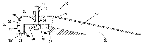
Cette invention se rapporte à une pompe de propulsion à éjecteur (10) pour engin aquatique, qui comprend une hélice (40) montée sur un arbre (42) en vue d'effectuer un mouvement de rotation axial, et une chambre de pompe (20) comportant une entrée cylindrique (30) et une sortie à inclinaison descendante (50) reliée à une ouverture (29) ménagée dans la chambre de pompe (20). L'hélice (40) est placée à l'intérieur de l'entrée cylindrique (30). Une partie paroi extérieure (24) de la chambre (20) de la pompe est spiralée vers l'extérieur depuis l'entrée cylindrique (30) afin d'aider l'écoulement de fluide à entrer dans la chambre (20) de la pompe par l'entrée cylindrique (30) et à être expulsé de la chambre (20) de la pompe par la sortie à inclinaison descendante (50).


Abrégé anglais


A jet propulsion pump (10) for use with watercraft includes a propeller (40)
mounted on a shaft (42) for axial rotation, and a pump
chamber (20) having a cylindrical inlet (30) and a downwardly inclined outlet
(50) connected to an aperture (29) in the pump chamber (20).
The propeller (40) is positioned within the cylindrical inlet (30). An outer
wall portion (24) of the pump chamber (20) is outwardly spiralling
from the cylindrical inlet (30) to assist flow of fluid entering the pump
chamber (20) through the cylindrical inlet (30) and expelling from
the pump chamber (20) at the downwardly inclined outlet (50).

Revendications

Note : Les revendications sont présentées dans la langue officielle dans laquelle elles ont été soumises.


7
CLAIMS:
1. A jet propulsion pump having a pump chamber, a shaft, a propeller mounted
on the
shaft for axial rotation, means to support the shaft for axial rotation with
the propeller
positioned within the pump chamber, an aperture in the pump chamber, and a
downwardly inclined outlet connected to the aperture in the pump chamber,
wherein the
pump chamber comprises a cylindrical inlet located within the pump chamber and
the
propeller being mounted in the cylindrical inlet, an inner circumferential
wall, an
outwardly spiralling outer wall portion having an upper edge, the inner
circumferential
wall defining a space integral with the cylindrical inlet, the pump chamber
further having
a base wall, the inner circumferential wall and the outwardly spiralling outer
wall portion
having respective lower edges which are substantially horizontally aligned
with one
another and which are interconnected by the base wall, and an upper wall
integral with
the upper edge of the outwardly spiralling outer wall portion, the arrangement
being such
that, in use, fluid is lifted by the propeller into the pump chamber through
the cylindrical
inlet and then caused to flow radially along the upper wall and conjoining
surfaces to pass
through the aperture into the outlet.
2. A jet propulsion pump according to claim 1, wherein the downwardly inclined
outlet is
disposed at an acute angle below a horizontal plane.
3. A jet propulsion pump according to claim 2, wherein the acute angle is from
between
12 degrees and 16 degrees.
4. The jet propulsion pump according to claim 1, wherein the downwardly
inclined outlet
has a substantially smaller transverse cross-sectional area than a lateral
cross-sectional
area of the cylindrical inlet.
5. The jet propulsion pump according to claim 4, wherein the cross-sectional
area of the
downwardly inclined outlet is from between 15 to 40% of the lateral cross-
sectional area
of the cylindrical inlet.

8
6. A jet propulsion pump according to claim 4, wherein the transverse cross-
sectional area
of the downwardly inclined outlet is about 20% of the lateral cross-sectional
area of the
cylindrical inlet.
7. A jet propulsion pump according to claim 1, wherein the upper edges of the
propeller
are horizontally aligned with an upper edge of the cylindrical inlet.
8. A jet propulsion pump according to claim 1, wherein the lower edges of the
propeller
are spaced apart from and above a lower edge of the cylindrical inlet.
9. A jet propulsion pump according to claim 8, wherein the lower edges of the
propeller
are disposed at least 13 mm above the lower edge of the cylindrical inlet.
10. The jet propulsion pump according to claim 9, wherein a distance between
the
outwardly spiralling wall portion and the inner circumferential wall
incrementally
increases from zero at a first end of the outwardly spiralling wall portion to
a maximum
distance at a second end of the outwardly spiralling wall portion, wherein the
second end
is adjacent to the downwardly inclined outlet.
11. The jet propulsion pump according to claim 10, wherein a cross-sectional
area of the
pump chamber disposed between the inner circumferential wall and the outwardly
spiralling wall portion increases to up to 40% of the lateral cross-sectional
area of the
cylindrical inlet.
12. A jet propulsion pump according to claim 11, wherein a cross-sectional
area of the
pump chamber disposed between the inner circumferential wall and the outwardly
spiraling wall portion increases to up to 25% of the lateral cross-sectional
area of the
cylindrical inlet.
13. A jet propulsion pump according to claim 1, wherein a height difference
between the
outwardly spiraling outer wall and the inner circumferential wall is 30 to 40%
of a radius
of the cylindrical inlet.
14. A jet propulsion pump according to claim 1, wherein an upper wall of the
pump
chamber is provided with a downwardly depending substantially conical member
with a

9
curved wall, wherein the conical member radially extends from an aperture for
receiving
the shaft in the horizontal upper wall.
15. A watercraft including a jet propulsion pump according to claim 1, wherein
the jet
propulsion pump is mounted in a floor of the watercraft, intermediate fore and
aft of the
watercraft.
16. A watercraft according to claim 15, characterised in that the jet
propulsion pump is
mounted in a substantially central position in the floor of the watercraft.
17. A watercraft according to claim 15, wherein the jet propulsion pump is
enclosed in a
pump housing, the pump housing being slidably received within a receiving
means
integral with the floor of the watercraft.

Description

Note : Les descriptions sont présentées dans la langue officielle dans laquelle elles ont été soumises.


CA 02359973 2007-02-23
1
TITLE
"JET PROPULSION PUMP"
FIELD OF THE INVENTION
This invention relates to a jet propulsion pump and in particular relates to a
jet propulsion
pump for use in canoes, kayaks and similar watercraft.
SUMMARY OF THE INVENTION
In accordance with a first aspect of the present invention there is provided a
jet propulsion
pump including a propeller mounted on a shaft for axial rotation, means to
axially support
the shaft with the propeller positioned within a pump chamber, and a
downwardly
inclined outlet connected to an aperture in the pump chamber. In accordance
with a
second aspect of the present invention there is provided a watercraft
including a jet
propulsion pump mounted in a floor of the watercraft, intermediate fore and
aft of the
watercraft, wherein the jet propulsion pump is in accordance with the present
invention.
In accordance with another aspect of the present invention, there is provided
a jet
propulsion pump having a pump chamber, a shaft, a propeller mounted on the
shaft for
axial rotation, means to support the shaft for axial rotation with the
propeller positioned
within the pump chamber, an aperture in the pump chamber, and a downwardly
inclined
outlet connected to the aperture in the pump chamber, wherein the pump chamber
comprises a cylindrical inlet located within the pump chamber and the
propeller being
mounted in the cylindrical inlet, an inner circumferential wall, an outwardly
spiralling
outer wall portion having an upper edge, the inner circumferential wall
defining a space
integral with the cylindrical inlet, the pump chamber further having a base
wall, the inner
circumferential wall and the outwardly spiralling outer wall portion having
respective
lower edges which are substantially horizontally aligned with one another and
which are
interconnected by the base wall, and an upper wall integral with the upper
edge of the
outwardly spiralling outer wall portion, the arrangement being such that, in
use, fluid is
lifted by the propeller into the pump chamber through the cylindrical inlet
and then

CA 02359973 2007-02-23
la
caused to flow radially along the upper wall and conjoining surfaces to pass
through the
aperture into the outlet.
DESCRIPTION OF THE DRAWINGS
The present invention will now be described, by way of example only, with
reference to
the accompanying drawings, in which:-
Figure 1 is an upper perspective view of a jet propulsion pump in accordance
with the
present invention;
Figure 2 is a lower perspective view of a jet propulsion pump in accordance
with the
present invention;
Figure 3 is a longitudinal cross-sectional view of the jet propulsion pump in
accordance
with the present invention;
Figure 4 is a transverse cross-sectional view of the jet propulsion pump in
accordance
with the present invention;

CA 02359973 2001-07-06
WO 00/40461 PCT/AU99/01136
2
Figure 5 is a lateral cross-sectional view of the jet propulsion pump in
accordance
with the present invention; and
Figure 6 is a side plan view of the jet propulsion pump as arranged to be used
in a
boat in conjunction with a driving motor, in accordance with the present
invention;
DETAILED DESCRIPTION OF AN EMBODIMENT OF THE INVENTION
Referring to Figures 1 to 5 there is shown a jet propulsion pump 10 having a
pump
chamber 20, a cylindrical inlet 30, a propeller 40 and an outlet 50.
As shown in Figures 3, 4 and 5, the pump chamber 20 includes an inner
circumferential wall 22 and an outwardly spiraling outer wall portion 24. A
first end
25 of the outwardly spiralling wall portion 24 is contiguous with and
outwardly
spiraling from an outer surface 23 of the inner circumferential wall 22. A
second end
of the outwardly spiralling outer wall portion 24 is integral with a first end
of a
hollow elbow portion 27 disposed adjacent the first end 25 of the outwardly
spiraling
outer wall portion 24. A second end of the hollow elbow portion 27 is integral
with
the outlet 50. The hollow elbow portion 27 provides an outlet aperture 29 in
the
pump chamber 20 from which fluid taken into the pump chamber 20 may be
expelled.
As shown in Figures 3 and 4, the outwardly spiraling outer wall portion 24 is
of
greater height than the inner circumferential wall 22. Preferably the
difference in
height between the outwardly spiraling outer wall portion 24 and the inner
circumferential wall 22 is 30-45% of the radius of the cylindrical inlet 30,
with
optimal pump performance achieved when the difference in height between the
outwardly spiraling outer wall portion 24 and the inner circumferential inner
wall 22
is 37.5% of the radius of the cylindrical inlet 30.

CA 02359973 2001-07-06
WO 00/40461 PCT/AU99/01136
3
Lower edges of the inner circumferential wall 22 and the outwardly spiraling
outer
wall portion 24 are substantially horizontally aligned and interconnected by a
horizontal base wall 26. A substantially horizontal upper wall 28 is integral
with an
upper edge of the curved outer wall portion 24.
As shown in Figure 5, an inner surface 32 of the outwardly spiraling outer
wall
portion 24 is spaced apart from the outer surface 23 of the inner
circumferential wall
22 such that the distance between the inner surface 32 of the outwardly
spiraling
outer wall portion 24 and the outer surface 23 of the inner circumferential
wall 22
incrementally increases from zero, where an edge of the outwardly spiraling
outer
wall portion 24 is contiguous with an outer surface 23 of the inner
circumferential
wall 22, to a maximum distance adjacent the first end of the elbow portion 27.
Preferably, the distance between the inner surface 32 of the outwardly
spiraling outer
wall portion 24 and the outer surface 23 of the inner circumferential wall 22
incrementally increases from zero to a distance where a cross-sectional area
of the
pump chamber 20 disposed between the inner circumferential wall and the
outwardly
spiraling outer wall portion 24 is up to 40% of the cross-sectional area of
the
cylindrical inlet 30. Optimal pump performance may be achieved when the cross-
sectional area of the pump chamber 20 disposed between the inner
circumferential
wall 22 and the outwardly spiraling outer wall portion 24 adjacent the elbow
27 is
about 25% of the cross-sectional area of the cylindrical inlet 30.
The cylindrical inlet 30 of the jet propulsion pump 10 includes a space
integral with
the inner surface 34 of the inner circumferential wall 22.
As shown in Figures 3 and 4, the horizontal upper wall 28 is provided with a
downwardly depending substantially curved conical member 46 which radially
extends from a first aperture 44 in the horizontal upper wall 28. The first
aperture 44

CA 02359973 2001-07-06
WO 00/40461 PCT/AU99/01136
4
is arranged to receive a shaft 42 on which the propeller 40 is mounted for
axial
rotation. The propeller 40 is disposed such that the rotational path of the
propeller 40
is in close proximity to an inner surface 34 of the inner circumferential wall
22.
Preferably, in order to provide optimal efficiency of the jet propulsion pump
10,
upper edges of the propeller 40 are horizontally aligned with upper edges of
the inner
circumferential wall 22. Furthermore, in order to provide optimal efficiency
of the
jet propulsion pump 10, lower edges of the propeller 40 should preferably be
aligned
at least 13mm above lower edges of the inner circumferential wall 22.
The outlet 50 includes a hollow tube member 52 endwise connected to the second
end of the elbow portion 27. The cross-sectional area of the hollow tube
member 52
is between 15-40% respectively, of the cross-sectional area of the cylindrical
inlet
30. Preferably, the cross-sectional area of the hollow tube member 52 is 20%
of the
cross-sectional area of the cylindrical inlet 30.
The hollow tube member 52 is arranged to downwardly incline at an acute angle
from the horizontal, preferably from between 12 to 16 from the horizontal.
In the present invention, as shown in Figure 6, there is provided a watercraft
100
where the jet propulsion pump 10 is mounted intermediate fore and aft of the
watercraft such that the outlet is directed towards the rear of the
watercraft. Fluid
flow is expelled from the downwardly inclined outlet 50 directly into a water
body.
Preferably, the jet propulsion pump 10 is mounted in a substantially central
position
in a base of a watercraft. It has been found that a central positioning of the
jet
propulsion pump 10 in the watercraft has the effect of trimming the nose of
the
watercraft, as well as assisting steerage of the watercraft. ----w
It is envisaged that the jet propulsion pump 10 may be provided with a pump
housing, the pump housing being slidably received in a receiving means which
is

CA 02359973 2001-07-06
WO 00/40461 PCT/AU99/01136
integral with the base of the watercraft 100. The pump housing includes a base
portion which is integral with the jet propulsion pump 10, a portion
accommodating
an inwardly extending flange at its lower edge and an outwardly extending
flange at
its upper edge, and a lid portion. The pump housing is assembled by fixedly
5 attaching, by conventional fixing means, the mating faces of the inwardly
extending
flange of the wall portion and the base portion. The lid portion rests on top
of the
outwardly extending flange of the wall portion and may be secured thereto with
a
plurality of clips. The lid portion is provided with a plurality of apertures
arranged to
receive a control console, or fuel cap associated with the motor fitted to the
jet
propulsion pump 10. The lid portion also accommodates a handle for
conveniently
carrying the pump housing.
In this way, the jet propulsion pump 10 and pump housing may be conveniently
removed from the watercraft 100 for repairs or maintenance.
In use, the jet propulsion pump 10 is arranged to be mounted in a base of the
watercraft, at any position intermediate fore and aft of the watercraft. In
this way, a
lower portion of the pump, including the cylindrical inlet 30 and the outlet
50 will be
immersed below the waterline.
A drive motor is mounted above the jet propulsion pump 10 and is arranged to
axially rotate the shaft 42 and thereby drive the propeller 40. In use, the
propeller 40
is arranged to draw fluid into the cylindrical inlet 30 and direct fluid flow
into the
pump chamber 20. The downwardly depending substantially curved conical member
46 is arranged to provide a streainlined path for the fluid flow into the pump
chamber
20 as fluid is drawn into the cylindrical inlet 30, thereby assisting the
efficiency-of
the jet propulsion pump 10.

CA 02359973 2001-07-06
WO 00/40461 PCT/AU99/01136
6
The outwardly spiraling outer wall portion 24 of the pump chamber 20 is
arranged to
direct and streamline fluid flow from the pump chamber 20 to the outlet 50.
The
outlet 50 has a substantially narrower cross-sectional area than the
cylindrical inlet
30. Fluid flow is therefore much faster at the outlet 50 than fluid flow at
the
cylindrical inlet 30, which accounts for the jet propulsion action of the
present
invention. Furthermore, the outlet 50 is arranged to direct fluid flow out of
the pump
chamber at an acute angle below the horizontal 20 which has the effect of
trimming
the nose of the watercraft.
Modifications and variations such as would be apparent to a skilled addressee
are
deemed to be within the scope of the present invention.

Dessin représentatif
Une figure unique qui représente un dessin illustrant l'invention.
États administratifs

2024-08-01 : Dans le cadre de la transition vers les Brevets de nouvelle génération (BNG), la base de données sur les brevets canadiens (BDBC) contient désormais un Historique d'événement plus détaillé, qui reproduit le Journal des événements de notre nouvelle solution interne.

Veuillez noter que les événements débutant par « Inactive : » se réfèrent à des événements qui ne sont plus utilisés dans notre nouvelle solution interne.

Pour une meilleure compréhension de l'état de la demande ou brevet qui figure sur cette page, la rubrique Mise en garde , et les descriptions de Brevet , Historique d'événement , Taxes périodiques et Historique des paiements devraient être consultées.

Historique d'événement

Description Date
Le délai pour l'annulation est expiré 2010-12-22
Lettre envoyée 2009-12-22
Déclaration du statut de petite entité jugée conforme 2008-12-22
Accordé par délivrance 2008-03-11
Inactive : Page couverture publiée 2008-03-10
Inactive : Lettre officielle 2007-10-15
Préoctroi 2007-10-05
Inactive : Taxe finale reçue 2007-10-05
Un avis d'acceptation est envoyé 2007-05-24
Lettre envoyée 2007-05-24
Un avis d'acceptation est envoyé 2007-05-24
Inactive : Grandeur de l'entité changée 2007-05-09
Inactive : Approuvée aux fins d'acceptation (AFA) 2007-04-30
Modification reçue - modification volontaire 2007-02-23
Inactive : Correspondance - Formalités 2007-01-31
Inactive : Dem. de l'examinateur par.30(2) Règles 2006-08-24
Lettre envoyée 2004-12-23
Exigences pour une requête d'examen - jugée conforme 2004-12-07
Modification reçue - modification volontaire 2004-12-07
Toutes les exigences pour l'examen - jugée conforme 2004-12-07
Requête d'examen reçue 2004-12-07
Inactive : Grandeur de l'entité changée 2004-01-15
Inactive : Lettre officielle 2002-04-23
Inactive : Inventeur supprimé 2002-04-22
Inactive : Notice - Entrée phase nat. - Pas de RE 2002-04-22
Inactive : Demandeur supprimé 2002-04-22
Inactive : Correspondance - Formalités 2001-12-05
Inactive : Page couverture publiée 2001-11-22
Inactive : Inventeur supprimé 2001-11-15
Inactive : Notice - Entrée phase nat. - Pas de RE 2001-11-15
Inactive : CIB en 1re position 2001-11-15
Demande reçue - PCT 2001-11-07
Demande publiée (accessible au public) 2000-07-13
Déclaration du statut de petite entité jugée conforme 1999-12-22

Historique d'abandonnement

Il n'y a pas d'historique d'abandonnement

Taxes périodiques

Le dernier paiement a été reçu le 2007-12-11

Avis : Si le paiement en totalité n'a pas été reçu au plus tard à la date indiquée, une taxe supplémentaire peut être imposée, soit une des taxes suivantes :

  • taxe de rétablissement ;
  • taxe pour paiement en souffrance ; ou
  • taxe additionnelle pour le renversement d'une péremption réputée.

Veuillez vous référer à la page web des taxes sur les brevets de l'OPIC pour voir tous les montants actuels des taxes.

Historique des taxes

Type de taxes Anniversaire Échéance Date payée
TM (demande, 2e anniv.) - petite 02 2001-12-24 2001-07-06
Taxe nationale de base - petite 2001-07-06
TM (demande, 3e anniv.) - petite 03 2002-12-23 2002-11-14
TM (demande, 4e anniv.) - générale 04 2003-12-22 2003-12-17
TM (demande, 5e anniv.) - générale 05 2004-12-22 2004-12-06
Requête d'examen - générale 2004-12-07
TM (demande, 6e anniv.) - générale 06 2005-12-22 2005-12-07
TM (demande, 7e anniv.) - générale 07 2006-12-22 2006-11-29
Taxe finale - petite 2007-10-05
TM (demande, 8e anniv.) - petite 08 2007-12-24 2007-12-11
TM (brevet, 9e anniv.) - petite 2008-12-22 2008-12-22
Titulaires au dossier

Les titulaires actuels et antérieures au dossier sont affichés en ordre alphabétique.

Titulaires actuels au dossier
HENDRIK JOHANNES ZWAAN
CRAIG ZWAAN
Titulaires antérieures au dossier
S.O.
Les propriétaires antérieurs qui ne figurent pas dans la liste des « Propriétaires au dossier » apparaîtront dans d'autres documents au dossier.
Documents

Pour visionner les fichiers sélectionnés, entrer le code reCAPTCHA :


Pour visualiser une image, cliquer sur un lien dans la colonne description du document. Pour télécharger l'image (les images), cliquer l'une ou plusieurs cases à cocher dans la première colonne et ensuite cliquer sur le bouton "Télécharger sélection en format PDF (archive Zip)" ou le bouton "Télécharger sélection (en un fichier PDF fusionné)".

Liste des documents de brevet publiés et non publiés sur la BDBC .

Si vous avez des difficultés à accéder au contenu, veuillez communiquer avec le Centre de services à la clientèle au 1-866-997-1936, ou envoyer un courriel au Centre de service à la clientèle de l'OPIC.


Description du
Document 
Date
(aaaa-mm-jj) 
Nombre de pages   Taille de l'image (Ko) 
Dessin représentatif 2001-11-21 1 8
Revendications 2001-07-06 4 128
Abrégé 2001-07-06 1 49
Dessins 2001-07-06 4 54
Description 2001-07-06 6 221
Page couverture 2001-11-22 1 38
Revendications 2007-02-23 3 103
Description 2007-02-23 7 251
Dessin représentatif 2008-02-08 1 8
Page couverture 2008-02-08 1 39
Avis d'entree dans la phase nationale 2001-11-15 1 195
Avis d'entree dans la phase nationale 2002-04-22 1 194
Rappel - requête d'examen 2004-08-24 1 117
Accusé de réception de la requête d'examen 2004-12-23 1 176
Avis du commissaire - Demande jugée acceptable 2007-05-24 1 165
Avis concernant la taxe de maintien 2010-02-02 1 171
PCT 2001-07-06 11 426
Correspondance 2001-12-05 1 25
Correspondance 2002-04-22 1 12
Correspondance 2007-01-31 2 62
Correspondance 2007-07-31 1 40
Correspondance 2007-10-15 2 47
Correspondance 2007-10-05 3 98
Correspondance 2008-12-22 1 36