Note : Les descriptions sont présentées dans la langue officielle dans laquelle elles ont été soumises.
CA 02360161 2007-03-26
-1-
BALL TRACK
The present invention relates to a ball track composed of individual
components with running
tracks that have a guide for rolling balls, and with connecting elements that
have a ball
passageway substantially vertical and/or distinctly inclined with respect to
the horizontal,
wherein the running tracks are provided with at least one through aperture or
respectively
through bore for transferring a ball to another component.
Numerous configurations of ball tracks are known, and commercially available.
The great
majority of the ball tracks concerned have running tracks that are fixed, and
mostly installed
one above another. These ball tracks, mostly made in one piece, have the
advantage that they
can be played with immediately. Because of the fixed, pre-determined paths and
as use of the
track is limited to using a ball or another suitable object, the ball track
user quickly loses
interest in it.
The ball track known from German utility model patent GM 75 11 147, published
on
November 20, 1975, that forms the prior art on which the present invention is
based, has the
advantage that the user is given a certain degree of freedom in the layout of
the ball track.
This ensures that the user's interest in the ball track, in particular the
interest of a playing
child, is maintained for a greater period of time. The pedagogical value of
such variable
tracks is far greater, as the imagination and the child's logical and
constructive thinking is
more strongly promoted in this case.
With this known ball track, the running tracks are inclined in order to
accelerate the balls
along said running tracks, so the running tracks can only be played with from
one direction.
Further, this ball track has the disadvantage that no provision is made for
assembling several
running tracks one above another. Because the tracks are inclined, there is no
simple way of
building up the connecting elements on top of one another, so when assembled
together, in
particular in the case of tall constructions, the ball track is unstable.
A ball track with parallel tracks is known from utility model patent
application
DE 296 15 318. With this fixed construction ball track, the balls go through a
bore in the
running tracks onto a circular track segment. In this way the balls
accelerated by free fall are
steered onto the horizontal running tracks below. Because of the single piece
configuration,
however, no flexibility is possible
CA 02360161 2001-07-19
-2-
with respect to the layout.
A variable ball track is also known from GB 2285755. However, in this case
running tracks and
connecting elements are prefabricated in a single piece. In addition, the
running tracks of the as-
sembled components are inclined, so the rolling element components can only
travel in a direction
pre-determined in the manufacturing process.
The toy building set of DE 25 47 070 is constructed in a comparable manner. In
this case, rectangu-
lar building blocks with an inclined groove and a gap at the lowest point are
arranged on top of one
another. In this case also, the direction of travel of the ball is pre-
determined because of the pre-
fabricated building blocks.
In DE 24 42 904 an attempt is made to increase the variability of the ball
track by making running
tracks that can be placed or hooked into hollow cylindrical connecting
elements. This construction
is always unstable, however. In addition, because of the inclined arrangement
of the running tracks,
reversing the direction of travel on a running track is not possible.
Lastly, German utility patent DE 1 676 519 discloses a variable ball track.
Variability is limited,
however, to tracks arranged in an inclined manner being placed in connecting
elements that are ar-
ranged on pillars of different heights, wherein the connecting elements can be
rotated about a verti-
cal axis with respect to the pillars. Compared to fixed ball tracks, this
simply has the advantage that
individual running tracks can be rotated out of the plane of the ball track.
The object of the present invention is therefore to provide a ball track that
can be assembled in a
variable manner from a few different elements (running tracks and connecting
elements), wherein a
high degree of stability is obtained even with tall constructions.
This object is solved in that the running tracks and connecting elements can
be attached to and de-
tached from one another in order to create a ball path that goes beyond more
than one component,
CA 02360161 2001-07-19
-3-
wherein the ball path runs horizontally on at least one section of the tracks.
A ball path is understood to be the course that a ball takes when it rolls
along the components.
The horizontal running track sections allow stable connection to the
connecting elements without
affecting variability. In this way the ball track cannot be toppled easily
when accidentally knocked
or when being dismantled, even with tall constructions, that is to say
constructions with many run-
ning track sections at different heights.
Running tracks are particularly preferred that create a ball path that runs
horizontally over the entire
length of the running tracks. As the running tracks or respectively the ball
path on the running
tracks does not have a pre-determined incline, it is possible for the ball to
travel in both directions
on the running tracks. The variability of the ball track is significantly
increased. On the one hand,
when assembling construction of the ball path it is unnecessary to already
establish the direction of
travel. A ball track can also be constructed that can sometimes be travelled
on in one and some-
times in the other direction, irrespective of the ball's starting point.
In principle, such a ball track also allows the connection of connecting
elements or running tracks to
one another. A construction made exclusively of connecting elements is thus
possible. -
The variability of this ball track can be increased significantly further when
running tracks and con-
necting elements can be connected to one another in a rotatable manner about a
substantially verti-
cal axis.
Within certain limits, constructions on an oblique plane are also possible,
where the axis of rotation
is somewhat tipped over from the vertical. The limits of permissible
inclination of the substantially
horizontal running tracks are established in that the ball track must remain
playable, that is to say a
ball must travel along the running tracks to the pre-determined point where it
again falls through a
through bore in order to be accelerated again by gravity when the ball
subsequently passes through a
CA 02360161 2001-07-19
-4-
connecting element.
Preferably, the connecting elements are substantially in the shape of pillars
or blocks and are pro-
vided with vertical through bores or respectively bore sections.
It can be advantageous to equip with connecting element with a sound producing
apparatus that
generates a sound when a ball passes through the connecting element. The sound
producing appara-
tus can be, for example, a bell that is struck by the ball. It is particularly
advantageous, however, in
particular when the connecting elements are made of wood, to provide a
resonant volume through
which the ball rolls, so when the ball hits, for example, a wall, a sound is
produced. It is then also
possible to create different sounds in different connecting elements. Whole
melodies can be put
together by means of the ball path.
It is further advantageous that in at least some of the connecting elements at
least one side exit aper-
ture is provided, and that at least one section of the bore within the
connecting element has a degree
of inclination with respect to the horizontal of between 0 and 90 , so a ball
that falls into the upper
bore of the connecting element undergoes acceleration with horizontal
components when passing
through the bore.
In this way it is possible to use substantially planar running tracks even for
longer ball paths. Be-
cause of the friction, which is not negligible, between the ball and running
tracks, on horizontal run-
ning tracks the ball loses speed. In order to provide longer ball paths, the
ball must be accelerated
again in the meantime. The ball gains the necessary speed in passing through
the vertical as well as
the inclined or respectively curved bores in the connecting elements. In this
way, it is ensured that
the (horizontal) running tracks can in principle be travelled along from both
sides.
The ball path can be configured in a more interesting way in that at least
some of the connecting
elements have two side exit apertures, that are formed by branching of the
vertical bore section. In
CA 02360161 2001-07-19
-5-
this way it is possible to continue the ball path in at least two directions
from such a connecting
element. The decision as to which side exit aperture the ball entering the
connecting element takes
can either be left to chance or manually or remotely influenced by means of a
suitable device, ac-
cording to the configuration. It is also possible to use an apparatus that has
a type of tipping mecha-
nism that is activated by balls passing through so that the balls
alternatively take one or the other
side exit aperture.
Preferably, the side exit apertures are arranged at least high enough that two
running tracks can be
laid over one another and a ball leaving one of the side exit apertures is
diverted to the upper run-
ning track.
A further increase in variability is possible in that at least some of the
connecting elements have a
passage running horizontally in their lower area. In this way it is possible
for a ball to pass through
or respectively fall through two or more connecting elements one directly
after another.
In an advantageous configuration of the ball track, some of the connecting
elements have different
effective heights that correspond to a whole number multiple of a pre-
deterrnined modular dimen-
sion, that is preferably determined by the (vertical) thickness of the running
tracks. In this way it is
very easy, in particular for small children, to ensure that when assembling
the ball track the ninning
tracks sit horizontally on the connecting elements.
The variability of the ball track can be increased yet further when at least
some of the running tracks
each have at least three through bores. By means of additional through bores,
one and the same
running track can be used for very different ball paths. The additional bores
can either be used for
constructing a further plane in which a further running track is provided or
as a connecting path to
another plane that is reached in a direct path via one or more connecting
elements or via a longer
path in free fall. Naturally, two different ball paths can be combined on one
running track. If, for
example, different ball paths respectively at different ends of the running
track meet on said running
track, the two ball paths are united at the bore facing towards the centre of
the running tracks.
CA 02360161 2001-07-19
-6-
In order for a running track for a ball track to be useable over as full a
length as possible, it is advan-
tageous for at least some of the running tracks to have two bores on at least
one end section. In this
way the bore located at the end of the running track can be used for
constructing another, additional,
ball path, without significantly shortening the running length of the ball
path using the first running
channel.
The variability of the ball track is further increased in that at least some
of the running tracks have
the through bores respectively arranged close together on both end sections.
The short distance
apart, however, should be at least large enough so that two connecting
elements can be placed next
to one another on the closely adjacent through bores.
In order to increase the variability of the ball track, it can be advantageous
for some of the tracks to
have one through bore or respectively even two through bores arranged
approximately centrally
according to the length of said tracks.
In addition, a bridging element can be provided that can be placed on a (any)
through bore in order
to close it. Thus, through bores that prove unnecessary or even annoying
during the construction
phase, can be closed. More advantageously, the bridging element has on at
least one side a guide
for the balls, so the travel of the balls intenupted by the through bore can
be expanded by means of
the bridging element. In order that the guide cannot be twisted accidentally
in relation to the run-
ning tracks, it is useful to have a guide nose on the bridging element, which
guide nose engages
with the running track and prevents twisting of the bridging element.
In an advantageous configuration, the ball guides in the tracks are formed by
a continuous slot,
preferably running along a central longitudinal line of the tracks. This
configuration has the advan-
tage that it can be implemented very inexpensively. The width of the slot
affects the speed of the
balls, and conversely also the stability of the rolling procedure.
CA 02360161 2001-07-19
-7-
By matching the incline of the side exit apertures of some of the connecting
elements to the width of
the slot, the running speed can be adjusted almost infinitely. Preferably, a
slow running speed and
thereby a long running time for the balls is implemented. In this way,
particularly with long ball
paths, it is possible to visually follow the balls.
Alternatively, the ball guides can also be formed by a channel cut or
respectively moulded into the
upper side of the tracks.
A further increase in stability can be obtained in that projections and cut-
outs are provided on the
running tracks and on the connecting elements which when the running tracks
and connecting ele-
ments are in the assembled state, alternately engage with one another, so the
assembled tracks and
connecting elements are protected from relative sideways movements.
Consequently, despite almost infinite variability, a very stable construction
is possible.
The projections and cut-outs are preferably arranged concentrically to the
vertical through bores and
respectively bore sections of track and connecting element. This arrangement
makes it possible for
a running track lying on a connecting element to be brought into a position
rotated about the vertical
axis of the connecting element without the connecting element and the
construction located below it
having to be disturbed.
In a preferred configuration, the projections and cut-outs are configured or
arranged in a circular or
respectively annular manner so that tracks and connecting elements assembled
together are rotatable
relative to one another about the common circle axis of projections and cut-
outs as desired or in
fixed angles. In this way it is possible for individual running tracks within
the assembled construc-
tion to be rotated about the vertical axis of the connecting element connected
thereto, without en-
dangering the stability of the whole construction.
CA 02360161 2001-07-19
-8-
A further improvement is possible in that the connecting elements have an
annular cut-out in their
upper side, surrounding the upper aperture, and on their underside a
cylindrical or hollow cylindri-
cal projection coaxial thereto, the outside diameter of which is smaller than
or equal to the diameter
of the upper aperture of the through bores of the tracks, wherein this in turn
preferably con=esponds
to the internal diameter of the cut-out arranged above. Because of these
stable connecting elements,
the blocks can be stacked interchangeably. Moreover, the cylindrical or hollow
cylindrical projec-
tion of the connecting element can be latched into the through bore of the
tracks. This also produces
a very stable, rotatable connection.
The stability of the ball track can be further increased in that the running
tracks are provided on their
underside, in the case of at least some through bores, with an annular
projection arranged concentri-
cally to said bore, the outside diameter of said projection being equal to the
inside diameter of the
annular projection of the connecting elements. This ensures that the annular
projection on the un-
derside of the running tracks can be placed so that it fits into the annular
cut-out on the upper side of
the connecting elements.
In a preferred configuration of the ball track, connecting plates are provided
that are provided with
one or more through bores, the size of which, including any projections
provided on the lower end
of the bore, corresponds to the dimensions of the through bore of the running
track. The connecting
plates can be used for constructing and connecting stepped arrangements of the
connecting elements
within an overall construction or within a tower construction of connecting
elements only.
Advantageously, the connecting plates are provided with an effective height
that corresponds to a
whole-number multiple of the modular dimension or respectively of the
(vertical) thickness of the
running tracks. In this way it is ensured that when assembling the ball track,
horizontal arrangement
of the running tracks can be obtained easily.
In a preferred configuration of the ball track, in addition to the
substantially horizontal running
tracks, at least one running track is provided whose end sections, running
horizontally and provided
with through bores or respectively connecting bores, are connecting by means
of an inclined rolling
path section, the length and incline of which are dimensioned such that the
difference in *level be-
CA 02360161 2001-07-19
-9-
tween horizontal end sections corresponds to a whole number multiple of the
modular dimension
determined by the running track thickness. In this way additional inclined
running tracks that are in
turn firmly connected by their horizontal end sections and the secure
projection and cut-out en-
gagement made there, can be incorporated into the construction without the
stability of the overall
construction being endangered. Because of the difference in level being
matched to the given
modular dimension it is ensured that, starting with constructions of these
connecting tracks, it is
possible to again alter a horizontal arrangement of the running tracks or
respectively running track
sections, without tracks configured as an inclined path section.
In order to be able to play on the ball track with several balls at the same
time, it is advantageous
that on the upper side of the connecting tracks at least one pair of guides is
fixed on both sides of the
running channel, the end of the guide facing towards the through bore of the
running tracks being
somewhat further away from the channel than the other end of the guide. The
balls, in certain cir-
cumstances exiting in large quantities in rapid succession, or even at the
same time from the side
aperture of the connecting element possibly hit one another, jump and are then
guides back onto the
running channel by the guides. In particular when using a large number of
balls, without guides it is
possible for two or more balls to hit one another, jump and leave the running
track from the side.
A further increase in versatility of the present invention can be obtained by
means of a sorting ele-
ment. The sorting element has a passage that is smaller than the through
apertures in running tracks
and connecting elements. If the ball track is played using balls of different
sizes, some of the balls
can pass through the passage in the sorting element while others are prevented
from doing so.
Such a sorting element can, for example, be a running track with a smaller
through aperture. If such
a running track is built into the ball path, the smaller diameter balls fall
through the smaller through
aperture, while the larger diameter balls run (almost unobstructed) further
along the running tracks.
Naturally, such a sorting element can also be implemented using a connecting
element or bridging
element.
A further increase in the versatility of the ball track can be obtained in
that a tipping element is pro-
CA 02360161 2001-07-19
-10-
vided that can be positioned on the running tracks and/or the connecting
elements, and that has a
receiving means with a receiving position and a release position, wherein in
the receiving position,
the receiving position is able to receive at least one rolling element, and in
the release position, is
able to release at least one rolling element.
A configuration is also particularly advantageous in which in the receiving
position the receiving
means assumes a stable balance that becomes unstable on receiving one or more
rolling elements,
so that the receiving means transfers to the release position. This tipping
element is incorporated
into the ball path such that the balls fall or roll into the receiving means
of the tipping element while
the receiving means is in the receiving position. The tipping element is
constructed such that when
the receiving means has a certain number of balls received, it automatically
goes into the release
position, and releases at least some of the balls received. Automatic transfer
into the release posi-
tion can take place, for example, by the receiving position becoming unstable
at some point because
of the weight of the balls, so that the receiving means automatically
transfers to the release position
that has become stable due to the weight of the balls. After at least some of
the balls have been re-
leased again onto the running track, the release position become unstable
again, and the receiving
means retums again to the receiving position that has once again become
stable.
The tipping element described can be further improved in that the tipping
element is provided with
two receiving elements, wherein a first state of the tipping element, the
first receiving means is in
the receiving position, and the second is in the release position, and in a
second state of the tipping
element, the first receiving means is in the release position and the second
receiving means is in the
receiving position. With this configuration of the tipping element, the balls
received are released in
two different directions. In this case, the tipping element has two balancing
points. At the start, the
tipping element assumes any position. The balls are then guided into the
receiving means that is in
the receiving position. As soon as this receiving means has received a certain
number (or a certain
weight) of balls, the receiving position of this receiving means becomes
unstable, and it transfers to
the release position. At the same time, the second receiving means that was
initially in the release
position is brought into the receiving position. The first receiving means
releases the balls received
and the second receiving means now receives the balls arriving now until it
too has received a cer-
tain number of balls. The two receiving means then again exchange roles.
CA 02360161 2001-07-19
-11-
Clearly, the two receiving means can be provided such that they can receive a
different number of
balls before they go into the release position. It is thus possible by means
of such a tipping element,
for example, to alternately steer two balls in one direction and to steer one
ball in the other direction.
The tipping element can, moreover be combined, for example, with the sorting
element. In this
case, the tipping element can be provided with a passage between the first and
second receiving
means that is passable only for small balls. The balls are then steered in one
direction until a larger
ball obstructs the passage, and the balls following it cause the toppling of
the tipping element.
Another configuration of the tipping element with two receiving means provides
that there is a
moveable separating device, for example, in the form of a moveable flap, that
separates the two
receiving devices from one another. By means of the mobility of the separating
device, the receiv-
ing capacity of one receiving means can be increased at the expense of the
receiving capacity of the
other receiving means. If a ball thus falls into one receiving means, the
separating device can move
purely because of the weight thereof and thus increase the receiving capacity
of that one receiving
means. In this way it is ensured that with a tipping element of the same size,
significantly more
balls can be received in the receiving means before the receiving means goes
to the release position.
Alternatively to this, it is equally possible to configure the separating
means such that it cannot be
moved solely by means of the weight of the balls, but instead, for example,
can be adjusted manu-
ally. The tipping element can be simply adjusted to individual requirements.
For example, the
separating element can be adjusted such that one receiving device receives
just one ball before it
goes into the release position, while the other receiving device goes into the
release position only
when at least three balls are located in it.
A further increase in variability is possible in that a spiral element is
provided that guides the balls
on a spiral path, that advantageously runs along a conical surface. Such an
element also increases
the visual attractiveness of the ball track. It therefore stimulates greater
interest, and the player is
occupied for longer with this pedagogically valuable toy.
CA 02360161 2001-07-19
-12-
A particularly advantageous configuration of the spiral element provides that
the height of the cone
that is circumscribed by the spiral path corresponds to a whole number
multiple of the modular di-
mension. In this way the spiral element can be integrated easily into the ball
track.
For some instances of application, it can be advantageous when the spiral
element can assume at
least two positions, wherein in a storage position, the spiral path has
substantially no vertical com-
ponents, and in a playing position the spiral path runs along a conical
surface. In this way, in the
storage position the spiral element takes up only a small amount of space. If
the spiral element is to
be used for constructing the ball track, it has to be brought from the storage
position into the playing
position. The spiral element is thus, for example, extended telescopically
until the playing position
is obtained.
A further increase in variability is possible in that the spiral element has
two or more playing posi-
tions that differ by a different height in the cone described by the spiral
path, that each preferably
amount to a whole number multiple of the modular dimension. According to
requirements, the
speed of the balls can be altered using such a spiral element. Because the
height of the cone cir-
cumscribed by the spiral path is adjustable, the slope of the ball path on the
spiral element and thus
the speed of the balls can be altered.
A spiral element particularly easy to implement provides that the balls on the
spiral path gain accel-
eration by means of the spiral element, that substantially has only a radially
inwardly directed com-
ponent that is exerted on the ball by means of a guide defining the outside of
the spiral path of
movement of the ball (as reaction force to a centrifugal force). A
configuration in which the cone
around which the spiral path is wound tapers downwards then often requires no
additional guiding
elements for the balls. In addition it is ensured by such a configuration that
the balls cannot leave
the spiral element outwards in the radial direction. Thus, for example, a ball
can also be manually
thrown (if possible in the correct direction) into the spiral element.
Altecnatively to this, the ball can
also fall into the spiral element by arriving via a running track. Because of
the reliable guiding of
the balls by the outside of the spiral path, such a spiral element can be
played with almost infinitely.
CA 02360161 2001-07-19
-13-
A further configuration of the spiral element has a substantially horizontal
straight running track
section and a spiral section. The spiral element, instead of a running track
inclusive of the subse-
quent connecting element, can then be integrated into a ball track. The spiral
element then prefera-
bly additionally has a horizontal section in the centre of the spiral element
that makes connection to
a next connecting element or to a next running track reliably possible.
A configuration is particularly preferred in which the spiral element is
arranged so that it can be
played with from both sides. In this case, the spiral path of the spiral
element can describe both a
downward tapering cone and an upward tapering cone.
A further increase in variability can be obtained with a blocking element with
a closable blocking
device. This blocking element, which clearly can also be used in other ball
tracks, is able to stop the
balls during their travel. By opening the blocking device, the balls can then
continue their travel.
Advantageously, the blocking device has an opening mechanism that can be
triggered by a rolling
ball. This is, for example, possible by means of a type of clapper that
projects into the ball course of
an adjacent running track. If a ball now rolls along the adjacent running
track, the opening mecha-
nism triggers, and the stopped balls continue on their ball path. The adjacent
running track can run
both sideways and above or below the blocking element. Advantageously, the
opening mechanism
is arranged, however, such that it is triggered by a ball running beneath the
blocking element.
Particularly preferably, the blocking mechanism of the blocking device is
constructed such that
when the mechanism is triggered, the blocking device opens and lets just one
ball pass. T-he ball
path is, as previously, blocked to all further balls until a further ball
triggers the mechanism and
again releases just one ball.
Clearly, it is also possible to implement the sorting element, the tipping
element, the blocking ele-
ment or the spiral element individually or in any combination together in
other ball tracks. Thus, for
example, the spiral element can also be integrated into a fixed ball track as
described in the
introduction.
It is also clear that the running tracks do not necessarily have to run in a
linear manner. For exam-
CA 02360161 2007-03-26
-14-
pie, curved or circular running tracks or running tracks that follow a segment
of a circle, can also be
advantageously implemented. The variability of the running tracks can be
further increased when
the circle segment running tracks cover a circumference angle that is a
multiple of a given
modular angle. This modular angle should advantageously be a divisor of 360 .
Thus,
advantageously, 60 and 120 circle segment running tracks are then used.
The variability of the ball track can be yet further increased in that at
least some of the running
tracks are forked, so that the ball path branches. The choice as to which ball
path will be taken
can either be left to chance or determined manually with the aid of a
diverting element.
In one aspect, the present invention provides a ball track, composed of
individual components
with running tracks that have a guide for rolling balls, and with connecting
elements that have a
ball passage of an orientation selected from the group consisting of
substantially vertical and
clearly inclined with respect to the horizontal, wherein the running tracks
are provided with at
least one through aperture or respectively through bore for transferring a
ball onto another
component, wherein the running tracks and the connecting elements can be
fitted into and onto
one another in order to produce a ball path that leads beyond more than one
component,
wherein the ball path runs horizontally at least on a section of the running
tracks.
Further advantages, features and possibilities for application of the present
invention will become
clear with reference to the following description of a preferred embodiment
and the
accompanying drawings. There is shown, in:
Figure la) and lb) a perspective side view and a plan view of a planar running
track with four
through bores,
Figure 2a) and 2b) a perspective side view and a plan view of a running track
with five through
bores,
Figure 3a) and 3b) a perspective side view and a plan view of a running track
with four through
bores, the central track section of which is inclined,
Figure 4a) and 4b) a perspective view and a sectional drawing of a connecting
element or respec-
tively a stabilising element, with a through bore,
Figure 5a) and 5b) a perspective view and a sectional drawing of a connecting
element the
CA 02360161 2007-03-26
- 14a -
thickness of the running track with a through bore and a hollow cylinder fixed
coaxially thereto on
the underside,
Figure 6a) and 6b) a perspective view and a sectional drawing of a connecting
element double the
thickness of the running track with a through bore and a hollow cylinder fixed
coaxially thereto on
the underside,
CA 02360161 2001-07-19
-15-
Figure 7a) and 7b) a perspective view and a sectional drawing of a connecting
element with an up-
per bore section and a side aperture,
Figure 8a) and 8b) a perspective view and a sectional drawing though a tunnel
element without any
projection,
Figure 9a) and 9b) a perspective view and a sectional drawing through a tunnel
element with a pro-
jection,
Figure l0a) and lOb) a perspective view and a sectional view of a connecting
element with two side
apertures,
Figure 11a) and l lb) a perspective view and a sectional view through a tunnel
element with an up-
per and side aperture,
Figure 12a) and 12b) a perspective view and a sectional drawing of a
connecting plate with two
through bores,
Figure 13a) and 13b) a perspective view and a sectional drawing of a
connecting plate with four
through bores,
Figure 14 a ball track assembled simply,
Figure 15 a ball track assembled in a complex manner,
Figure 16a) and 16b) a perspective view and a sectional drawing of a bridging
element,
Figure 17a) and 17b) a tunnel element similar to that shown in Figure 11, and
a corresponding sort-
ing element,
Figure 18a) and 18b) two perspective views of a tipping element without and
with connecting ele-
ment,
Figure 19 a plan view of a tipping element,
Figure 20a) and 20b) a perspective view and a sectional view of a connecting
element that is suit-
able for receiving the tipping element,
Figure 21a) and 21b) a plan view and a side view of a spiral element,
CA 02360161 2001-07-19
-16-
Figure 22a), 22b) and 22c) a perspective side view, a perspective view from
below, and a sectional
drawing through a tunnel element with an upper and three side apertures,
Figure 23 a perspective view of a connecting plate with five through bores,
Figure 24a) and 24b) respectively a perspective side view of a tipping element
with two receiving
devices and a separating device,
Figure 25 a perspective view of an assembled ball track with a tipping element
with two receiving
means,
Figure 26a) and 26b) a perspective view and a sectional view of the body of a
blocking element,
Figure 27a), 27b) and 27c) a perspective view of two different embodiments of
the clapper of the
blocking device, and a detail enlargement of the clapper saddle,
Figure 28 a drawing of the view though the assembled blocking element,
Figure 29a) and 29b) respectively a perspective view of a ball track with a
blocking element,
Figure 30a) and 30b) a plan view and a perspective view of a circular running
track,
Figure 31a) and 31b) a plan view and a perspective view of a 60 circle
segment running track,
Figure 32a) and 32b) a plan view and a perspective view of a 120 circle
segment running track,
Figure 33a) and 33b) respectively a perspective view of a ball track with
circular running tracks
and/or circle segment running tracks,
Figure 34a) and 34b) a plan view and a perspective view of a 60 circle
segment running track with
a indentation, and
Figure 35a) and 35b) respectively a perspective view of a points element.
Three different variations of running tracks 1, 2, 3 are shown in Figures 1 to
3. They have a slot
running longitudinally, a plurality of through apertures 15 that in some cases
have on the underside,
running coaxially thereto, a hollow cylinder 16, and guides 17. The outside
diameter of the hollow
cylinder corresponds to the diameter of the through apertures. The running
tracks typically have
CA 02360161 2001-07-19
-17-
lengths of approximately 25 cm to approximately 50 cm. The diameter of the
through bore is pref-
erably between 25% and 75% of the width of the running tracks. The running
track width varies,
according to the ball diameter, between 4 cm and 15 cm. Through bores are
respectively present in
pairs close together on the end sections of the running tracks. However, it is
ensured that two con-
necting elements can be placed next to one another on the through bores. The,
for example, tab or
half-cylinder type guides 17 are fitted in the proximity of a through bore in
the direction of the cen-
tre of the track, and are a smaller distance apart from one another in the
direction of the centre of the
track than in the direction of the track ends. In this way it is ensured that
the balls are guided on the
running channel.
Clearly, the size ranges described hereinabove are not absolutely fixed, but
instead have simply
proved to be advantageous ranges in practice. The running tracks could clearly
also have dimen-
sions that are outside the ranges described.
Figure 2 shows a running track that additionally has a through bore 15 made
approximately in the
centre. This additional through bore significantly increases the variability
of the present ball track.
Running tracks are also particularly advantageous that have two additional
through bores 15 that are
arranged approximately in the centre. The two additional through bores are
advantageously spaced
sufficiently far apart that a connecting element can be placed respectively on
each through bore at
the same time.
While the tracks in Figures 1 and 2 are configured as planar, the track in
Figure 3 has two planar
end sections 24, 26 and a central track section 25 that is inclined with
respect to the horizontal.
In Figure 4 there is shown a substantially rectangular connecting element 4
with a through bore 18.
The thickness of this connecting element corresponds to the thickness of the
running track. This
element also acts to stabilise connecting elements and running tracks that
have to be placed on the
ground, and have a cylinder or respectively a hollow cylinder on their
underside.
CA 02360161 2001-07-19
-18-
In Figure 5a) and 5b) a connecting element 5 is shown that in addition to the
features of Figure 4
has a hollow cylinder 16 axial to the through bore 18, which hollow cylinder
is fitted on the under-
side of the connecting element. The through bore 18 is tapered stepwise
towards the underside, so
that the diameter of the tapered bore corresponds to the inside diameter of
the hollow cylinder 16
and the further bore corresponds to the outside diameter of the hollow
cylinder. This connecting
element is configured such that one the one hand the balls can pass through
both through bores 18
and hollow cylinders 16, and on the other hand the hollow cylinder 16 can be
placed in both the
running tracks and the connecting elements. The parts assembled in this manner
cannot be dis-
placed relative to one another in the horizontal direction. It is possible,
however, to rotate both parts
counter to one another about an axis coYresponding to the axis of the hollow
cylinder and the bore.
The connecting element designed 6 in Figure 6 differs from the connecting
element in Figure 5 only
by a different effective height.
A connecting element is shown in Figure 7 that shows a side aperture that is
connected to the upper
bore section 18. A bore section 20 of the bore within the connecting element
is inclined with re-
spect to the horizontal. A further bore section 27 has a greater incline
compared to the bore section
20. Clearly, the bore section 27 can also run vertically. The inclined bore
section 20 that clearly
can also be curved, ensures that a ball that falls through the upper bore in
the connecting element
gains a horizontal speed component when passing through the connecting
element. The connecting
elements have a height corresponding to a whole number multiple of the running
track thickness.
The connecting element 7 must additionally satisfy the requirement that the
height of the conriecting
element 7 is at least large enough for a ball passing through the connecting
element 7 gains suffi-
cient horizontally directed acceleration for the ball to pass along the
running track to the point de-
termined. The side aperture is provided high enough for the connecting element
7 with the cylinder
to be able to be inserted in a through bore of a running track, and a further
running track can be laid
or inserted on the first running track adjacent to the connecting element 7,
and a ball passing
through the connecting element is guided onto the second running track.
The connecting element 8 shown in Figure 8 has an upper bore section 18 and a
tunnel-type passage
21. The bore section 18 is not tapered in this connecting element. This
connecting element can, in
principle be placed anywhere on the running tracks 1, 2 such that the balls
rolling on the running
channel can cross through the tunnel-type passage. The upper bore 18 allows
that further running
tracks and/or connecting elements proceeding from this connecting element can
be built upwards.
CA 02360161 2001-07-19
-19-
Compared to the connecting element 8, the connecting element designated 9 in
Figure 9 has a cylin-
der 22 additionally fitted on the underside. The cylinder 22 has a channel 28
on its side face in the
tunnel-type passage 21, the width of which channels corresponds to the width
of the running chan-
nels 14 of the running rails, and which run parallel to the tunnel-type
passage 21. This cylinder can
latch into the through bores of the running tracks 1, 2, 3 so that the balls
running through the run-
ning channel 14 can roll through the tunnel-type passage 21 of the connecting
element 9 without
falling into the through bore closed by the cylinder 22.
Figure 10 shows a connecting element with two side exit apertures 19. It is
ensured by means of the
apparatus 23 that a ball that enters through the upper bore section 18 into
the connecting element 10,
exits through one of the two side exit apertures 19 with a horizontal speed
component. The appara-
tus 23 is provided with a diverting mechanism that switches balls falling
through between one and
the other side exit aperture 19. It can also equally well be mounted in a
fixed manner so that the ball
randomly uses one of the two side exit apertures 19, or be manually or
remotely moveable so that
the user can decide which side exit aperture 19 will be used by the ball.
Figure 11 shows a connecting element 11 that has an upper bore section, a side
exit aperture 19, and
an inclined or respectively curved bore section 20and a tunnel-type passage
21. This element can
be of assistance in the construction of a ball track with several ball paths.
While with one ball path
a ball on a running track rolls into the tunnel-type passage 21, and falls
into a bore hole located be-
low the connecting element 11 in the assembled state, or into the bore section
18 of a running track
or a further connecting element, a further ball path can provide entry of a
ball through the upper
bore section 18 of the connecting element 11 and the exit, with horizontal
acceleration, from the
side exit aperture 19. Two different configurations of such a connecting
element are also shown in
Figures 17a) and 17b). Apart from a slightly different configuration of the
tunnel-type passage,
Figures 17a) and 17b) differ in that the sizes of the vertical exits 32 and
respectively 32' are differ-
ent. The connecting element shown in Figure 17b) acts as a sorting element so
when, for example,
a running track is placed on a through bore, only balls with a smaller size
than the size of the exit
32' can pass through the running tracks, while the remaining balls remain
largely unhindered on the
running tracks, and pass completely through the tunnel-type passage. Clearly
an embodiment can
CA 02360161 2001-07-19
-20-
also be implemented in which both the upper bore section 18 is connected to a
side exit aperture 19
and three side tunnel-type apertures are provided. Such a connecting element
49 is shown in Fig-
ures 22a), b) and c). A ball can therefore be supplied sideways to this
connecting element 49 from
three different sides, which ball then leaves the connecting element 49
through the lower exit aper-
ture. Advantageously, this element can be placed on a running track with at
least one through bore
arranged substantially centrally. In this case, for example, a ball can on the
one hand be guided by
means of the ball path through the upper bore 18, and the side exit aperture
19 on the running track,
while on the other hand a further ball path is made on the same track and
leads downwards through
the centrally arranged through bore of the running track.
The connecting plates that are shown in Figures 12 and 13 also have upper bore
sections 18 and
hollow cylinders 16 running axially thereto, affixed on the underside. With
these connecting plates,
for example, two or more adjacent connecting elements can be prevented from
sideways relative
movements. Such connecting plates can also serve to construct stepped
arrangements of the con-
necting elements. Additionally, connecting plates with three bore sections,
which are arranged in
rows, are advantageous. It is also advantageous when some of the connecting
plates shown in Fig-
ure 13 have a further bore 18' that is arranged approximately centrally. Such
a connecting plate is
shown in Figure 23. It is then possible, for example, to place a connecting
element with a side aper-
ture on the central bore 18', and to orientate the connecting element such
that a ball that falls into
the connecting element is guided through the side aperture into one of the
outer holes 18.
A very simple construction of a ball track is shown in Figure 14. Two lower
connecting elements 7
engage by means of the hollow cylinder or cylinder located on the underside
with the connecting
element 4. In this way secure standing on the base is ensured. The running
track 1 is now latched,
with the aid of its hollow cylinder located on the underside, into the upper
bore aperture of the lower
connecting element 7. Yet a further connecting element 7 is located on the
running track 1. A ball
can now be thrown into the upper aperture of the upper connecting element 7.
When passing
through this connecting element, because of the inclined or curved bore
section, the ball gains a
horizontal acceleration. It then rolls along the running channel of the
running track 1 until it falls
into the next though hole of the running track 1.
By means of the connection of the running track 1 with the connecting element
7 located beneath it,
CA 02360161 2001-07-19
-21 -
it is ensured that the ball falls into the lower connecting element 7. Here,
it again gains a horizontal
acceleration and leaves the connecting element 7 from the side aperture.
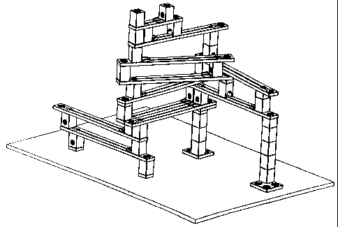
Figure 15 shows a complicated construction of the ball track. A plurality of
different ball paths is
implemented in a single construction. All the running rails lie horizontally
on the connecting ele-
ments or other running rails. In this way, and by means of the rotatable
fixing by means of the hol-
low or respectively solid cylinders and the bore sections 18, an extremely
stable construction is pos-
sible. In principle, there are no limits to the height of the ball track.
Providing sufficient running
tracks and connecting elements are available, metre-high constructions are
possible. The ball track
also does not necessarily have to be manufactured from wood. Ball tracks are
also conceivable that
of transparent materials, for example, plexiglass. In this way when coloured
balls or other rollable
elements are used, a visual effect is obtained.
The bridging element shown in Figures 16a) and 16b) serves to bridge through
bores on the running
tracks. If, for example, the ball paths are to be altered in an already
constructed ball track, a through
bore of a running track can very much get in the way. If the bridging element
is then placed in this
bore, a ball can pass along the running track over the bore. The bridging
element in this configura-
tion is provided with retaining arms 30 that prevent the bridging element
falling through the through
bore. Additionally, the bridging element also has a guideway for passing balls
and a projection 31
that ensure that the bridging element or respectively the guideway is
orientated parallel to the run-
ning track and twisting of the bridging element during use is excluded.
Clearly, the connecting
element shown in Figure 9 can also be as a bridging element. In this case, the
bridging element can
at the same time serve as a supporting point for a further running track.
A tipping element 33 is shown in Figures 18a), 18b) and 19. The tipping
element 33 can be put
with the aid of the guide tab 35 in a running track or onto a suitable
connecting element 34 so that it
lies on the bearing pivot 36. The tipping element has a substantially U-shaped
cross-section in the
longitudinal direction. The balls are guided into the tipping element such
that they arrive on the
surface 41 of the tipper box that is formed by the surfaces 40, 41 and the
limb surfaces of the U-
shape. By means of the random elements 42 that in this instance are
substantially semi-cylindrical,
CA 02360161 2001-07-19
- 22 -
the balls are guided into the tipper base. The configuration of the tipper
box, that is to say the
weight of the tipper box, ensures that in the empty state, the tipping element
is in the receiving posi-
tion, so that it is tipped clockwise about the bearing pivot 36 in Figures
18a) and b). Balls arriving
reach the tipper base and at first lie on the slightly inclined surface 40. If
the number of balls in the
tipper element 33 increases, ever more balls must assume a position that lies
to the left of the bear-
ing pivot or respectively bearing pivots 36 in the Figures. From a certain
number of balls onwards,
the receiving position of the tipper element becomes unstable, and it tips
about the bearing pivot 36
counter-clockwise to the left, and releases at least some of the balls. The
quarter cylinders 39 pre-
vent a plurality of balls jamming against one another in the tipper element
33. The guide elements
38 that are configured asymmetrically, ensure that when the balls are
released, the balls are consecu-
tively released onto, for example, running track. The tipper element has a
visual characteristic 37
that should make the player aware of the tipping capability of the tipper
element 33. The visual
characteristic can be, for example, be made using coloured markings.
The number of balls that the tipper element can receive until it becomes
unstable and releases at
least some of the balls again, is determined inter alia by the weight of the
tipper box. It is therefore
also possible for the advanced user to provide weights that can be mounted as
required in the tipper
boxes so that the user can influence the receiving capability of the tipper
element 33.
As described already, the tipper element 33 is principally designed to be
placed on a running track.
It is also possible, however, to place the tipper element 33 on special
connecting elements 34, that
are shown in Figures 20a) and 20b). The connecting element 34 has a guide slot
43 for receiving
the guide tab 35 and indentations for receiving the bearing pivot 36.
Figures 24a) and 24b) show a tipper element 50 with two receiving means,
wherein one is respec-
tively in the receiving position and the respective other one is in the
release position. In order to
make the manner of functioning clear, in Figure 25 a ball track is shown that
is provided with a tip-
per element 50 with two receiving devices. In the position shown, a ball
passing though the central
bore of the upper running track falls into the right-hand receiving means. As
soon as this position
becomes unstable, the tipper element tips in the clockwise direction, so the
right-hand receiving
CA 02360161 2001-07-19
-23-
means goes into the release position and releases the balls received to the
right onto the lower run-
ning track, while the left-hand receiving device goes into the receiving
position so that the balls now
falling though the central hole of the upper running track arrive in the left-
hand receiving means.
As can be seen in particular in Figures 24a) and 24b), the tipper element 50
has a separating wall 51
that is rotatable or respectively pivotable by means of the bearing pivot 52.
In addition two stops 53
are provided that limit the pivoting radius of the separating wall in order to
prevent complete open-
ing of the separating wall 51. In the configuration shown here, the separating
wall can be moved
simply on the basis of the intrinsic weight of the balls. The balls fall, for
example, in the position
shown in Figure 24a), into the right-hand receiving device. The balls are
pressed by gravity against
the separating wall 51, and the separating wall 51 moves to the left against
the stop 53 into the posi-
tion shown in Figure 24b). The receiving capacity of the receiving means can
easily be increased
using this clever construction, without the tipper element assuming overly
large dimensions. After
the right-hand receiving means has reached its maximum receiving capacity,
becomes unstable, and
goes into the release position, the following balls arrive in the left-hand
receiving means. Again, the
separating wall 51 is moved solely by the force of the weight of the balls,
but this time to the right
as far as the right-hand stop 53. In this position, the receiving capacity of
the left-hand receiving
means is increased, while at the same time the receiving capacity of the right-
hand receiving means
is reduced. The smaller capacity of the right-hand receiving means is
unimportant, however, as it is
in the release position anyway, and therefore cannot receive any balls at all.
In Figures 21a) and b), a spiral element 55 is shown. It is composed of a
running track section with
a ball guide 14 and through bores 15, and a spiral section that guides the
balls on a conical and spi-
ral-shaped path. The manufacturing of the spiral element 55 shown is very
simple. In an approxi-
mately ladle-shaped body, there is a continuous channel that nzns on the
running track section (cor-
responding to the ladle handle) parallel to the running track and in the
spiral section (corresponding
to the actual ladle) in a spiral shape. Using a suitable choice of material
(for example, wood), it is
possible, as shown in Figure 21b), to move the inner part of the spiral
section downwards. By
means of suitable supporting elements 48, the spiral section can be fixed in
its "extended" position.
The embodiment shown here has the further advantage that the supporting
elements 48 are mounted
in a fixed manner and depressions 46 are provided on the underside of the
spiral section, which de-
pressions serve to receive the supporting elements 48 in the storage position.
It is thus possible to
somewhat rotate the innermost "ring" of the spiral element in the
circumferential direction with
respect to the outer "rings" and to bring the supporting elements 48 into the
depressions 46. Secur-
ing elements 47 prevent accidental movements of the supporting elements 48.
CA 02360161 2001-07-19
-24-
The spacing element 45 provides stabilising. The guide elements 17' guide the
balls during particu-
larly critical travel on the track when entering and respectively leaving the
spiral element. It is par-
ticularly notable that the balls on the spiral element do not run in the
channel but on the tracks, so
they are retained only by the walls lying further out. Inward departure from
the tracks is prevented
by centrifugal force. By means of this extremely simple design of the ball
guideway, it is even pos-
sible to use such a spiral element as a "throw-in funnel". If, namely, the
balls are thrown if possible
in the right direction into the spiral section, the automatically find the
suitable path and are guided
inwards in a spiral shape. A connecting element with a side aperture or a
tipper element can also be
arranged above the spiral element such that the exit aperture is orientated
approximately in the di-
rection of an imaginary tangent on the spiral-shaped course of the ball.
The blocking element and the way it functions is shown in Figures 26 to 29.
The embodiment
shown here of the blocking element is composed of a body 54 that can also be
considered as a spe-
cially designed connecting element, and can also serve as one, and a trigger
device in the form of a
clapper 66, 67. Two exemplary arrangements of such a blocking element in a
ball track are shown
in Figures 29a) and 29b). It is conceived here that at least one ball path
runs such that balls arrive in
the upper aperture of the body 54. The balls are retained by the saddle 60 of
the clapper in the body
54. Only when a ball passes on the running track lying beneath, and deflects
the clapper 66, 67, is
just one ball released through the side aperture of the body. The clapper 66,
67 then swings back
and the passage through the body 54 is again blocked. As is clear from the two
exemplary ar-
rangements, the path running below the body 54 can be either a running track 2
with a horizontal
central section or a running track 3 with an inclined central section.
Clearly, the clapper 66, 67 must
where required be adjusted to the different distances apart of the adjacent
running tracks.
Figures 26a) and 26b) show the body 54 of the blocking element in detail. The
body has an upper
bore 18 and a side exit aperture 19. In addition a lower bore is also present,
through which the clap-
per 66, 67 can be guided into the body 54 and hung in a swinging manner. The
body 54 also has a
visual characteristic 37' that should make the user aware of the way the
blocking element works.
The swinging hanging of the clapper is indicated by the distinguishing mark
37'. The clapper 66,
67 is composed of the clapper arm 58, the pivot 57 and the saddle 60. The
pivots 57 serve for the
CA 02360161 2001-07-19
-25-
swinging hanging of the clapper 66, 67 in the body 54. For clarity, in Figure
28 a view through the
blocking element in its assembled state is shown. A ball that arrives in the
upper aperture 18 of the
body 54 firstly lands on the saddle 60 that has a concavely rounded saddle
surface 61. Here, the ball
is held securely and cannot leave the side exit aperture 19. If the clapper is
now diverted manually
or preferably by means of another ball in the direction of the arrow in Figure
28, the saddle 61
moves to the left, until it strikes with the section 63 against a section 64
of the body 54. In this posi-
tion the "hollow" of the saddle 61 is inclined far enough for the ball to
leave through the side exit
aperture 19. The clapper 66, 67 swings back and for the following balls,
passage is blocked again
until a following ball again diverts the clapper again and repeats the
procedure.
The embodiment of the blocking element shown here has a particularly clever
construction that re-
liably ensures that only one ball can leave the blocking element. The blocking
element is thus con-
figured according to the invention such that only when at least two balls are
located in the body 54,
actuation of the clapper 66, 67 ensures that a ball leaves the body 54 from
the side aperture 19. The
tipping of the saddle 60 is by itself not sufficient to move the lowest ball
in the body to the side exit
aperture, but rather the force of the weight of a further ball is additionally
necessary, that acts upon
the lower ball and presses the lower ball when the saddle 60 swings slightly
to the side in the direc-
tion of the surface 64 of the body. Only when the saddle swings back, the edge
63 of the saddle 60
presses the ball sideways out of the body 54. Any returning of the ball to its
original position is
impossible as this is prevented by the force of the weight of the subsequent
ball.
The saddle 60 has the shape shown in Figure 27c). In cross-section, the saddle
has a substantially
rectangular form, wherein the uppermost surface 61, as described hereinabove,
is concavely curved,
so that a kind of hollow or cavity forms in which a ball can be held securely.
It is clear from Figure
27c) that the height of the rectangle on the side facing the exit aperture is
greater than on the other
side, that is to say d2 < dl. The edge sections 62, 63 of the upper surface of
the saddle 60 are not
curved. As is also clear in Figure 27c), the surface 65 of the saddle 60
facing the exit aperture is not
completely arranged to run vertically, but has an incline. This incline is to
be matched with the in-
clined bearing surface 64 of the body 54.
CA 02360161 2001-07-19
-26-
Both embodiments of the clapper 66, 67 shown have an indentation that serves
to increase the
swinging range of the clapper, as thereby stopping of the clapper on the
hollow cylinder 16 of the
body 54 takes place only when there is larger diversion of the clapper 66, 67.
In particular when
small balls are used, or when the clapper 66 is arranged directly above a
through bore 15 of a run-
ning track, as is the case, for example, in Figure 29b), it is advantageous
when the clapper 66 has a
leading projection 59. In this way, diversion of the clapper 66 is increased.
As described hereinabove, the running tracks do not necessarily have to run in
a linear manner.
Thus, clearly, curved running tracks are also possible. For example, the
circular running tracks
shown in Fig. 30a) and 30b) can be used. The circular running tracks
particularly preferably have
six through bores 15, which are at the same distance apart in the
circumferential direction, so that
the running track describes a circle segment of 60 from one through hole to
the next. The embodi-
ment shown in Figure 30a) additionally has a non-curved running track section
that connects two
through bores 15 lying one on top of the other, and thus represents the
diameter of the circular path.
The non-curved running track section additionally has a centrally arranged
further through bore 15.
The circular running tracks desciibed can also be assembled from different
circle segment running
tracks. Such circle segment running tracks are shown in Figures 31 and 32.
Advantageously, these
can have a semi-circular notch 15' on at least one end section, and a hollow
half-cylinder 16' ar-
ranged substantially centrally thereto. In this way, these running tracks can,
for example, be com-
bined securely on the connecting elements. Figure 31 shows a 60 circle
segment running track 70
and Figure 32 a 120 circle segment running track 71. For increasing
variability, the running track
71 has a substantially centrally arranged bore 15. To reinforce the running
tracks, tabs 69 are pro-
vided that connect the two parts of the running track separated by a
continuous slot. Care must
clearly be taken that the tabs 69 do not obstruct the rolling balls. The
circular running tracks and
respectively the circle segment running tracks can also have guides, as shown
in Figures 30b) and
32b).
Circular constructions are possible with the aid of these running tracks,
wherein as is shown for
example in Figure 33b), the circular paths in the individual planes can also
be arranged offset later-
CA 02360161 2001-07-19
-27-
ally with respect to one another. Alternatively, or in combination with this,
wave-shaped track
courses can also be formed. By means of the additional curved running tracks,
there are almost no
limits to the imagination when forming the most varied layouts. Thus, for
example, ball tracks can
also be implemented whose layout represents one or more letters of the
alphabet.
The radius of the circular running tracks 68 and respectively the radius of
curvature of the circle
segment running tracks 70, 71 advantageously corresponds to the effective
length of at least some of
the running tracks. The effective length of the running tracks is understood
to be the distance be-
tween two, not necessarily adjacent, through bores 15 of the running tracks. A
60 circle segment
running track then necessarily has the same effective length.
It is moreover also possible to couple two circle segment running tracks
directly to one another so
that the tracks overlap. The connecting element can be omitted as in general
the height difference to
be overcome is sufficient, due to the thickness of the tracks, to give the
ball the necessary horizontal
speed component. Particularly preferably, the circle segment running track
thus has an indentation
72 that simplifies the crossing of the ball from one circle segment running
track to the next. This is
shown in Figures 34a) and 34b).
In Figures 35a) and 35b) respectively, a branching circle segment is shown. In
both instances a
diverting element 73 is arranged in approximately the centre of the Y-shaped
running track, with the
aid of which switching can be carried out back and forth between different
ball paths. The distance
apart of two through bores of the Y-shaped running tracks is here selected
such that they can be
installed as 60 circle segment running tracks into the ball path. This
running track can, however be
built into the ball path in principle at any point desired. By swinging over
or respectively by divert-
ing the diverting mechanism 73, the ball course is altered. In principle, this
running track is also
playable from all sides. In some instances, it can be necessary, however, that
the retuming ball ac-
tuates the diverting mechanism 73. In Figure 35b), the diverting mechanism 73
is configured as a
bar arranged in a pivoting manner. The bar is mounted by one side in a
pivoting manner about a
point of rotation. In addition, end stops 75 are provided that are to prevent
overly wide diversion of
the bar 73. The embodiment of the diverting element 73 in Figure 35a) has a
wedge 73 that is pivo-
CA 02360161 2001-07-19
-28-
table about the axle 74. The axle 74 is arranged in the plane of the tracks,
so that the axle 74 runs
substantially horizontally. Clearly, such branching cannot only be used in
circle segment running
tracks.
It is clearly evident that with the present ball track, there is practically
no limit to the imagination.
Constructions with any layout are possible. It is also left to the user as to
whether a connecting ele-
ment must follow a running track, and vice-versa, or whether running track is
placed on running
track, or respectively connecting element on connecting element. The
variability obtained with the
present invention ensures that children of all ages and in many cases even
adults, will have pleasure
using the ball track.