Note : Les descriptions sont présentées dans la langue officielle dans laquelle elles ont été soumises.
CA 02360245 2001-10-26
- 1 -
Method for testing a heating system
The invention concerns a method for testing a heating sys-
tem with at least one basic unit, which controls activat-
ing elements of individual heating circuits, the basic
unit being connected with setting units by way of signals.
In many cases, floor heating systems are designed so that
the individual heating circuits, that is; pipes, which are
arranged in the floor, receive the heating fluid, usually
hot water, from a distributor, activating elements, usu-
ally valves, being arranged in the distributor. The dis-
tributor receives the heating fluid from a heat source,
for example, a district heating net, or a heat exchanger
connected with a district heating net, or a boiler. The
control of the distribution of the heating fluid to the
individual heating circuits occurs via the activating ele-
ments, which are for this purpose controlled by a basic
unit. This basic unit, again, receives signals from set-
ting units, for example room thermostats.
Another heating system uses radiators, through which heat-
ing water can also flow, to supply heat to the room to be
heated. Such radiators are controlled by valves, which are
arranged direct on the radiator. A commonly used control
has thermostatically operate valves, in which the desired
value is, for example, preset by turning a handle. A fur-
ther development enables a user to change the desired
value also without turning the handle, for example by
means of timed or remote control, the remote control sig-
nals coming from the basic unit.
t CA 02360245 2001-10-26
- 2 -
Contrary to heating systems, which are exclusively con-
trolled by manually controlled radiator thermostats, it is
practically impossible for the installer to perform a com-
plete check of the heating system at a reasonable cost and
effort. Therefore, the check is normally limited to a
pressure check, to find out if the heating pipes are
tight, and a visual check to make sure that the individual
heating pipes are connected correctly. For the control of
the heat distribution, that is, the cooperation between
the setting units; the distributor, if any; the activating
elements and the basic units, however, such testing possi-
bilities do not exist. Of course, the installer can test,
if the floor in a room becomes warm. Due to the relatively
large thermal inertia, however, it is extremely difficult
to find out, if a certain thermostat controls the correct
heating circuit, or if the basic unit contacts the "cor-
rect" thermostat. The installer, therefore, often leaves a
system without being certain that it is correctly in-
stalled and works satisfactorily.
The invention is based on the task of simplifying the
testing of a floor heating system.
With a method as mentioned in the introduction, this task
is solved in that the elements available in the heating
system are arranged hierarchically in steps, these steps
being tested one after the other in a predetermined order.
With this method it is possible to perform a systematic
test of a floor heating system with regard to faults. The
installer can then work his way through the individual hi-
erarchical levels. Dividing the elements into individual
hierarchical levels makes it easier for the installer to
CA 02360245 2001-10-26
- 3 -
maintain the overview, leaving out none of the testing
steps.
It is particularly preferred that the test of a step does
not begin, until the test of superior step has indicated a
faultless state. Thus, it is ensured that the installer
cannot omit a step, as the test of a hierarchically lower
step cannot start, until the test of the hierarchically
higher step has been successfully finished. This stepwise
method has several advantages. Firstly; it is ensured that
the starting conditions for the lower step are faultless.
Thus, faults on elements, which are not caused by faults
in these elements but by faulty starting information, can-
not be indicated by accident. Secondly, the elements of
the lower step can work with faultless starting condi-
tions, so that the tests are made under realistic condi-
tions. Finally, the installer is also compelled to remedy
any faults completely, as otherwise, he cannot go on with
the test.
25
It is preferred that during a first part it is tested, if
the elements are installed correctly, and during a second
part, if the elements work in a predetermined way. During
installation, faults may occur for several reasons. When
testing first, if the elements have been installed cor-
rectly, the test can be limited to a certain area of fault
reasons, namely the installation, that is, mounting and
connection of the elements in questions. After having made
sure that the elements are installed correctly, the next
step can be started, namely testing, if the elements work
in the predetermined way. This simplifies the fault find-
ing.
CA 02360245 2001-10-26
- 4 -
Preferably, the occurrence of a fault is indicated by way
of kind and location of the fault. This makes it easier
for the installer to remedy the fault. The location can
virtually mean the physical spot, in which the element is
arranged. In many cases, however, it is sufficient to
state, in which step the fault has occurred, as the in-
staller knows the elements available in this step, and the
number of elements per step is limited.
Preferably; it is tested, if the number of r_h_e connected
setting units corresponds to the number of the setting
units signed in. This is a simple, but effective way of
testing. During the installation, the basic unit must be
informed about the number of setting units, from which in-
formation must be expected. For this purpose, these set-
ting units are signed on to the basic unit, for example in
that the basic unit is informed about an address, under
which the setting unit in question can be recognised. How-
ever, then a physical connection has to be allocated to
each setting unit. The number of connections must corre-
spond to the number of setting units signed in. The method
applies for setting units, which control the heat distri-
bution in a floor heating system, and which are, there-
fore, usually arranged in a distributor, as well as for
radiator valves, which are arranged direct on the radia-
tors.
Preferably, it is tested, if with a wireless connection
between the setting units and the basic unit a signal
strength of received signals of a predetermined minimum
value is obtained. In the past, floor heating systems of-
ten did not have a comfortable setting opportunity, that
is, the user or consumer merely had the chance of changing
CA 02360245 2001-10-26
- 5 -
a valve position on the distributor. The subsequent fit-
ting of thermostatic elements or other setting devices in
the individual rooms is therefore difficult, when it com-
prises the running of cables. When, however, wireless con-
s nections between the setting units and the basis are cho-
sen, the problem of having to run cables through the whole
apartment does not arise. The signal transmission then
takes place by means of electro-magnetic waves, infrared,
or ultrasonic or some other kind of wireless transmission.
In this case, however, it must be ensured t-h-at r_he cor?_r~ec-
tions between the individual setting units and the basic
unit have a signal strength, which is sufficient for a re-
liable transmission of the information. When this is not
the case, a fault is reported. This method also applies
for wireless, remote-controlled radiator thermostats,
which are signed in on the basic unit, upon which the ba-
sic unit knows that such a radiator thermostat should be
available. If such a radiator thermostat is signed in, but
cannot be "found" by the basic unit, for example because
of insufficient signal strength, a fault is reported.
It is preferred that, in case of insufficient signal
strength, an amplifier is arranged on a path between the
setting unit and the basic unit. An amplifier of this
kind, also called "repeater" or "rooter", receives the
signal from the setting unit and sends it on in an ampli-
fied form to the basic unit or vice versa. In this case,
the installer is not only alerted on the fault, he also
gets a solution proposal.
It is particularly preferred that the amplifier is signed
in on the basic unit. The basic unit then knows that an
amplifier is available.
CA 02360245 2001-10-26
- 6 -
This is particularly advantageous, when, during operation,
the strength of the received signals is tested continu-
ously or from time to time, and, when found too weak, the
signal of the setting unit in question is led via an
available amplifier. When, for example, modifications are
going on in the house, or furniture is rearranged, the
transmission conditions can change. This will be estab-
lisped by means of a repeated or continuous measuring of
the signal strength-, In many cases, it is t_h_en ,_,_ot Atren
necessary to install a new amplifier. Due to the signing
in, the basic unit is aware that an amplifier is available
in the area. It then leads the signals of the setting unit
transmitting the too weak signals through this amplifier,
so that the signal level becomes sufficient again.
Preferably, the voltage supply to the setting units is
tested. This is particularly advantageous, when the indi-
vidual setting units, for example thermostatic elements,
are supplied with voltage via a battery. In this case, a
battery voltage meter can provide information about the
state of the battery, so that information is given, when
the battery must be replaced, or when it does not work op-
timally already during mounting.
Preferably, it is tested, if the activating elements can
be contacted and are working. Here again, the testing is
divided in two, namely one test to make sure that the sig-
nal actually reaches the activating elements and one to
make sure that the activating element in question reacts
when a signal occurs. For this purpose, for example, a
position measuring in the activating element, a current
measuring or the like, can be used.
CA 02360245 2001-10-26
_ '~ _
It is also advantageous, in connection with a flow tem-
perature control of the distributor it is tested, if sen-
sors for the detection of flow and return temperatures are
available and working. This test is relatively simple.
Preferably, it is tested, if a regulating unit for influ-
encing the flow temperature is available, can be contacted
and is working. Also here, a reaction of the regulating
1 !~ ynit i a tegted ga~ra_ral timeg ~ gp t_h-at ~ fapl t i g mp-ra_ a_~g-
ily recognisable with regard to kind and location, if any.
In the following, the invention is described on the basis
of a preferred embodiment in connection with the drawing,
showing:
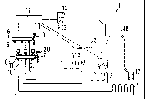
only Fig.. a schematic view of a floor heating system
A floor heating system 1 has several heating circuits 2,
3, 4, which are arranged in the floor in the shape of
looped pipes. In the following description, it is antici-
pated that each heating circuit 2, 3, 4 heats one room.
However, it is also possible to arrange several heating
circuits in one room.
Further to the heating circuits 2, 3, 4, which are in the
form of floor heating systems, the heating system shown in
the figure can also comprise radiators, which are not
shown in detail. Of these radiators, at least one is con-
trolled via a wireless radiator thermostat, that is, the
radiator thermostat receives information, which are de-
scribed below, via a wireless path, that is, via radio or
infrared light.
CA 02360245 2001-10-26
_ 8 -
The supply to the heating circuits 2, 3, 4 takes place via
an inlet distributor 5, which is connected with a source
for a heat transfer fluid shown by means of an arrow 6,
for example, a district heating net.
The outlet of the heating circuits 2, 3, 4 is connected
with an outlet distributor 7, which returns the heat
transfer fluid to the fluid source, here shown by means of
an arrow 8. Together, the inlet distr,'_buto_r 5 and the out-
let distributor 7 form a distributor. In the outlet dis-
tributor 7, an activating element 9, 10, 11 is provided
for each heating circuit 2, 3, 4, the activating elements
being controlled by a basic unit 12. Of course, the acti-
vating elements 9, 10, 11 can also be placed in the inlet
distributor 5.
The basic unit 12 is connected with a zone control unit 14
via an electrical cable 13. By means of the zone control
unit 14, it is possible to join different rooms to zones,
and to run a predetermined heating programme in each zone.
A heating programme of this kind could, for example, com-
prise a night-setback, the week-end setback differing from
the weekday setback.
Further, a room thermostat 15, 16, 17 is arranged in each
room, the room thermostats 15, 16, 17 having a wireless
connection with the basic unit 12. An information trans-
mission from the basic unit to the individual room thermo-
stats 15, 16, 17 takes place by means of electromagnetic
waves, for example radio.
CA 02360245 2001-10-26
_ g _
The room thermostat 17 is too far away from the basic unit
12, so that the signal strength for the radio transmission
is not sufficient to ensure a reliable information trans-
mission. Therefore, an amplifier 18 is arranged between
the basic unit 12 and the room thermostat 17, the ampli-
fier 18 also being called "rooter" or "repeater"
Further, on the distributor 5, 7 valves 19, 20 are ar-
ranged, by means of which the flow temperature can be set.
The valves 19. 20 are also connected with temperaturA sen-
sors.
When an installer has finished the system, he has mounted
and mutually connected the individual elements. In this
case, he wishes to test, if the plant or the heating sys-
tem works faultlessly. Due to the relatively large thermal
inertia of a floor heating, it is, for example, relatively
difficult to test, if the room thermostat 15 actually in-
fluences the heating circuit 2 in the desired way.
When the installer now starts such a test, for example by
pressing a "test button" on the basic unit 12, the indi
vidual elements of the heating system 1 are tested in ac-
cordance with the following method:
First, the individual elements are arranged hierarchically
in steps. The upper step is, for example, made up of the
basic unit 12, the next step then comprises the zone con-
trol unit 14 and the room thermostats 15 to 17. The dis-
tributor 7 with the activating elements 9 to 11 and the
valves 19, 20 then form the third step. Of course, this
division can also be made even more detailed.
CA 02360245 2001-10-26
- 10 -
During testing, it is firstly controlled, if the basic
unit 12 works faultlessly. For this purpose, internal rou-
tines can be performed, which are known per se for such
units. Only when it has been established that the basic
unit works faultlessly, the test of the elements in the
next step is started. Firstly, it is tested, if in fact a
connection to the zone control unit 14 exists. This may,
for example, be tested by means of a current flow. In con-
nection with the room thermostats 15 to 17, it is tested
whether or not a radio connection can be establ_,'_shed, riot
until it has been ascertained that a connection exists, it
is tested, if the elements work in a predetermined way.
For the room thermostats 15 to 17, this test can, for ex-
ample, be made in that a desired value for these room
thermostats 15 to 17 is changed, after which it is con-
trolled whether or not a corresponding control signal is
returned to the basic unit 12.
When, for example, it is established that in a certain
case a control signal is not returned, or is not returned
in a proper manner, this fault is reported. At the same
time, a reference to the element in question, for example
the room thermostat 17, is obtained.
When, for example, it turns out that the signal from the
room thermostat 17 is too weak, the installer is informed
accordingly. He then knows (or is informed) that the am-
plifier 18 must be inserted to obtain a sufficiently
strong signal from the room thermostat 17.
During installation, the individual room thermostats 15,
16, 17 are signed in on the basic unit 12. Also the zone
control unit 14 has been signed in. All elements receive
CA 02360245 2001-10-26
11
an address or sign in on the basic unit 12 with their ad-
dress, so that the basic unit 12 "knows" the communication
partners, with which it must work. When an amplifier 18 is
installed, it is signed in too.
During the test procedure, it is now tested, if the number
of elements signed in corresponds with the number of ele-
ments, with which a connection can be established. If this
is not the case, a fault is reported.
The next step is not tested, until it has been established
that all room thermostats 15 to 17, the amplifier 18 and
the zone control unit 14 work correctly. For this purpose,
the basic unit 12 activates the operating elements 9 to
11, that is, valves, and it is established, if a corre-
sponding reaction occurs. First, however, it is examined,
if the signals do at all reach the corresponding elements.
If this is not the case, the installer merely has to check
the pipe. When the signals do arrive, a movement, however,
does not occur, this indicates another fault. The movement
can, for example, be measured by means of a position meas-
uring, a current measuring or something else.
In a similar way, also the valves 19, 20 for setting the
flow temperature can be tested. Also here, it is expedient
to perform the test in several steps, that is, first it is
checked, if the element in question is available, then, if
a signal reaches the element, and finally, if the element
reacts in the desired way.
The method is not limited to the start-up, that is, test-
ing after installation. It can also be performed from time
CA 02360245 2001-10-26
- 12 -
to time during operation, or it can be performed continu-
ously.
When, for example, the receiving conditions in a house
change, as shown by means of the dotted-line box 21, which
is placed in the transmission path of the room thermostat
16 and shades the electro-magnetic waves, the basic unit
12 establishes that the received output is too weak. How-
ever, it "knows" that the amplifier 18 is arranged near
the room thermostat 16. It therefore diverts the signal
of the room thermostat 16, so that they pass the amplifier
18.
Further, the batteries in the individual room thermostats
15 to 17 can be tested, and a warning be displayed, when
the voltage drops below a predetermined value, that is,
the battery must be replaced.
The test routine also offers the opportunity of displaying
the temperature in the individual rooms, so that it ap-
pears, if the temperature displayed corresponds to the
temperature expected in the room in question. If this is
not the case, something can be wrong with the room thermo-
stats 15 to 17.