Note : Les descriptions sont présentées dans la langue officielle dans laquelle elles ont été soumises.
CA 02362741 2001-09-04
WO 00/53410 I PCT/GB00/00862
TITLE
LAMINATED GLAZINGS
BACKGROUND OF THE INVENTION
1. Field of the Invention
This invention relates to laminated glazings and in particular to bullet
resistant glazings.
2. Summary of Related Art
Bullet resistant glazings comprise a laminated structure that includes
multiple glass
plies and at least one impact resistant ply. These glazings may be installed
in vehicles and to
facilitate installation the glazing may be provided with a step adjacent its
periphery, the step
extending around part or all of the periphery. The step results from one or
more of the plies
extending beyond the remaining plies, and in this specification the ply or
plies which thus
extend beyond the others will be referred to as the "outer layer". The outer
layer normally
has a greater peripheral dimension than the remaining plies and is usually a
single glass ply,
which may be annealed, semi-toughened or toughened, but it may also comprise a
laminate
such as two glass plies bonded by a suitable plastics layer or layers. The
"step" of the outer
layer enables the glazing to be fitted into the glazing channels of vehicle
openings. However,
the outer layer must be thick enough in order to possess the structural
strength to support the
weight of the glazing when fitted into the vehicle opening and to resist
dynamic loadings that
occur when the vehicle is in motion or the step is likely to be damaged, which
may result in
the body of the glazing breaking away from the step and falling out of the
vehicle opening.
Furthermore, the application of a conventional ceramic obscuration band around
the periphery
of the glazing (which will inevitably cover at least part of the step) weakens
the glass covered
by the obscuration band thereby reducing the structural strength in the
stepped region.
Bullet resistant glazings used in vehicles may have a thickness up to 70 mm or
more
and a consequence the outer layer may be up to 9 mm thick or more. In some
specialist
vehicles (e.g. military vehicles) where ballistic protection is required, the
thickness of the
glazing channels may be set during manufacture of the vehicles at the required
thickness to
accommodate the bullet resistant glazing. However, there are instances where
bullet resistant
glazings are installed into mass-produced vehicles and it is not practical to
change the tooling
used in the manufacture of the vehicle bodywork to alter the width of the
glazing channels
CA 02362741 2001-09-04
WO 00/53410 2 PCT/GB00/00862
from conventional thicknesses to greater thicknesses so as to accommodate
bullet resistant
glazings. As a consequence these vehicles are individually adapted to
accommodate the
bullet resistant glazings and this may be very expensive.
It would be desirable to provide a bullet resistant glazing suitable for
installation in
glazing channels of conventional thicknesses.
SUMMARY OF THE INVENTION
According to the invention there is provided a laminated bullet resistant
glazing
comprising a plurality of glass and plastics plies arranged in at least two
layers including an
outer layer and an inner layer, wherein the outer layer extends beyond the
inner layer so as to
form a step which extends around at least part of the periphery of the
glazing, and wherein the
glazing is reinforced with a band at least partially positioned on the step,
the band having at
least first and second longitudinal faces wherein the first longitudinal face
is in contact with
the step and the second longitudinal face is in contact with an adjacent
portion of the glazing.
The band enhances the support strength of the outer layer of the glazing and
enables the
manufacture of a bullet resistant glazing with the outer layer being reduced
in thickness.
Such a glazing may be accommodated in conventional automotive glazing systems
of mass
produced vehicles which have standard glazing channels which are less than
about 6 mm
thick.
The band is preferably comprised of a ballistic resistant material which
additionally
provides ballistic protection around the stepped region of the glazing which
traditionally has
been ballistically weak, and reduces or prevents spall, which results from
breakage of the
step, entering the interior of the vehicle.
The band may be comprised of metal or alternatively from a fibre reinforced
material.
Preferably the fibre is an aramid fibre.
The band may be of angled construction, i.e. comprising two strips which meet
at an
angle. The strips may be joined at right angles with a longitudinal face of
the first strip
mounted on the step and a longitudinal face of the second strip mounted on the
periphery of
the adjacent plies. This arrangement further enhances the support strength of
the outer layer.
At least part of the band may be embedded in an interlayer which bonds the
outer layer
to the inner layer. Such an arrangement further enhances the support strength
of the outer
layer.
CA 02362741 2001-09-04
WO 00/53410 3 PCT/GB00/00862
The embedded part of the band may have a thickness in cross-section less than
that of
the remainder of the band. Such a band may be accommodated between the outer
and inner
layers of the glazing without having to alter the thickness of the plastic ply
or plies (or
interlayer) which bonds these layers.
Preferably the face of the band mounted on the step is co-extensive therewith.
An adhesive may bond the band to the glazing and preferably the adhesive is
polyurethane.
The thickness of the band may be in the range 2 to 16 mm and is preferably in
the range
2 to 4 mm. The combined thickness of the step and the band may be in the range
5 to 30 mm.
DESCRIPTION OF THE DRAWINGS
Embodiments of the invention will now be described with reference to the
accompanying drawings in which:
Figure 1 is a fragmentary cross section of a laminated glazing in accordance
with a first
embodiment of the invention.
Figure 2 is a fragmentary cross section of a laminated glazing in accordance
with a
second embodiment of the invention.
Figure 3 is a fragmentary cross section of a laminated glazing in accordance
with a third
embodiment of the invention.
Figure 4 is a fragmentary cross section of a laminated glazing in accordance
with a
fourth embodiment of the invention.
Figures SA to SC are cross sections of stepped glazing samples tested to
assess the
structural strength in their stepped region.
Figure 6 is a schematic cross section of a stepped glazing sample and test
apparatus
used to assess the structural strength of the sample's stepped region.
DESCRIPTION OF THE PREFERRED EMBODIMENTS
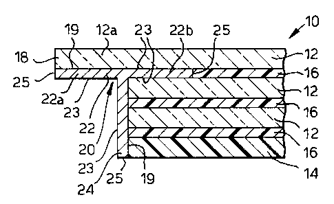
Referring to the drawings a laminated glazing generally designated 10
comprises glass
plies 12 and an impact resistant ply 14, such as polycarbonate, bonded by
flexible plastics
interlayers 16 such as polyvinylbutyral or polyurethane. The outer glass ply
12a of the
glazing has a step 18 which is formed around at least part of the periphery of
the glazing. In
fixed windows, such as a windscreen or a backlight, the step may extend around
the whole
periphery of the window, and in opening windows the step may or may not extend
around the
edge of the window that can be exposed.
CA 02362741 2001-09-04
WO 00/53410 4 PCT/GB00/00862
The glazing 10 further comprises a reinforcing band 20, which is coextensive
with the
step 18. In Figure 1 the reinforcing band comprises strips 22 and 24 having
longitudinal faces
23 and end faces 25. Strips 22 and 24 are joined at right angles such that in
use a longitudinal
face of first strip 22 is mounted on the step and a longitudinal face of
second strip 24 is
mounted on the periphery of the inner plies of the glazing. The band may be
adhered to the
glazing by applying a suitable adhesive 19, such as sheet polyurethane,
between the band and
the glazing and bonding may occur during the autoclave cycle used to laminate
the plies of
the glazing.
In Figure 2 a different design of reinforcing band is shown which is of T
shaped cross
section and comprises a first strip 22 having ends 22a and 22b, and a second
strip 24 joined at
right angles to the first strip 22. The end 22b of first strip 22 is embedded
in the interlayer
which bonds the outer glass ply 12a to its adjacent glass ply. With end 22b of
the band
embedded in the interlayer, the band is somewhat fixed in position and may be
further fixed
in position by applying an adhesive 19 between the band and the glazing as
hereinbefore
described.
A further alternative form of design of reinforcing band 20 is shown in Figure
3 which
is substantially planar and partly embedded in the interlayer which bonds the
outer glass ply
12a to its adjacent glass ply. An adhesive 19 may be applied between the band
20 and the
step 18 to adhere the band to the glazing as hereinbefore described.
Figure 4 shows a still further design of reinforcing band 20 in which the band
is
provided with a stepped region 26 (i.e. a region thinner in cross section than
the remainder of
the band) which is embedded in the interlayer 16 which bonds the outer glass
ply 12a to its
adjacent glass ply. Preferably the interlayer comprises more than one layer
and in Figure 4 it
comprises a polyurethane layer 16a and polyvinylbutyral layer 16b. The stepped
region 26 of
the band 20 is sufficiently thin enough that it can be accommodated between
layers 16a and
16b without the need for altering the thickness of any of the layers of the
multi-layer
interlayer. This arrangement allows band 20 and interlayer 16 to overlap
thereby enhancing
the strength of this part of the glazing.
The thickness of a reinforcing band used in the present invention, shown as
dimension p
in Figure l, may be in the range 2 to 16 mm and is preferably in the range 2
to 4 mm, and the
thickness of the stepped region in a glazing according to the present
invention, shown as
CA 02362741 2001-09-04
WO 00/53410 5 PCT/GB00/00862
dimension q in Figure l, may be in the range 5 to 30 mm and is preferably in
the range 5 to 16
mm. The thickness of the stepped region 26 of the band 20 may be as low as 0.4
mm or less.
In order to demonstrate that the application of a reinforcing band around the
step
increases the structural strength in the stepped region, a number of
representative samples
were constructed for testing as shown in Figure 5. Samples A, B, C 1 and C2
(shown in
Figures 5A, 5B and 5C respectively) each comprise an outer soda lime annealed
glass ply 40
which is 500 mm in length, 50 mm wide and 6 mm thick, and an inner glass ply
42 which is
380 mm in length, 50 mm wide and 6 mm thick bonded by a 5 mm thick PVB
interlayer 44.
The step 18 in each sample was therefore 120 mm in length (shown as dimension
x) and 50
mm wide. In Sample B a reinforcing material 20 comprising a metal plate of
dimensions
120 mm x 50 mm and 2.5 mm thick was bonded to the step by 1.25 mm thick sheet
polyurethane 19 and laminated during the autoclave cycle used to laminate the
glass plies. In
Sample C1 a similar sized plate was similarly bonded to the step but arranged
so as to be
embedded 20 mm into the PVB interlayer 44. The metal plate 20 in Samples B and
Cl
comprised 13°lo manganese steel plate having a tensile strength of 800 -
1130 N mm-~, and is
available from Sleeman Engineering FRC Ltd of Wednesbury, England. Sample C2
was
constructed similar to that of Sample C1 except that the reinforcing material
20 comprised a
multilayer neoprene binded aramid fibre of 3 mm thickness available from
Verseiding Indutex
of Stalybridge, Cheshire, England and was bonded to the step by 0.38 mm sheet
polyurethane.
In this particular sample the aramid fibre was Kevlar (trade mark) which was
weaved into a
mat and impregnated with a neoprene binder. Each sample was allowed to
temperature
stabilise at 18°C for 24 hours before testing.
In turn each sample 50 (A, B, Cland C2) was tested on an arrangement as shown
in
Figure 6. Each sample was placed on two knife edge supports, 52, each being 10
mm inboard
from the sample edges. A knife edge load applicator 56 and an associated
weight tray 58 was
arranged at load point 60 and weights were increasingly added to the weight
tray until the step
broke from the body of the sample. Breakage occurred for Sample A at 22 kg,
for Sample B
at 28 kg, for Sample C1 at 48 kg and for Sample C2 at 24 kg. It was also noted
that in
Sample A the step broke away completely from the body of the sample, whilst in
Samples B,
C 1 and C2 although the glass step broke, the reinforcing material 20 retained
attachment to
the body of the sample.
CA 02362741 2001-09-04
WO 00/53410 6 PCT/GB00/00862
From these results it is clear that the application of a reinforcing band to
the step
significantly increases the structural strength in this area and enables the
manufacture of a
bullet resistant glazing having an outer layer reduced in thickness compared
to prior bullet
resistant glazings. Furthermore, as the reinforcing material remained attached
to the body of
the sample once the step had broken, a glazing having a band mounted on the
step in a similar
fashion to that described with reference to the Samples, will be retained in
the vehicle
opening after the step has broken or been fractured.
The band is preferably comprised of a ballistic resistant material which
additionally
provides ballistic protection around the stepped region of the glazing which
traditionally has
been ballistically weak, and reduces or prevents span, which results from
breakage of the
step, entering the interior of the vehicle.
It will be appreciated that other fibre reinforced materials in addition to
aramid fibre
reinforced materials may also be suitable materials from which the band 20 may
be formed,
for example polyethylene fibres mixed with an elastomeric binder (such as
neoprene or
polyurethane) and examples of such materials are Dyneema (trade mark)
available from DSM
High Performance Films of Holland and Spectra (trade mark) available from
Allied Signal
Corporation of USA.
A particular advantage of using a reinforcing band which comprises a
multilayer fibre
impregnated with a binder is in its ease of processing in the manufacture of
laminated
glazings, and in particular those which are curved. Such a band may be
appropriately
positioned in the lay up to be laminated and does not require to be bent (to
conform to the
curvature of the laminated glazing) prior to lamination. Preferably the
multilayer material is
impregnated with a polyurethane binder and such a material (which comprises an
aramid fibre
impregnated with a polyurethane binder) is available from Verseiding Indutex
of Stalybridge,
Cheshire, England and bonding occurs during the autoclave cycle used to
laminate the plies of
the glazing. Additionally, in the embodiment of Figure 4 the stepped region 26
of the band 20
may be formed by at least one layer of the multilayer stack extending beyond
the remaining
layers.
It will be appreciated that known technical features may be incorporated into
the
glazing. For example a layer resistant to scratching and abrasion may be
applied to the inner
face of the impact resistant ply to enhance its surface durability.
Furthermore, the glazing
CA 02362741 2001-09-04
WO 00/53410 7 PCT/GB00/00862
may be substantially flat or curved and it may contain at least one ply with
solar control
properties.