Sélection de la langue

Search

Sommaire du brevet 2362902 

Énoncé de désistement de responsabilité concernant l'information provenant de tiers

Une partie des informations de ce site Web a été fournie par des sources externes. Le gouvernement du Canada n'assume aucune responsabilité concernant la précision, l'actualité ou la fiabilité des informations fournies par les sources externes. Les utilisateurs qui désirent employer cette information devraient consulter directement la source des informations. Le contenu fourni par les sources externes n'est pas assujetti aux exigences sur les langues officielles, la protection des renseignements personnels et l'accessibilité.

Disponibilité de l'Abrégé et des Revendications

L'apparition de différences dans le texte et l'image des Revendications et de l'Abrégé dépend du moment auquel le document est publié. Les textes des Revendications et de l'Abrégé sont affichés :

  • lorsque la demande peut être examinée par le public;
  • lorsque le brevet est émis (délivrance).
(12) Demande de brevet: (11) CA 2362902
(54) Titre français: LENTILLE D'OBJECTIF
(54) Titre anglais: OBJECTIVE LENS
Statut: Réputée abandonnée et au-delà du délai pour le rétablissement - en attente de la réponse à l’avis de communication rejetée
Données bibliographiques
(51) Classification internationale des brevets (CIB):
  • G11B 07/1374 (2012.01)
(72) Inventeurs :
  • MIURA, KAZUO (Japon)
(73) Titulaires :
  • SONY COMPUTER ENTERTAINMENT INC.
(71) Demandeurs :
  • SONY COMPUTER ENTERTAINMENT INC. (Japon)
(74) Agent: MBM INTELLECTUAL PROPERTY AGENCY
(74) Co-agent:
(45) Délivré:
(86) Date de dépôt PCT: 2000-02-18
(87) Mise à la disponibilité du public: 2000-08-24
Licence disponible: S.O.
Cédé au domaine public: S.O.
(25) Langue des documents déposés: Anglais

Traité de coopération en matière de brevets (PCT): Oui
(86) Numéro de la demande PCT: PCT/US2000/004327
(87) Numéro de publication internationale PCT: US2000004327
(85) Entrée nationale: 2001-08-16

(30) Données de priorité de la demande:
Numéro de la demande Pays / territoire Date
11/42408 (Japon) 1999-02-19

Abrégés

Abrégé français

L'invention concerne une lentille d'objectif (1) partagée par différents types de disques optiques utilisant différentes longueurs d'ondes, dans laquelle sont évités les dégâts causés par des collisions entre le disque et la lentille. Un élément protecteur (1b) est placé sur toute la périphérie ou sur une partie de la périphérie d'une protubérance protectrice (1p) de la lentille d'objectif (1). L'élément protecteur (1b) peut remplacer la protubérance protectrice (1p).


Abrégé anglais


In an objective lens (1) shared by various kinds of optical disks using
different wavelengths, damage due to collision between the disk and lens is
avoided. A protective member (1b) is provided in the entire periphery or in a
part of the periphery of a protective protrusion (1p) of the objective lens
(1). The protective member (1b) may replace the protective protrusion (1p).

Revendications

Note : Les revendications sont présentées dans la langue officielle dans laquelle elles ont été soumises.


-6-
WHAT IS CLAIMED IS:
1. An objective lens for focussing a plurality of laser beams having different
wavelengths onto an optical disc, comprising:
a lens with a main body;
a convex surface;
a protective protrusion formed on the lens at least partially around the lens
main
body; and
a protective member attached to at least a portion of the protective
protrusion;
wherein at least a portion of the protective protrusion or of the protective
member
extends beyond a plane that is tangent to the apex of the lens convex surface.
2. The objective lens of claim 1, wherein:
the protective member is provided at least partially around the periphery of
the
convex surface.
3. The objective lens of claim 1, wherein;the protective member is made at
least
partially of rubber.
4. The objective lens of claim 1, wherein:
the protective member is made at least partially of plastic.
5. The objective lens of claim 1, wherein:
the protective protrusion and protective member are substantially circular in
shape.
6. The objective lens of claim 1, wherein:
the protective member comprises a multiplicity of segments attached to the
protective protrusion.

-7-
7. The objective lens of claim 6, wherein:
the protective member is made at least partially of rubber.
8. The objective lens of claim 6, wherein:
the protective member is made at least partially of plastic.
9. An objective lens for focussing a plurality of laser beams having different
wavelengths onto an optical disc, comprising:
a lens with a main body;
a convex surface; and
a protective member attached to at least a portion of the lens main body
around at
least a portion of the periphery of the lens convex surface;
wherein at least a portion of the protective member extends beyond a plane
tangent
to the apex of the lens convex surface.
10. The objective lens of claim 9, wherein:
the protective member comprises a multiplicity of segments attached around the
periphery of the lens convex surface.
11. The objective lens of claim 9, wherein:
the protective member is made at least partially of rubber.
12. The objective lens of claim 9, wherein:
the protective member is made at least partially of plastic.
13. The objective lens of claim 9, wherein:
the protective member is substantially circular in shape.
14. The objective lens of claim 9 wherein:
the protective member is molded to the lens main body.

-8-
15. The objective lens of claim 14 wherein:
the protective member is molded to an upper surface and a circumference of the
lens main body.
16. The objective lens of claim 10, wherein:
the multiplicity of segments of the protective member are evenly spaced apart.
17. The objective lens of claim 14 wherein:
the protective member is made at least partially of rubber.
18. The objective lens of claim 14 wherein:
the protective member is made at least partially of plastic.
19. A method of protecting an objective lens from damage due to contact with
an
optical disc comprising the steps of:
providing the objective lens comprising: a lens with a main body and a convex
surface; and a protective member attached to the periphery of the lens main
body, wherein
the protective member intersects a plane tangent to the apex of the lens
convex surface;
providing the optical disc which is capable of rotational movement in close
proximity to the objective lens; and
contacting the optical disc with the protective member which prevents contact
between the optical disc and the lens convex surface.
20. The method of protecting the objective lens of claim 19 wherein:
the protective member is made at least partially of rubber or plastic

Description

Note : Les descriptions sont présentées dans la langue officielle dans laquelle elles ont été soumises.

CA 02362902 2001-08-16
WO 00/49445 PCT/US00/04327
-1-
OBJECTIVE LENS
BACKGROUND OF THE INVENTION
1. Field of the Invention
The present invention relates to an objective lens for focussing a plurality
of laser
beams having different wavelengths onto an optical disc.
2. Description of the Related Art
Nowadays, there are many kinds of optical recording media, including CDs and
DVDs. It is to be noted that there is a tendency to use a single objective
lens for various
kinds of discs, that is, to focus beams on, for example, a CD and a DVD using
the same
objective lens.
In the case of a CD, a beam having a wavelength of 780 nm is focussed, and in
the
case of a DVD, a beam having a wavelength of 650 nm is focussed, so that the
so-called
working distance between the disc and the objective lens differs according to
the disc used.
The working distance is 1.3 mm for the CD, and 1.7 mm for the DVD.
In the focus servo mechanism for the objective lens, a pick-up 101 moves
vertically
as the disc 100 moves vertically during rotation due to small warps in the
disc 100, as shown
in Fig. 1. Apart from the pick-up 101, the servo mechanism includes a feedback
circuit
comprising a focus error signal detection circuit 102 and a phase compensation
drive
amplifier 103. The servo mechanism maintains the proper working distance
between the
objective lens and the disc 100.
As shown in Fig. 2A, the objective lens T O I L moves vertically by the
excitation of
coils 101 C. As shown in Fig. 2B, during operation the focus servo maintains
the proper
working distance by moving the obj ective lens T O I L towards the disc 100
and then moving
the objective lens T O I L away from the disc 100.
When focus servo moves the objective lens over wide ranges for different
working
distances, it frequently occurs that the objective lens collides with the back
surface of the
disc when operating at the smaller working distance. When the objective lens
collides with
the back surface of the disc, either the objective lens itself or the back
surface of the disc is
damaged.

CA 02362902 2001-08-16
WO 00/49445 PCT/US00/04327
-2-
SUMMARY OF THE INVENTION
Accordingly, it is an object of the present invention to provide an objective
lens
which prevents damage of the lens and the back surface of the disc as a result
of collisions.
To achieve the above object, according to a first aspect of the present
invention,
there is provided an objective lens for focussing a plurality of laser beams
having different
wavelengths onto an optical disc. The objective lens comprises a lens main
body and a
protective protrusion integrally formed around the lens main body. The
protective
protrusion protrudes beyond the apex of the convex surface of the lens main
body. At least
the portion of the protective protrusion protruding beyond the apex of the
convex surface of
the lens main body is provided with a protective member.
According to a second aspect of the invention, the protective member is
provided at
least partially in the periphery of the lens main body.
According to a third aspect of the invention, the protective member is
arranged to
replace the entire protective protrusion of the lens main body.
According to a fourth aspect of the invention, the protective member is
arranged to
replace the entire protective protrusion and is provided at least partially in
the periphery of
the lens main body.
BRIEF DESCRIPTION OF THE DRAWINGS
Fig. 1 is a block diagram of a focus servomechanism;
Figs. 2A and 2B are schematic views illustrating the focus servomechanism;
Figs. 3A, 3B and 3C are sectional views of objective lenses;
Fig. 4 is a schematic view of a disc playback apparatus; and
Fig. 5 is a schematic view of another disc playback apparatus.

CA 02362902 2001-08-16
WO 00/49445 PCT/US00/04327
-3-
DESCRIPTION OF THE PREFERRED EMBODIMENT
Embodiments of the present invention will now be described with reference to
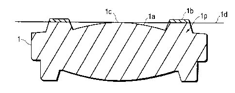
Figs. 3A through 5. In Figs. 3A, 3B and 3C, the upper side of the lens is
opposed to the
back side of the disc. In Fig. 3A, a protective member lb separate from a lens
main body la
is attached to a peripheral flat surface portion of the lens main body la of
an objective lens 1
opposed to the back side of the disc.
This protective member lb is formed as a ring surrounding the lens main body
la
and is high enough so as to protrude beyond a plane 1 d which is tangent to
the apex of the
convex surface lc of the lens main body la.
The protective member lb is preferably formed of an elastic material having a
fixed level of hardness, such as rubber, plastic or other suitable materials.
Examples of
suitable rubber materials include: natural rubber, butyl, polyurethane
VitonT"~ and other
synthetic rubbers. Examples of suitable plastics include: nylon, Teflon,
Delrin, Torlon and
polycarbonate. Examples of other suitable materials include: cotton, paper and
other soft
materials.
In Fig. 3B, the top portion of a protective protrusion lp of the conventional
objective lens 1 is cut away, and the protective member lb is attached to the
surface of the
portion of the protective protrusion lp. The protective member lb protrudes
beyond a plane
ld which is tangent to the apex of the convex surface lc of the lens main body
la. That is,
the protective member lb is only provided on the protective protrusion lp
surrounding the
lens main body la. In one embodiment, the protective protrusion lp is
integrally formed
with the objective lens 1. The protective member lb is stacked on top of the
protective
protrusion lp. Due to the small working distance between the objective lens 1
and the disk,
it is important to minimize the height of the protective member lb above the
apex of the
convex surface 1 c of the lens main body 1 a. If the protective member lb
protrudes to a
larger degree than necessary it is liable to collide with the back surface of
the disc, which is
undesirable. That is, it is undesirable to simply stack the protective member
1 b on the
protective protrusion lp well beyond the lens main body la since the
protective member lb
would forcibly rub against the back surface of the disc. Further, the
reproduction of signals

CA 02362902 2001-08-16
WO 00/49445 PCT/US00/04327
-4-
would be hindered and the focus mechanism could be damaged since focus servo
is
constantly operating during the rotation of the disc.
Fig. 3C illustrates an embodiment of the present invention wherein the
protective
member lb is formed around the perimeter of the objective lens 1. The
protective member
lb may be molded or attached by other means including: bonding, adhesives and
melting
around the objective lens 1. Again the protective member lb protrudes beyond a
plane ld
which is tangent to the apex of the convex surface 1 c of the lens main body 1
a.
While in the examples shown in Figs. 3A 3B and 3C the protective member lb is
formed continuously around the lens main body 1 a, it is possible in other
embodiments to
provide a plurality of protective members lb at equal intervals or unequal
intervals in the
periphery of the lens main body la. In still other embodiments, the protective
protrusion lp
is a plurality of equal intervals or unequal intervals in the periphery of the
lens main body
la. The height of the stacked protective member lb and protective protrusion
lp is the same
as the previously described embodiments. Furthermore, even if collision
occurs, it is not the
protective protrusion lp but the protective member lb that collides with the
back surface of
the disc. This protective member lb may be formed by applying a protective
material to the
protective protrusion lp. Because the protective member lb is made of a soft
material,
damage to the lens 1 and disc are substantially reduced as compared with
objective lenses
not having a protective member 1 b.
Figs. 4 and 5 show playback apparatuses for a disc 100 which includes: a laser
beam source 10, an aperture, a beam splitter 12, a collimator lens 13, a
focusing lens 14, a
photodetector 15 and an objective lens 1. The laser beam source 10 can be: a
laser diode, a
semiconductor laser, or the any other suitable laser source. The beam sputter
12 separates
incident light from the laser beam source 10 and reflected light from the disc
100. The
collimator lens 13 produces a parallel beam for the objective lens 1. The
focussing lens 14
focuses light onto the photodetector 15.
The apparatus shown in Fig. 5 is similar to that shown in Fig. 4 except that
in Fig. 5,
the incident beam from the laser beam source 10 is transmitted through the
beam sputter 12
and the output beam from the disk 100 is reflected by the beam sputter 12. In
the apparatus
shown in Fig. 4 the incident beam from the laser beam source 10 is reflected
by the beam

CA 02362902 2001-08-16
WO 00/49445 PCT/US00/04327
-5-
splitter and the output beam from the disk 100 is transmitted through the beam
sputter 12.
Although not shown in Figs. 4 and 5, the objective lens 1 has a protective
member around
the periphery of the lens main body as illustrated in Figs. 3A, 3B and 3C.
While only three examples are shown in Figs. 3A, 3B and 3C, various
modifications are possible as long as the protective member 1 b protrudes
beyond a plane 1 d
tangent to the apex of the convex surface 1 c of the lens main body 1 a.
Further, the objective
lens of this embodiment is applicable to any system in which a single
objective lens is used
to read from and/or write to a plurality of kinds of discs, requiring changes
in the focal
length and working distance.
As described above, in accordance with the present invention, an objective
lens has
a protective member on its surface which protects it from colliding with the
associated disc,
whereby damage to the lens and disc is avoided.
In the foregoing, an objective lens has been described. Although the present
invention has been described with reference to specific exemplary embodiments,
it will be
evident that various modifications and changes may be made to these
embodiments without
departing from the broader spirit and scope of the invention as set forth in
the claims.
Accordingly, the specification and drawings are to be regarded in an
illustrative rather than a
restrictive sense.

Dessin représentatif
Une figure unique qui représente un dessin illustrant l'invention.
États administratifs

2024-08-01 : Dans le cadre de la transition vers les Brevets de nouvelle génération (BNG), la base de données sur les brevets canadiens (BDBC) contient désormais un Historique d'événement plus détaillé, qui reproduit le Journal des événements de notre nouvelle solution interne.

Veuillez noter que les événements débutant par « Inactive : » se réfèrent à des événements qui ne sont plus utilisés dans notre nouvelle solution interne.

Pour une meilleure compréhension de l'état de la demande ou brevet qui figure sur cette page, la rubrique Mise en garde , et les descriptions de Brevet , Historique d'événement , Taxes périodiques et Historique des paiements devraient être consultées.

Historique d'événement

Description Date
Inactive : CIB attribuée 2018-06-14
Inactive : CIB enlevée 2018-06-14
Inactive : CIB en 1re position 2018-06-14
Inactive : CIB enlevée 2018-06-05
Inactive : CIB expirée 2015-01-01
Inactive : CIB enlevée 2014-12-31
Inactive : CIB expirée 2012-01-01
Inactive : CIB enlevée 2011-12-31
Inactive : CIB de MCD 2006-03-12
Demande non rétablie avant l'échéance 2004-02-18
Le délai pour l'annulation est expiré 2004-02-18
Réputée abandonnée - omission de répondre à un avis sur les taxes pour le maintien en état 2003-02-18
Inactive : Page couverture publiée 2002-01-08
Inactive : Notice - Entrée phase nat. - Pas de RE 2002-01-03
Lettre envoyée 2002-01-03
Inactive : CIB en 1re position 2002-01-03
Demande reçue - PCT 2001-12-12
Demande publiée (accessible au public) 2000-08-24

Historique d'abandonnement

Date d'abandonnement Raison Date de rétablissement
2003-02-18

Taxes périodiques

Le dernier paiement a été reçu le 2002-02-18

Avis : Si le paiement en totalité n'a pas été reçu au plus tard à la date indiquée, une taxe supplémentaire peut être imposée, soit une des taxes suivantes :

  • taxe de rétablissement ;
  • taxe pour paiement en souffrance ; ou
  • taxe additionnelle pour le renversement d'une péremption réputée.

Les taxes sur les brevets sont ajustées au 1er janvier de chaque année. Les montants ci-dessus sont les montants actuels s'ils sont reçus au plus tard le 31 décembre de l'année en cours.
Veuillez vous référer à la page web des taxes sur les brevets de l'OPIC pour voir tous les montants actuels des taxes.

Historique des taxes

Type de taxes Anniversaire Échéance Date payée
Enregistrement d'un document 2001-08-16
Taxe nationale de base - générale 2001-08-16
TM (demande, 2e anniv.) - générale 02 2002-02-18 2002-02-18
Titulaires au dossier

Les titulaires actuels et antérieures au dossier sont affichés en ordre alphabétique.

Titulaires actuels au dossier
SONY COMPUTER ENTERTAINMENT INC.
Titulaires antérieures au dossier
KAZUO MIURA
Les propriétaires antérieurs qui ne figurent pas dans la liste des « Propriétaires au dossier » apparaîtront dans d'autres documents au dossier.
Documents

Pour visionner les fichiers sélectionnés, entrer le code reCAPTCHA :


Pour visualiser une image, cliquer sur un lien dans la colonne description du document. Pour télécharger l'image (les images), cliquer l'une ou plusieurs cases à cocher dans la première colonne et ensuite cliquer sur le bouton "Télécharger sélection en format PDF (archive Zip)" ou le bouton "Télécharger sélection (en un fichier PDF fusionné)".

Liste des documents de brevet publiés et non publiés sur la BDBC .

Si vous avez des difficultés à accéder au contenu, veuillez communiquer avec le Centre de services à la clientèle au 1-866-997-1936, ou envoyer un courriel au Centre de service à la clientèle de l'OPIC.


Description du
Document 
Date
(aaaa-mm-jj) 
Nombre de pages   Taille de l'image (Ko) 
Dessin représentatif 2002-01-06 1 6
Abrégé 2001-08-15 1 39
Revendications 2001-08-15 3 86
Description 2001-08-15 5 231
Dessins 2001-08-15 6 58
Rappel de taxe de maintien due 2002-01-02 1 111
Avis d'entree dans la phase nationale 2002-01-02 1 193
Courtoisie - Certificat d'enregistrement (document(s) connexe(s)) 2002-01-02 1 113
Courtoisie - Lettre d'abandon (taxe de maintien en état) 2003-03-17 1 178
PCT 2001-08-15 7 261
Taxes 2002-02-17 1 25