Note : Les descriptions sont présentées dans la langue officielle dans laquelle elles ont été soumises.
CA 02363268 2001-11-15
"Gas injection system, particularly of methane, for
internal combustion engines, and pressure regulating
valve comprised in said system"
* * *
DESCRIPTION
The invention relates to gas injection systems,
particularly of methane, for internal combustion
engines, for the type comprising:
a plurality of electromagnetically controlled injectors
associated to the various cylinders of the engine,
a distributing manifold, or rail, communicating with
said injectors,
a reservoir feeding the distributing manifold, where
the pressurised gas is accumulated,
a pressure regulating valve interposed in the
connection between the reservoir and said distributing
manifold, and
an electronic control unit set up to control the
injectors and to control the opening time to meter the
amount of gas injected in each cylinder according to
the operating conditions of the engine.
Methane injection systems of the type indicated above
have been recently proposed to replace more traditional
systems which employ distributing devices to meter the
methane to be mixed with the air feeding the engine,
according to an arrangement which is similar to that of
a normal gasoline carburettor. These more traditional
solutions are not acceptable because they are not
suitable for working in conjunction with an engine
electronic control system which particularly is capable
of controlling metering according to the composition of
the exhaust gas detected by a lambda sensor. For this
reason, the applicant has previously proposed (see
European Patent EP 0 801 223) a methane injection
system for internal combustion engines comprising a
1
CA 02363268 2001-11-15
plurality of electromagnetically controlled injectors
which are activated by an electronic control unit in
order to meter the amount of gas injected in each
cylinder according to the operative conditions of the
engine.
In the methane electronic injection systems proposed to
date, methane metering in the engine cylinders is
obtained by varying the opening time of the injectors
according to the various operative parameters of the
engine, such as the position of the accelerator pedal,
the speed of revolution of the engine, the ambient
temperature, the altitude (which effects the amount of
air taken in by the engine), etc. The opening time of
the injectors is the only parameter which can be used
to control methane metering, because the pressure of
the methane in the distributing manifold is essentially
constant.
Furthermore, in said known systems, the pressure
regulating valve interposed between the methane
reservoir and the distributing manifold essentially
consists of a self-standing component, comprising a
restricted passage and a membrane mechanism which
regulates said passage. However, the systems configured
in such a fashion were not satisfying in transient
ratios of engine operation. Specifically, the systems
are not capable of holding pressure downstream to the
valve at a predefined value, which is essentially
constant in the case of dynamic variations in the flow
of methane, such as, for example, in the case of abrupt
engine acceleration. Moreover, the systems are capable
of working at a single predefined pressure value to be
created in the distributing manifold. In actual fact,
the engine operation presents a very high load dynamics
which originates methane load variations, also for
2
CA 02363268 2001-11-15
ratios in the range of 1:30 or 1:40. The pressure
regulating valve is usually designed on the basis of a
compromise between the existing needs in extreme
conditions of load of the engine. This is because a
pressure regulating valve with an excessively small
passage may be optimal when the engine is idling but
will not provide an adequately fast response when the
engine load increases rapidly, such as in the case of
abrupt acceleration. Conversely, if the passage of the
pressure regulating valve is relatively wide, the
system will respond well to high engine loads but will
not be capable of ensuring accurate metering at low
loads.
The object of the invention is to obviate said
shortcomings, making a system which is capable of
ensuring accurate gas metering in all conditions of
operation of the engine and particularly in the case of
rapid variations of gas flow determined by abrupt
variations of engine load.
In order to achieve this object, the system according
to the invention is characterised with respect to the
known systems principally in that in comprises means
for regulating the pressure of the gas= in the
distributing manifold.
More precisely, said regulation means comprise:
an electromagnetic actuator controlling said pressure
regulating valve,
a sensor of the pressure in the distributing manifold,
suitable for sending an electrical signal indicative of
said pressure to the electronic control unit,
a sensor of the pressure in the gas feeding line
between the reservoir and the pressure regulating
valve, suitable for sending a electrical signal
indicative of said pressure to the electronic control
unit,
3
CA 02363268 2001-11-15
memory means associated to said electronic control unit
containing maps of the theoretical predetermined
pressure values to be created in the distributing
manifold according to the variation of the parameters
of operation of the engine,
said electronic control unit being programmed to
control the electromagnetic actuator of the pressure
regulating valve according to the signals output by the
sensors of the pressure in the distributing manifold
and of the pressure in the line upstream to the
pressure regulating valve, in order to obtain a
pressure in the distributing manifold which is
essentially equal to the theoretical predetermined
value that the control unit retrieves in said memory
means according to the value of one or more parameters
of operation of the engine.
Thanks to the aforesaid characteristics, the system
according to this invention is consequently capable of
ensuring accurate metering of gas in the cylinders of
the engine in any condition of operation of the engine.
From a practical point of view, the variation of
pressure in the distributing manifold can reach, for
example, ratios in the order of 1:3 or higher, for
example with a minimum pressure value essentially equal
to 3 bars and a maximum value equal to approximately 9
bars. Thanks to the possibility of regulating the
pressure value in the distributing manifold, the system
is capable of optimally managing any static or dynamic
condition of operation of the engine.
Said pressure regulating valve according to the
invention has a valve seat and a lock pin moveable
between a closed position, in which the lock pin is in
contact with the valve seat, and an open condition, in
which a restriction is formed between the lock pin and
the valve seat putting an inlet opening communicating
4
CA 02363268 2001-11-15
with the line from the reservoir into communication
with an outlet opening communicating with the line
leading from the distributing manifold. An important
characteristic of the invention is in that said control
unit is set up to control a periodical switching of the
pressure regulating valve between said closed and open
conditions, at a predefined frequency. In other words,
alternatively to progressively and continuously varying
the passage of the pressure regulating valve according
to the electrical control signal sent hereto, the
regulation of the pressure in the distributing manifold
can also be obtained by opening and closing the valve
at a constant frequency. In this case, the regulation
of the valve is obtained by varying the duty cycle of
the valve, i.e. by varying the ratio between opening
time and total period in each opening and closing cycle
of the valve according to the pressure upstream and
downstream to the valve and according to the conditions
of operation of the engine, and particularly to the
conditions of static and dynamic load of the engine.
According to an additional characteristic of the
invention, said predefined frequency is chosen
essentially equal to the frequency at which any
injector in the system is activated. The opening of the
pressure regulating valve is synchronous and timed in
advance with respect to the activation of the
injectors, so that said valve opens before each
activation of any injection in the system. In this way,
the pressure regulating valve also acts as a pre-
metering valve, thus performing an important pre-
metering function of the fuel immediately before it is
injected into the cylinders of the engine via the
respective injector.
Thanks to the method described above for regulating the
pressure, a valve with a relatively high cross-
CA 02363268 2001-11-15
sectional passage can be used, ensuring in any case
precision and promptness of operation in any condition
of operation. Furthermore, the choppered control of the
pressure regulating valve described above ensures a
more robust system for controlling the pressure in the
distributing manifold deriving from the capacity of
pre-metering the fuel, as mentioned above, before it is
injected into the cylinders of the engine.
Additionally, said electronic control unit can be set
up to implement said choppered regulation, i.e. by
varying the duty cycle of the valve only when the speed
of revolution of the engine is under a predetermined
value, while for higher engine speeds the control unit
is set up to cause a progressive opening of the valve
according to the conditions of operation of the engine.
An additional advantage of the system according to the
invention is that the system is capable of ensuring
full operativeness at very low values of the pressure
in the methane reservoir 5, i.e. also when the
reservoir is nearly entirely empty, this obviously
increases the range of the motor vehicle. In this case,
the driver may be alerted since when the reservoir is
nearly empty the engine performance that can be ensured
will obviously be reduced.
Regardless of the injection system described above, the
invention also relates to a pressure regulating valve
per se, usable in gas injection system of the type
comprising a plurality of electromagnetically
controlled injectors associated to the various
cylinders in the engine, a distributing manifold of the
gas to the injectors and a feeding reservoir of the gas
to the distributing manifold, where the pressurised gas
is accumulated. Said pressure regulating valve
comprises, according per se to prior art, a valve body,
defining a valve seat, a lock pin moveable between a
6
CA 02363268 2001-11-15
closed position, in which the lock pin is in contact
with the valve seat, and an open condition, in which a
restriction is formed between the lock pin and the
valve seat putting an inlet opening of the valve seat
intended to communicate with a line from the reservoir
into communication with an outlet opening communicating
with a line leading from the distributing manifold of
gas to the injectors, first elastic means for pushing
the lock pin towards its closed position and solenoid
means for moving the lock pin towards its open position
whereby contrasting the action of said first elastic
means.
The invention relates to a valve of the type described
above, characterised in that said lock pin comprises a
stem slidingly mounted in a cylindrical cavity of the
valve body and a reduced diameter portion which defines
an annular chamber inside said cavity communicating
with said inlet opening, so that the pressure in the
line communicating with said inlet opening acts on both
end surfaces of said annular chamber and consequently
does not cause a substantial movement of the lock pin.
Always according to the invention, the valve comprises
second elastic means tending to move the 'lock pin
towards its open position, said second elastic means
having a load lower than that of said first elastic
means. The lock pin according to the invention is
consequently of the balanced type. An additional
characteristic of this invention is in that said stem
has a first end facing said solenoid means and a second
end defining an auxiliary chamber inside said
cylindrical cavity, said auxiliary chamber being in
communication with said outlet opening through the
passage in the lock pin body. Thanks to this
characteristic, the gas which may leak through the
clearance between the stem of the lock pin and the
7
CA 02363268 2001-11-15
aforesaid auxiliary cavity does not exert a force on
the lock pin, because discharged in the outlet opening
of the valve through said passage in the lock pin body.
In a preferred embodiment, the aforesaid lock pin
presents an active conical portion co-operating with a
valve seat defined by the circular edge of an end
opening of said cylindrical cavity. Said solenoid means
comprise an electrical winding connected to the valve
body and a ferromagnetic material core slidingly
mounted in the valve body, with a first end pushed by
said first elastic means and a second end which is held
in contact with said lock pin in all phases of
operation of the valve, by effect of the first and
second elastic means.
The pressure regulating valve according to the
invention is thus capable of ensuring optimal operation
of the system in any condition of operation of the
engine. The pressure regulating valve is capable of
ensuring gas pressure in the reservoir in the order of
200 bars, gas flows in the order of 40 kg/h with
moderate losses of load, not exceeding 10 bars, and is
particularly capable of fast response with switching
time between the open conditions and the closed
condition in the order of hundreds of microseconds (for
example, 500 microseconds). This advantage is obtained
because, for the aforesaid reasons, the pressure
communicated through the inlet opening of the valve
does not exert a force on the lock pin, therefore said
first elastic means which maintain the lock pin in the
normally closed condition can be relatively weak and
control the rapid opening and closing of the lock pin
with a relatively small, low-power solenoid, which is
consequently not very inductive and fast.
Additional characteristics and advantages of the
invention will now be described, by the way of example
8
CA 02363268 2001-11-15
only, with reference to the accompanying drawings
wherein:
figure 1 is a schematic view of a methane electronic
injection system for an internal combustion engine
according to the invention,
figure 2 is a cross-sectional view of an example of
embodiment of the pressure regulating valve according
to the invention,
figure 3 is a schematic view on a larger scale of a
part in figure 2 and figure 4 illustrating the
operating cycle of the valve in figure 2.
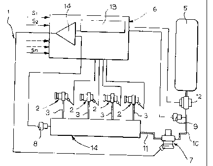
With reference to figure 1, numeral 1 generically
indicates a methane electronic injection system for an
internal combustion engine. The system comprises a
plurality of electromagnetically controlled injectors
(or injection valves) 2 associated to the various
cylinders in the engine. The assembly details of the
injectors 2 are neither described nor illustrated
herein, because the injectors can be made in any way
according to prior art and because the details are not
included in the object of the invention. The injectors
2 receive the methane via the respective lines 3 from a
distributing manifold, or rail, 4. The distributing
manifold 4 receives in turn the methane from a
reservoir 5 where the high pressure methane is
accumulated (e.g. at a pressure in the order of 200
bars). The control solenoids of the injectors 2 are
controlled by an electronic control unit 6 on the basis
of the signals S1, S21 ..., Sn, indicative of the various
parameters of operation of the engine, including the
position of the accelerator pedal, the speed of
revolution of the engine, the ambient temperature, the
altitude, etc. A pressure regulating valve 7, which is
also controlled by the control unit 6, is interposed in
the connection between the reservoir 5 and the
9
CA 02363268 2001-11-15
distributing manifold 7. The control unit 6 also
receives the signals output by the pressure sensors 8,
9 indicative of the pressure existing in the
distributing manifold 4 and in the line 10 connecting
the reservoir 5 to the pressure regulating valve 7,
respectively. The latter reduces the pressure of the
gas to the existing value in the reservoir 5 to the
value existing in the manifold 4, which is connected to
the valve 7 via the line 11. Furthermore, the system
comprises a safety valve 12, also controlled by the
control unit, for fully cutting off the outlet of the
reservoir 5.
As illustrated above, memory means 13 are associated to
the electronic control unit 6 containing theoretical
predetermined values of the pressure to be obtained in
the distributing manifold 4 as the parameter of
operation of the engine change. During the operation of
the engine, the pressure regulating valve 7, which is
electromagnetically controlled, is controlled by the
output of an error amplifier 14 on the basis of the
comparison between the pressure signal detected by the
sensor 8 in the distributing manifold 4 and the
theoretical value of the pressure in the manifold 4
which is retrieved from the memory means 13 on the
basis of the conditions of operation of the engine and
the pressures detected by the sensors 8 and 9. As
comprehensively described above, the control of the
pressure regulating valve 7 is of the choppered type.
In other words, the valve 7 is continuously switched
between the all open condition according to a cycle of
the type illustrated in figure 4, where P indicates the
total period of each opening and closing cycle of the
valve and A is the opening time of the valve in each
cycle. The regulation is obtained by varying the duty
cycle, i.e. the cycle of operation of the valve, i.e.
CA 02363268 2001-11-15
the A/P ratio between the opening time of the valve in
each cycle and the total time of the cycle. In this
way, a variation of the pressure in the distributing
manifold 4 can be obtained also in the order of 1:3 or
1:4, e.g. with a minimum of 3 bars and a maximum of 9
bars, which permits an optimal management of the system
in any static or dynamic condition of operation of the
engine, while ensuring a high level of robustness of
the system itself. Particularly, accurate operation of
the methane injection system can be ensured also in the
case of high, abrupt variations of gas flow, according
to ratios in the order of 1:30 or 1:40.
As also indicated in the preamble of the description,
the switching between the open status and the closed
status of the pressure regulating valve 7 is made at a
fixed, predetermined frequency, preferably equal to the
frequency at which any injector is activated during
operation of the engine. The opening of the pressure
regulating valve 7 is synchronous and timed in advance
with respect to the activation of the injectors 2,
therefore the valve 7 opens whenever an injector 2 is
activated, shortly before the opening of the injector.
In this way, the valve 7 also pre-meters the fuel which
is injected in the cylinders of the engine via the
respective injector.
Said choppered regulation of the valve can also be made
only under a predetermined speed of revolution of the
engine, while over this value the electronic control
unit continuously and progressively opens the valve
according to the conditions of operation of the engine.
Figure 2 illustrates a preferred embodiment of
implementation of the valve according to the invention.
The valve, generically indicated with numeral 7,
comprises a valve body 15 in which a cylindrical cavity
16 is defined. The cavity 16 has an end opening 17
11
CA 02363268 2001-11-15
whose annular edge defines a valve seat for a lock pin
18 with an active part shaped as a frustum of a cone
and a cylindrical stem 19 slidingly mounted in the
cylindrical cavity 16. The lock pin 18 is held in the
closed condition, in contact with the valve seat 17, by
a spring 30 mounted in the body 15 of the valve which
presses against the lock pin 18 by interposition of a
ferromagnetic core 20 associated to a solenoid W which
is also mounted in the body of the valve 15. The core
20 comprises a cylindrical stem 21 joined to an end of
a plate 22 facing one end of the solenoid W. The
opposite end of the stem 21 of the core 20 rests on an
end of the lock pin 18. The opposite end of the lock
pin 18 is pushed by a spring 23 whose load is lower
than that of the spring 30.
As clearly appears in figure 3, the stem 19 presents a
reduced diameter part 24, which defines an annular
chamber 25 communicating via the passage 26 with an
inlet opening 27 of the valve intended to be connected
to the line 10 from the pressurised gas reservoir 5. By
effect of this arrangement, the pressure of the gas in
the reservoir, communicated to the chamber 25, is sent
to both end surfaces 25a, 25b of the chamber 25 and
therefore does not cause any substantial movement of
the lock pin 18. Consequently, the load of the spring
30 required to ensure the closed condition of the lock
pin when the system is not active is relatively low.
The spring 23 is required to ensure that the lock pin
18 is always kept in contact with the ferromagnetic
core 20 of the solenoid. Consequently, it is sufficient
for the spring 30 to have a load slightly higher than
that of the spring 23 to ensure the closure of the lock
pin 18 in the inoperative condition of the system. For
the same reason, the solenoid W is capable of ensuring
a very rapid opening of the lock pin without requiring
12
CA 02363268 2001-11-15
a high supply power because it simply needs to overcome
the different of loads between the spring 30 and the
spring 23.
Since the clearance existing between the stem 19 and
the cylindrical cavity 16 can determine a leakage of
methane into the chamber 25 of the chamber 28 located
under the stem 19 (with reference to figure 3), the
body of the lock pin presents an internal passage 29
which puts the chamber 28 directly into communication
with the outlet opening 31, connected to the line 11
which leads to the distributing manifold 4. In the way,
the pressure in the chamber 28 is equal to that at
valve output and does not consequently determine the
application of any force of the lock pin.
In operation, as previously indicated, the electronic
control unit intermittently activates the solenoid so
to continuously switch the lock pin between its closed
position and its open position, the regulation being
obtained by intervening on the duty cycle, i.e. on the
operating cycle of the valve, i.e. of the A/P ratio
defined above, with the advantages indicated above.
An additional important advantage of the system
according to the invention is that the system is
capable of ensuring full operativeness also at very low
pressure values in the methane reservoir 5, i.e. also
when the reservoir is nearly entirely empty, which
obviously increases the range of the motor vehicle.
Moreover, numerous changes can be implemented to the
construction and embodiments of the invention herein
envisaged without departing from the scope of the
present invention, as defined by the following claims.
13