Note : Les descriptions sont présentées dans la langue officielle dans laquelle elles ont été soumises.
CA 02363775 2001-11-26
A SYMMETRIC, HIGH VERTICAL FIELD OF VIEW 360 DEGREE
REFLECTOR USING CUBIC TRANSFORMATIONS AND METHOD
The present invention relates to a panoramic imaging apparatus and more
particularly to an apparatus and method for capturing a 360 degree panoramic
image
of a scene using a single, stationary camera, for use in a virtual reality
display
system or to produce panoramic photographs.
BACKGROUND OF THE INVENTION
Virtual reality (VR) is becoming more and more popular and is a much
desired new media entertainment and display concept. From video games that
attempt to re-create the sense of live three-dimensional action, to Hollywood
movies,
to Web site displays that seek to put the viewer into the scene, virtual
reality is in
demand. People have a desire to experience the world from a realistic
perspective
that makes them feel like they are right in the action, and not just observing
a flat
two-dimensional picture from a single fixed vantage point.
In approximately 1995, AppleTM Computer released a computer program
called QuicktimeTM VR that allowed the navigation of a panoramic photograph on
a
computer screen by moving the computer mouse. One of the advantages of this
general approach is that it is photo-realistic, while at the same time having
very small
file sizes that are easy to handle and are well suited for transfer from one
computer
to another. The navigation capabilities provide one with the sense of moving
around
in a three-dimensional space, as if one was actually present in the scene.
Since that
time, many other companies have released similar virtual reality display
systems that
can be used to view and navigate a panoramic photograph. These programs are
now widely available and many of them are available free of charge.
Virtual reality display systems such as QuicktimeTM VR require systems for
quickly and inexpensively capturing high quality, 360 degree, panoramic
images.
One of the difficulties in capturing the required panoramic image is that most
currently existing photographic systems operate with a limited field of view
and are
unable to capture an entire 360 degree panoramic view of a scene. A standard
-1-
CA 02363775 2001-11-26
camera lens is only able to look outward at considerably less than 180
degrees.
Even with so-called "fish-eye" lenses, the field of view is at most 180
degrees. Such
systems are therefore unable to capture, in a single shot, a 360 degree view
of a
scene required for virtual reality viewing.
Over the past century, panoramic photography has used a wide variety of
image capture techniques. All of these methods suffer from the disadvantages
of
being slow, inefficient and costly. The traditional approach to the problem is
to take a
number of pictures of a scene in a 360 degree panorama and carefully stitch
them
together. At one time, these separate images were merely mounted side-by-side
on
a cardboard backing, but now they can be scanned, converted to computer
readable
formats and combined using "stitching" programs. The resulting panoramic image
is
then converted to a format that can be displayed as a navigable virtual
reality scene
using a display program such as QuicktimeTM VR. Of course, taking multiple
photographs is costly and time consuming, and the scanning and stitching
process
tends to introduce artifacts into the final image. Furthermore, when separate
images
are stitched together, they tend to be uneven, requiring substantial cropping
of the
top and bottom of the scene.
Other panoramic image capturing techniques known in the art include: swing
lens cameras that take images by swinging the lens during the exposure;
rotational
panoramic cameras that revolve on a tripod while the film moves in the
opposite
direction; and strip-scan panoramas, like those used to capture horses at a
finish
line, that expose the image of a moving object onto a piece of film moving at
the
same speed. All of these techniques are generally unacceptable for producing
images for use in current virtual reality displays.
Some recent attempts have been made to address this problem by using only
two photographs of the same scene taken in exactly opposite directions with a
single
fish-eye lens. However, the two photographs must still be carefully aligned
and
stitched together to produce the required 360 degree panoramic view. Again,
the
stitching process is slow and introduces artifacts into the final image.
Moreover, any
changes in lighting or object positioning within the scene between the two
shots will
cause disruption of the final image. A further disadvantage of using a fish-
eye lens is
-2-
CA 02363775 2001-11-26
that it can introduce considerable radial distortion. That is, horizontal
lines of an
object near the top of a scene appear as curved rather than straight lines.
Another solution has been described in Canadian Patent Application No.
2,174,157 (Nalwa) which describes a four-sided, pyramid shaped reflective
element
to reflect images from four different directions to four different cameras
having a
common optical centre. The resulting images must also be stitched together
electronically to form a continuous 360 degree view. One of the problems with
this
solution is that it requires multiple cameras which must be carefully aligned
to ensure
that each has the same optical centre. A further disadvantage is that the
angle of the
flat mirrors must be carefully aligned and maintained.
It is clear from the above that the techniques, skills and costs associated
with
obtaining 360 degree panoramic images suitable for virtual reality display
applications could be significantly improved with the availability of
innovative
panoramic imaging devices and methods.
BRIEF SUMMARY OF THE INVENTION
The object of the present invention is to overcome the above shortcomings by
providing a new and improved apparatus and method for rapidly obtaining high
quality, inexpensive 360 degree panoramic images of a scene, using a single
image
obtained from a single stationary camera.
A further object of the present invention is to provide an apparatus and
method of obtaining 360 degree panoramic images of a scene which, when
converted to a format for display using virtual reality display software, are
small in
size and easy to manipulate.
Another object of the present invention is to provide a light weight, portable
imaging apparatus for capturing 360 degree panoramic images of a scene.
Briefly, these objectives are achieved by the present invention, which
provides a mirror in the shape of an inverted dome, having an outward facing
generally smooth convexly shaped peripheral surface to reflect light emanating
from
-3-
CA 02363775 2009-03-09
a 360 degree panoramic scene to be recorded by a suitable camera, which may
preferably be a still or video camera having a digital sensor such as a charge
coupled device (CCD) sensor or a complementary metal oxide semiconductor
(CMOS) sensor, but which may also be a conventional film based camera. In a
preferred embodiment, the inverted, dome-like convex mirror is mounted on a
mast
secured at one end through the central axis of the mirror and at the other end
to the
centre of a flat glass plate located on a horizontal plane perpendicular to
the mast.
The flat glass plate is mounted in a suitable structure above a flat mirror
placed at a
45 degree angle to the flat glass plate so as to reflect light reflected
downward from
the mirror, 90 degrees towards a camera whose optical axis is perpendicular to
the
axis of the mast. In an alternative preferred embodiment, the inverted dome-
like
convex mirror is mounted directly above and coincident with the optical axis
of the
camera without requirement for a flat mirror to redirect the light by 90
degrees. In
both cases, the inverted, dome-like convex mirror has a profile that projects
a 360
degree view of the environment in which it is mounted onto the imaging plane
of the
camera.
The inverted, dome-like convex mirror projects a warped 360 degree image
of the scene onto the image plane of the camera which records the image.
Knowledge of the geometric definition of the mirror allows to transform a high
quality
360 degree panoramic image of the original scene which can be displayed on a
monitor or printed as a single flat image. The resulting de-warped image can
also be
formatted for display as a navigable three-dimensional image on a computer
monitor
using any widely available virtual reality display program, such as
QuicktimeTM VR for
example.
In accordance with the objectives of the present invention there is provided a
panoramic imaging apparatus for viewing a scene comprising: an inverted dome-
like
mirror having an outward facing convexly shaped peripheral surface, for
reflecting a
360 degree panoramic view of the scene toward a single viewing location.
In a broad aspect, then, the present invention relates to a panoramic imaging
apparatus for capturing panoramic images of a scene, the panoramic imaging
apparatus comprising: a dome-like convex mirror, the convex mirror reflecting
the
panoramic images from 360 degrees around the mirror; an image capture
mechanism, the image capture mechanism capturing the reflected panoramic
-4-
CA 02363775 2009-03-09
images; wherein the convex mirror is shaped such as to be defined by a cubic
equation, the cubic equation selected such that the reflected panoramic images
of
the scene are symmetric above and below zero degrees elevation.
In another aspect, there is provided a panoramic imaging apparatus for
capturing panoramic images of a scene, the panoramic imaging apparatus
comprising: a dome-like convex mirror, the convex mirror reflecting the
panoramic
images from 360 degrees around the mirror; an image capture mechanism, the
image capture mechanism capturing the reflected panoramic images; wherein the
convex mirror is shaped such as to be defined by a cubic equation, the cubic
equation selected such that equal changes in elevation in the scene are
reflected to
equal changes in radius of the reflected panoramic images.
In accordance. with the further objectives of the present invention there is
provided a method of recording a 360 degree panoramic image of a scene
comprising the steps of: locating a dome-like mirror having an outward facing
convexly shaped peripheral surface within the scene so that the mirror
reflects the
360 degree panoramic image of the scene, the convex mirror being shaped such
as
to be defined by a cubic equation, the cubic equation selected such that the
reflected
panoramic image is symmetric above and below zero degrees elevation; and
sensing and recording the reflected panoramic image.
In another broad aspect, the present invention relates to a method of
presenting panoramic images, the method comprising the steps of: recording a
warped representation of a panorama; storing the warped representation as a
digitized representation; geometrically transforming the digitized
representation of
the panorama using a cubic function, the cubic function selected to correspond
with
a cubic equation used to record the warped representation; and displaying a
resulting projection of the panorama.
In another aspect, there is provided a method of presenting panoramic
images, the method comprising the steps of: recording a warped representation
of a
panorama; storing the warped representation as a digitized representation;
geometrically transforming the digitized representation of the panorama using
a
geometric function, the geometric function selected to correspond with a
geometric
-5-
CA 02363775 2009-03-09
equation used to record the warped representation; and displaying a resulting
projection of the panorama by running a QuicktimeTM VR program.
In yet another aspect, there is provided a method of recording a 360 degree
panoramic image of a scene comprising the steps of: locating a dome-like
mirror
having an outward facing convexly shaped peripheral surface within the scene
so
that the mirror reflects the 360 degree panoramic image of the scene, the
convex
mirror being shaped such as to be defined by a cubic equation, the cubic
equation
selected such that equal changes in elevation in the scene are reflected to
equal
changes in radius of the reflected panoramic image; and sensing and recording
the
reflected panoramic image.
The present invention advantageously provides for the rapid acquisition of
high quality, professional grade 360 degree panoramic images at a much lower
cost
than professional grade optics. Yet another advantage is that the dome-like
mirror
and supporting apparatus can be made of plastic, further reducing costs and
increasing portability. It is a unique single-surface mirror with a chrome-
like bonded
surface. A further advantage is that the present invention requires only a
single
camera and a single photograph to reproduce a 360 degree panoramic view of a
scene. There is no requirement for multiple cameras or stitching together of
multiple
photographs. Another advantage is that the file sizes of the de-warped images
produced by the present invention are much smaller than those typical of
video.
Therefore, when being viewed as a navigable three-dimensional image in a
virtual
reality display program such as QuicktimeTM, the images transfer much quicker
and
activate much faster.
Further objects and advantages of the present invention will be apparent from
the following description, wherein preferred embodiments of the invention are
clearly
shown.
BRIEF DESCRIPTION OF THE DRAWINGS
The present invention will be further understood from the following
description with reference to the drawings in which:
-5a-
CA 02363775 2001-11-26
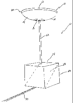
Figure 1 is a perspective view of a preferred embodiment of the present
invention.
Figure 2 is a cross-sectional view of a preferred embodiment of the present
invention showing an attached camera used for recording images.
Figure 3 is a plan view of a typical warped image of the simulated room
shown in Figure 6 and projected on the image plane of a camera by the present
invention.
Figure 4 is a cross-sectional view of the inverted dome-like convex mirror of
the present invention.
Figure 5 is a graph showing the cross sectional surface curvature of a typical
inverted dome-like convex mirror of the present invention.
Figure 6 is perspective view of a simulation showing a convex dome-like
mirror of the present invention suspended in a simulated room.
Figure 7 is a schematic side plan view of an alternative embodiment of the
present invention in which the dome-like mirror is attached directly to the
camera.
Figure 8 is a schematic side plan view of an embodiment of the present
invention which includes two convex dome-like mirrors used to image a
substantially
spherical view.
Figure 9 is a cross-sectional view of a further preferred embodiment of the
present invention showing an alternative arrangement of the present invention
collapsed for shipping purposes.
Figure 10 is a flow chart showing an embodiment of a method of the present
invention for acquiring and processing panoramic images.
DETAILED DESCRIPTION OF THE
PREFERRED EMBODIMENTS OF THE INVENTION
Referring to Figure 1, a preferred arrangement of the present imaging
apparatus 10 is shown which comprises an inverted dome-like mirror 12 having
an
outward facing convexly shaped peripheral surface 14. Dome-like mirror 12, as
also
shown in isolated cross-section in Figure 4, has a horizontal flat base 16, a
horizontal
flat top 18 and a vertical edge 20. Vertical edge 20 is added to the preferred
arrangement shown for the purpose of increasing the strength of the mirror,
but is not
a required feature of the present invention. Dome-like mirror 12 uses complex
geometry rather than a polar rectangular transformation. The convex shape of
the
-6-
CA 02363775 2001-11-26
invention has been specifically designed to produce poor quality images, in
which
straight lines look bent and objects appear distorted, when a transformation
from
polar coordinates to rectangular coordinates is used. This is the most common
geometric fit used with either concave or convex mirrors. The mirror of the
present
invention goes beyond this in defining a shape that is more sophisticated
therefore
making it more difficult to find a fit that matches the shape for dewarping
purposes.
The shape of the mirror 12 is defined by a cubic equation. It is also key to
compensate in the shape definition for the smaller central than outer
circumference
on the mirror 12. Since there is more surface area on the outer rim of the
mirror 12,
there tends to be more pixels there and better resulting resolution in that
area of the
reflection. In order to compensate, the inner mirror slope of the present
invention
accounts for this situation in that bands on the inner circumference are
approximately
2.3 times taller than around the outer rim. Using geometric projections based
on a
cubic function also allows for a very wide vertical field of view with
versions at 45
degrees viewing up and 45 down, for a total vertical field of view of 90
degrees, and
52 degrees up and down, for a total of 104 degrees, and 60 degrees up and down
for
a wide angle vertical view of 120 degrees up and down. Said mirror 12 also
allows
for symmetry, with the same number of degrees above and below the horizon. It
is
further designed to balance the number of pixels or light rays coming in from
above
and below the horizon. The shape is also designed to minimize the blindspot in
the
centre of the mirror.
Dome-like mirror 12 is supported in an inverted position by mast 22 attached
at one end through the centre of mirror top 18 and at the other end to a flat
transparent plate 24, preferably made of either glass or plastic, positioned
on a
horizontal plane perpendicular to mast 22. Flat transparent plate 24 is
supported in a
suitable structure such as a glass or plastic support cube 26 or tube,
however, it will
be appreciated by one skilled in the art that any suitable supporting
structure would
function equally well in the present arrangement for supporting dome-like
mirror 12.
In the illustrated embodiment of the invention, a flat mirror 28 is located in
the
structure below flat transparent plate 24 and is positioned at an angle of 45
degrees
to flat transparent plate 24. To assist in the alignment of the image
reflected from
dome-like mirror 12, the angle of flat mirror 28 in relation to flat
transparent plate 24
can be made adjustable using an adjustment screw 29 (see Figure 2) located at
the
-7-
CA 02363775 2001-11-26
base of flat mirror 28. Imaging apparatus 10 includes a track 30 attached to
the base
of support cube 26 and extending at an angle of 90 degrees to mast 22.
As shown in Figure 2, track 30 supports a camera 35 (the image capture
mechanism) which is removably attached to track 30 and located so that its
optical
axis is perpendicular to mast 22 and most, if not all, the curved surface 14
of dome-
like mirror 12 is within the field of view of the camera. Camera 35 can be any
suitable imaging device such as a film based still camera, a movie camera, or
a still
camera or video camera having a digital image sensor such as charged coupled
device (CCD) sensor or a complementary metal oxide semiconductor (CMOS)
sensor. Camera 35 is movable along track 30, allowing it to be located either
closer
to or farther away from flat mirror 28, permitting adjustment of the image
size and
location on an image plane 42. A zoom in camera would serve the same function.
Further, it should be noted that the software used in combination with the
present
invention allows for the resulting image to be flipped depending on which
device
might be used.
Figure 3 shows a warped circular image 40 of the outward environment as
shown in Figure 6 and projected onto image plane 42 of camera 35 by the
arrangement of the present invention shown in Figures 1 and 2. The warped
circular
image 40 represents 360 degrees in azimuth of the viewed environment and from
approximately -90 degrees (that is vertically downwards in the arrangement
shown in
Figure 2) to greater than 0 degrees (horizontal) in elevation. In practice,
the lowest
elevation is determined by the size of flat top 18 of dome-like mirror 12
which blocks
the downward view of the mirror at the lowest elevations. The highest
elevation is
determined by the curvature of the convex surface of the dome-like mirror 12
or its
cross-sectional profile as shown in Figure 5, and generally extends equally
far above
the horizon so that objects above 0 degrees elevation, in the range of 45, 52
or 60
degrees elevation, are visible.
In the warped circular image 40 generated by the dome-like mirror 12, a given
radial direction corresponds to a specific azimuth in the environment, and
since the
warped image produced by the dome-like mirror 12 is inverted, increasing radii
correspond to increasing elevations. Thus, in the warped image 40 shown in
Figure 3, the outer portion of the circle corresponds to the ceiling or top of
the
-8-
CA 02363775 2001-11-26
environment shown in Figure 6, while the inner edges of the circle correspond
to the
bottom or floor.
The convex surface profile of dome-like mirror 12 may be any one of a large
number of practical profiles, but in the case of the preferred arrangement of
the
present invention described herein, the convex profile of dome-like mirror 12
is
preferably chosen to map equal changes in elevation in the scene to equal
changes
in radius in the warped image. This ensures that both the top and bottom of
the
scene receive an equal number of image pixels, thus preventing stretching or
distortion of image lines which is a common problem for imaging systems using
convex mirrors.
As shown in Figures 1, 2 and 4, inverted dome-like mirror 12 has a flat base
16, and a small flat top 18, which is created by slicing the top off. In one
preferred
embodiment of the present invention, base 16 has a radius of approximately 1.6
inches and top 18 has a radius of approximately one-quarter inch.
The profile of dome-like mirror 12 was chosen by conducting extensive
simulations based on geometric projections. The convex curvature of surface 14
was varied and different sections were selected, until the ideal combination
was
obtained which, when inverted, projected a symmetric view above and below the
horizon with more surface area or central concentric circles, high vertical
field of
view, while using a cubic geometric function, resulting in a distorted image
if a polar
rectangular transformation was used. One preferred curvature for the surface
14 of
dome-like mirror 12 is shown in Figure 5.
The various dimensions of the present invention as shown in Figure 2, will
vary depending on the type of camera 35 used and the exact positioning and
curvature of the dome-like mirror 12. In one typical arrangement, the
applicant has
attached a NikonTM digital camera to track 30. In this preferred arrangement,
the
Nikon TM camera is located three-quarters of an inch from the base of mirror
28 which
is set at a 45 degree angle within support structure 26 which measures four
inches
long, two and one-half inches wide and two and four-tenths inches high. The
base 16 of dome-like mirror 12 is four inches in diameter and the top 18 is
one and
-9-
CA 02363775 2001-11-26
one-half inches in diameter, and the dome-like mirror 12 is supported on mast
22
approximately five and one-quarter inches above the surface of transparent
plate 24.
It is important to select the diameter of top 18 so as to prevent imaging of
objects directly below the dome-like mirror, such as camera 35 or support 26.
This
permits placement of the camera much closer to the dome-like mirror 12.
Placement
of the camera closer to the dome-like mirror 12 helps to eliminate vibration
and
improves the portability of the system.
As shown in Figures 1 and 2, it is important that during operation mast 22 not
extend through the flat transparent plate 24 by any significant amount. Any
extension of mast 22 into the optical field of view of camera 35 will result
in an image
of mast 22 appearing on the image plane of the camera. If mast 22 is merely
imbedded in transparent plate 24, or securely screwed in, the entire mast is
obscured
by the blind spot created by top 18 of dome-like mirror 12, which appears as a
small
dark circle in the centre of the circular warped image 40. On the other hand,
the
extension tube moves the end of the mast away from the camera, to make the
blindspot look smaller.
However, referring to Figure 9, in order to reduce the size of the arrangement
of the present invention shown in Figures 1 and 2, during shipment or storage,
mirror
28 can be provided with a central hole 50 located directly inline with mast
22. Mast
22 can be constructed so as to be slidably secured within transparent plate 24
thereby permitting mast 22 to be lowered through hole 50 reducing the size of
the
present invention for shipping or storage. Hole 50 is obscured by the blind
spot of
the apparatus created by the size of top 18 and is thus not visible on the
image plane
42.
The positioning of flat mirror 28 at a 45 degree diagonal is a further
important
aspect of the preferred embodiment of the invention shown in Figures 1 and 2.
A
similar arrangement has been used in telescopes to reflect light gathered from
a
large primary mirror and direct it at an angle of 90 degrees to the optical
axis of the
primary mirror for focussing and viewing. The arrangement is referred to as a
"Newtonian Reflector" and, as used in the present invention shown in Figures 1
and
2, permits camera 35 to be placed at a 90 degree angle to the optical axis of
dome-
-10-
CA 02363775 2001-11-26
than upwards vertically toward the dome-like mirror. The arrangement also
permits
the use of almost any type of camera so long as it can be mounted on track 30
and
does not limit the invention to cameras which can be mounted directly to the
dome-
like mirror 12.
In an alternative embodiment of the present invention, as shown in Figure 7,
camera 35 is mounted on mast 22 or more conveniently through an adapter tube
to
fit the camera directly in line with dome-like mirror 12 so that the optical
axis of
camera 35 coincides with the optical axis of dome-like mirror 12. In this
alternative
arrangement, the 360 degree panoramic image of the environment reflected from
the
dome-like mirror 12 is projected directly onto the image plane 42 of camera
35, thus
eliminating the requirement for flat mirror 28. One advantage of the
arrangement
shown in Figure 7 is that the entire apparatus can be made smaller and lighter
and is
thus more portable.
As mentioned above, and as shown by example in Figure 3, the circular
image 40 produced on image plane 42 of camera 35 by the present invention is
usually a warped version of the viewed environment in which the azimuth
corresponds to the environmental azimuth and the radial distance corresponds
to the
elevation angle.
To interpret this warped image and to produce an image that is usable in a
virtual reality viewer such as QuicktimeTM VR, the warped image must be de-
warped
using a suitably programmed computer or microprocessor to transform pixels in
the
warped image to rectilinear coordinates.
In an alternative embodiment of the present invention, ridges or similar
aberrations may be positioned, in ring-like fashion around the dome-like
mirror 12, in
close proximity to flat top 18. This will result in making unwarping more
difficult and
can be seen as an added security feature.
Finally, the resulting de-warped image can be printed or displayed as a
panoramic photograph or further processed and formatted for display using any
virtual reality viewer such as QuicktimeTM VR. Alternatively, the electronic
signal
generated by a camera having a CCD or CMOS sensor at its imaging plane can be
-11-
CA 02363775 2001-11-26
de-warped directly in the camera or in a set top box, thus producing a de-
warped
image formatted for display on a monitor or in a virtual reality viewer. If
the camera
used is a video camera and the computer used has sufficient processing power
and
transmission bandwidth, it is within the concept of the present invention that
successive images can be captured, processed and actively displayed to create
a
live, full-motion, three dimensional navigable display of the viewed
environment.
In practice, the present invention is extremely simple to use. For many
applications the most advantageous panoramic view of a scene is one taken from
the
perspective of a standing or seated person. Using either of the preferred
embodiments of the present invention described and shown in Figures 1 and 2 or
Figure 7, the operator, while standing or sitting, simply holds the invention
at or
slightly above eye level and activates camera 35 to record an image of the
scene.
Because of the small blind spot created by top 18 of dome-like mirror 12, both
the
operator and the camera are not recorded in the resulting panoramic image. For
more serious applications, the apparatus can be placed on a centrally located
tripod
and the camera activated remotely or by timer.
Referring to Figure 10, there is shown a flow chart illustrating a method for
acquiring and processing panoramic images in accordance with an embodiment of
the present invention. The steps include locating an inverted dome-like mirror
in the
environment to be viewed 110, reflecting a 360 degree panoramic view of the
environment from the dome-like mirror 115, and sensing and recording the
warped
image reflected therefrom 120. The method may further include de-warping the
warped images by transforming pixels in the warped image to rectilinear
coordinates
125, displaying the de-warped image on a monitor or printing the image as a
panoramic image 130, and further processing and formatting of the de-warped
image
for display using a virtual reality viewer 135, thus permitting three-
dimensional
navigation of the viewed environment.
It is contemplated that the steps of locating the mirror 110, reflecting the
scene 115 and sensing and recording the warped image 120 can be done remotely
by a person using the preferred arrangements of the present invention
discussed
above. It is further contemplated that the warped image thereby recorded can
be
submitted to a central location where the further steps of de-warping the
image 125,
-12-
CA 02363775 2001-11-26
printing a panoramic photograph 130, or processing and formatting the image
for
display using a virtual reality viewer 135 are performed. To that effect, it
is
contemplated that in a preferred embodiment of the invention, a central
control
program will include authentication software. To initiate the image capture
process,
a user must contact a central location to activate authentication software by
obtaining
an authorization number in exchange for payment of an image processing fee.
This
approach allows the applicant to make the invention available to remote users
while
at the same time maintaining the ability to collect user fees for image
processing.
Users purchase the image processing to create a virtual reality scene, not the
entire
software.
Alternatively, the user can be allowed to save an assembled demo image,
including a watermark, before authentication software is engaged and the
processing
fee is paid. This will allow a user to preview the assembled image or show it
to
clients before incurring a processing fee. Once the central location is
contacted and
the processing fee paid, the watermark is removed.
In a further preferred embodiment, it is unnecessary for the user to make
contact with the central location to obtain an authorization number each time
a final
assembled image is processed. In this embodiment of the invention,
authentication
software includes a use counter indicating an available number of uses. Each
time a
final assembled image is processed for export to a virtual reality viewer, the
use
counter subtracts one from the total available uses, until none remain. A user
can
obtain additional uses by purchasing a processing code number, which is used
by
authentication software to reset the use counter with a desired number of
uses. The
processing code number is a unique number which designates the number of
processing units purchased and specifies the individual computer on which it
can be
used. The processing code number is obtained by contacting the central
location,
requesting the desired number of uses, and providing a unique computer
identifier
number generated by authentication software. The computer identifier number is
generated by authentication software from a serial number or numbers read from
devices connected to a computer, such as the computer's mother board or hard
drive
to ensure that the requested processing uses are made available to only one
computer.
-13-
CA 02363775 2001-11-26
As shown in Figure 8, a field of view that is almost global in scope may be
obtained by using two convex dome-like mirrors 12 mounted base-to-base, and
sharing a common optical axis. The arrangement shown in Figure 8 utilizes two
identical devices as shown in Figure 7, each having convex dome-like mirror
12, a
supporting mast 22 and a camera 32 mounted so that the optical axises of the
cameras 35 are coincident with the optical axises of the dome-like mirrors 12.
One
of the main advantages of this alternative arrangement is that the resulting
images
obtained from each mirror can be combined in the final de-warped image to
produce
a navigable three-dimensional image having 360 degrees of azimuth and a range
in
elevation from almost -90 degrees vertically downward to almost +90 degrees
vertically upward. The field of view in the final three-dimensional navigable
scene is
thus greatly expanded over an arrangement using a single dome-like mirror 12.
The imaging apparatus and method of the present invention has applications
in a wide number of areas requiring panoramic photographs and interactive
panoramic displays, of which the following is a brief, but not exhaustive,
list:
virtual home tours in the real estate industry;
virtual field trips to remote locations for use by educators and in the
tourist
industry;
virtual store tours and displays for on-line retailers,
virtual displays of entertainment venues to provide virtual spectator views
from particular seat locations; and
visualization of harsh industrial environments.
The invention may be embodied in other specific forms without departing from
the spirit or essential characteristics thereof. The present embodiments are
therefore
to be considered as illustrative and not restrictive, the scope of the
invention being
indicated by the appended claims rather than by the foregoing description, and
all
changes that come within the meaning and range of equivalency of the claims
are
therefore intended to be embraced therein.
-14-