Sélection de la langue

Search

Sommaire du brevet 2364097 

Énoncé de désistement de responsabilité concernant l'information provenant de tiers

Une partie des informations de ce site Web a été fournie par des sources externes. Le gouvernement du Canada n'assume aucune responsabilité concernant la précision, l'actualité ou la fiabilité des informations fournies par les sources externes. Les utilisateurs qui désirent employer cette information devraient consulter directement la source des informations. Le contenu fourni par les sources externes n'est pas assujetti aux exigences sur les langues officielles, la protection des renseignements personnels et l'accessibilité.

Disponibilité de l'Abrégé et des Revendications

L'apparition de différences dans le texte et l'image des Revendications et de l'Abrégé dépend du moment auquel le document est publié. Les textes des Revendications et de l'Abrégé sont affichés :

  • lorsque la demande peut être examinée par le public;
  • lorsque le brevet est émis (délivrance).
(12) Demande de brevet: (11) CA 2364097
(54) Titre français: METHODE ET DISPOSITIF POUR ACCROITRE LA FORCE DE GUIDAGE DES MOTONEIGES QU'ON PEUT ORIENTER AU MOYEN D'UNE PAIRE DE SKIS A L'AVANT
(54) Titre anglais: METHOD AND DEVICE FOR INCREASING THE STEERING FORCE OF SNOW MOBILES STEERABLE BY MEANS OF A PAIR OF FRONT SKIS
Statut: Réputée abandonnée et au-delà du délai pour le rétablissement - en attente de la réponse à l’avis de communication rejetée
Données bibliographiques
(51) Classification internationale des brevets (CIB):
  • B62D 11/00 (2006.01)
  • B62B 13/08 (2006.01)
  • B62M 27/02 (2006.01)
(72) Inventeurs :
  • ROVA, JAN-ERIK (Suède)
(73) Titulaires :
  • JAN-ERIK ROVA
(71) Demandeurs :
  • JAN-ERIK ROVA (Suède)
(74) Agent: ROBIC AGENCE PI S.E.C./ROBIC IP AGENCY LP
(74) Co-agent:
(45) Délivré:
(22) Date de dépôt: 2001-11-30
(41) Mise à la disponibilité du public: 2002-06-01
Licence disponible: S.O.
Cédé au domaine public: S.O.
(25) Langue des documents déposés: Anglais

Traité de coopération en matière de brevets (PCT): Non

(30) Données de priorité de la demande:
Numéro de la demande Pays / territoire Date
0004440-4 (Suède) 2000-12-01

Abrégés

Abrégé anglais


A method and device is disclosed for increasing the steering
force of track-driven snowmobiles being steered by means of a
pair of resiliently suspended front skis. In order to obtain
this effect when steering from the central neutral position,
the vertical spacing of the curve-outer ski from the snowmo-
bile body is increased intentionally, in order to tilt said
body towards the centre of the curve and thereby transferring
more of the snowmobile weight to the inner ski and thus in-
crease the steering pressure force thereof on the surface.

Revendications

Note : Les revendications sont présentées dans la langue officielle dans laquelle elles ont été soumises.


6
Claims
1. A method for increasing the steering force of track-
driven snowmobiles being steered by means of a pair of resil-
iently suspended front skis, characterised i n
that when steering from the central neutral position the ver-
tical spacing of the curve-outer ski from the snowmobile body
is intentionally increased in order to tilt said body towards
the centre of the curve and thereby transferring more of the
snowmobile weight to the inner ski and thus increase the
steering pressure force thereof on the surface.
2. A method according to claim 1, characterised
in that the vertical spacing of the curve-inner steering ski
from the snowmobile body is reduced in negotiating curves.
3. A method according to claim 1, characterised
in that the change of the vertical spacing of the steering
skis from the snowmobile body is made successively and propor-
tionally to the motion of the steering means.
4. A device for carrying out the method according to claim 2
in order to increase the steering force in snowmobiles with a
pair of resiliently suspended front skis, character-
ised by a tilting mechanism adapted to increase the ver-
tical spacing of the curve-outer steering ski from the snowmo-
bile body.
5. A device according to claim 4, characterised
in that the tilting mechanism is adapted to reduce simultane-
ously, when needed, the vertical spacing of the curve-inner
steering ski from the snowmobile body.
6. A device according to claim 4, characterised
in that the changes of the vertical spacing of the steering

7
skis from the snowmobile body occurs automatically and succes-
sively as well as proportionally to the steering motion.
7. A device according to claim 4, characterised
in that when travelling obliquely to a sloping surface the
tilting mechanism is disengageable from the steering function
and adjustable for compensation of said surface slope.
8. A device according to claim 7, particularly in a gas-
hydraulic spring suspension of the steering skis,
characterised in that the tilting mechanism is
adapted to be actuated by gas-hydraulic pressure of the sus-
pension of the respective ski.
9. A device according to claim 7, particularly in spring
suspensions of the steering skis by means of helically coiled
pressure springs, characterised in that the
tilting mechanism is adapted to act upon the vertical position
of the mounting point of the respective spring to the snowmo-
bile body.

Description

Note : Les descriptions sont présentées dans la langue officielle dans laquelle elles ont été soumises.

CA 02364097 2001-11-30
1
METHOD AND DEVICE 80R INCREAHINGi T8E STEERING !'ORCE OF SNON
M08ILES 8'fBERABLE BY MEANS OF A BAIR OF FRONT SKI9
The present invention refers to a method and device for in-
creasing the steering force of trackdriven snow vehicles or
snowmobiles steerable by means of a pair of preferably resil-
iently suspended front skis.
In the travel with snowmobiles steered by means of a pair of
front skis through a motorcycle-like handle bar the occupant
tries to tilt the vehicle towards the centre of the curve by
means of his body weight, sometimes in standing position, in
order to improve or increase the rather poor steering effect
of the skis. This succeeds more or less effectively dependent
on several conditions such as the body weight of the occupant,
the carrying ability of the snow surface, the steering ski
pressure, the speed and most of all the width of the driving
track or mat. The propulsion of a snowmobile, namely, is pro-
vided by means of an endless driven track or mat of a width of
about 35 to 40 cm, which now tends to increase to 50 to 60 cm.
For geometrical reasons the difficulties in steering the ve-
hicle will be still greater than before since the vehicle for
instance will be much more difficult to tilt by only the body
weight.
From US patent specification No. 3,583,507 dated 1971 is known
a powered snow vehicle in which the snow contacting surfaces
and a body frame with seated passengers can tilt or bank with
respect to the terrain in order. to obtain improved stability,
maneuverability and control. In today's bigger-sized snowmo-
biles the weight of the driver constitutes only about 1/5 of
the total weight and can therefore make no essential contribu-
tion to the steering effect on the skis.

CA 02364097 2001-11-30
2
The present invention aims at suggesting a solution to those
difficulties and the inventive method is essentially distin-
guished in that when steering from the central neutral posi-
tion the vertical distance of the curve-outer steering ski
from the snowmobile body is intentionally increased in order
to tilt said body as a whole towards the inside of the curve
and thereby to transfer more of the vehicle weight onto the
inner ski and thus increase the steering pressure on the sur-
face of the same.
For carrying out said method the invention suggests a device
which is essentially distinguished by a tilting mechanism in-
tended to increase the vertical distance of the curve-outer
steering ski from the snowmobile body when negotiating curves.
By way of example the invention will be further described be-
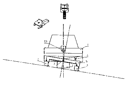
low with reference to the accompanying drawings in which Fig.
1A and B is a front view of a snowmobile, in which the two
steerable front skis are commonly supported from a pendulum
beam pivotally mounted on an horizontal axis centrally mounted
in the longitudinal direction of the vehicle spaced below the
centre of gravity TP of the vehicle, Fig. 2A and 8 show a
structure in which the steerable skis are individually sup-
ported with or without resiliency from the vehicle body,
Fig. 3 also illustrates a front view of a snowmobile as in
Fig. lA and B, in which however the tilting function is util-
ised for compensation of the transverse inclination of the
vehicle when travelling obliquely on a sloping surface and
Fig. 4A and B in a similar way also illustrates a front view
of still another embodiment of the invention with the skis
suspended by parallel swinging arms provided with spring
struts and shock absorbers, where the common upper mounting of
the spring struts is slidably mounted in its attachment to the
snowmobile body.

CA 02364097 2001-11-30
3
With particular reference to Fig. lA and B illustrating a
front view, an inventive snowmobile is provided with a body I
and two steerable front skis 2. In the rear portion the snow-
mobile body is supported by a power-driven band or track 3.
Similar to prior art, for the steering of the snowmobile a
handle bar is pivotable mounted at the body front end in order
to bring the front skis 2 to turn as desired around non-
illustrated axis located in a vertical plane.
Although the steerable skis 2 may be non-resiliently mounted,
it is illustrated in Fig. 1A and 8 how the skis 2 are verti-
cally resiliently suspended from one end of a transverse pen-
dulum beam 5 which is mounted pivotable around a central hori-
zontal axis 7. Said axis is spaced a vertical distance h from
the centre of gravity TP of the snowmobile and allows that the
occupant in negotiating curves as in Fig. 1B can tilt the
snowmobile body inwardly of the curve and thus put a greater
force onto the curve-inner ski 2.
In case the improved steering force of the snowmobile has to
be achieved without requiring the occupant to tilt the snowmo-
bile with his body weight, between the beam 5 and the snowmo-
bile body 1 may be mounted two oppositely located adjustment
elements 8 between the beam and the body, which are actuable
by means of a tilting mechanism according to the invention
which will be further described below. As obvious to the arti-
san such an element may be of any suitable known kind and con-
sist of e.g. an hydraulic cylinder.
The embodiment of the inventive snowmobile illustrated in Fig.
2A and B is lacking the pendulum beam 5 described in connec-
tion with the aforementioned Figure and instead, the individ-
ual springing suspension of each ski 2 is made as a well-known
telescopic spring device of gas-hydraulic type or the like,

CA 02364097 2001-11-30
which may be actuated by said aforementioned tilting mechanism
such that the strut 2a of the respective curve-outer ski 2 may
be elongated without change of the spring force.
In Fig. 4A and B are illustrated front views of still an em-
bodiment of the invention in which the steerable skis 2 are
carried by mutually parallel pivot arms 10 and in a way simi-
lar to the wheel suspensions of competition cars, thus resil-
iently supported by helical coils between the respective par-
allel pivot arms in an oblique position with shock absorbers
mounted therein. In this case, the upper end of each "spring
strut" is mutually connected at a suitable spacing by means of
a horizontal rod 12 which is slidably mounted laterally in the
snowmobile body 1. Thus, the suspension of the two skis will
.be adjustable in cornering.
With reference to Fig. 3 it is also to be mentioned the advan-
tageous possibility of the inventive tilting mechanism in that
the same also may be made be disengagable from the handle bar
and instead made adjustable for compensation of the slope of
the basic surface which is a great advantage in travelling on
an inclined surface at an angle to the slope of the same.
The tilting mechanism briefly stated above may be made in dif-
ferent ways as is obvious to the artisan. Essential is only
that with the mechanism is obtained a positive tilting of the
snowmobile body 1 in relation to the steering movement of the
handle bar, in a linear or exponential way. The design and op-
eration of the mechanism is entirely dependent of the shape
and suspension mounting to the snowmobile body 1 and may be
constituted of mechanical or electric adjustment means as well
as hydraulic cylinders, pneumatic cylinders etc. In the last-
mentioned case it may e.g. be used a so-called ~levelling
damper" in which at exceptionally great load on the ordinary

CA 02364097 2001-11-30
spring means the latter may be reinforced by means of an air
bellow which is integrated in a shock absorber. Also well-
known gas-hydraulic spring devices known from the automotive
industry may advantageously be used in connection with the
5 tilting mechanism. In doing so either the gas or oil pressure
in such a suspension may be adjusted, the pressures being ini-
tiated e.g. electronically from the handle bar movement.
Should an entirely mechanical spring mechanism be used for the
steering skis, comprising e.g, a helically coiled pressure
spring the vertical spacing between the ski 2 and the suspen-
sion point in the body 1 may be changed by means of a cam
curve. It is particularly to be pointed out that the tilting
mechanism does not change spring pressures or lengths but only
the position of the snowmobile body 1 relative the points of
contact of the skis 2 on the surface. This also implies that
the skis in principle do not need to be resiliently mounted at
all.
The present invention is particularly well suited to be used
in working snowmobiles which nowadays are provided with in
creased width of the drive track such as up to 50 to 60 cm
which have turned out to be extremely difficult to steer.

Dessin représentatif
Une figure unique qui représente un dessin illustrant l'invention.
États administratifs

2024-08-01 : Dans le cadre de la transition vers les Brevets de nouvelle génération (BNG), la base de données sur les brevets canadiens (BDBC) contient désormais un Historique d'événement plus détaillé, qui reproduit le Journal des événements de notre nouvelle solution interne.

Veuillez noter que les événements débutant par « Inactive : » se réfèrent à des événements qui ne sont plus utilisés dans notre nouvelle solution interne.

Pour une meilleure compréhension de l'état de la demande ou brevet qui figure sur cette page, la rubrique Mise en garde , et les descriptions de Brevet , Historique d'événement , Taxes périodiques et Historique des paiements devraient être consultées.

Historique d'événement

Description Date
Demande non rétablie avant l'échéance 2007-11-30
Le délai pour l'annulation est expiré 2007-11-30
Inactive : Abandon.-RE+surtaxe impayées-Corr envoyée 2006-11-30
Réputée abandonnée - omission de répondre à un avis sur les taxes pour le maintien en état 2006-11-30
Inactive : CIB de MCD 2006-03-12
Demande publiée (accessible au public) 2002-06-01
Inactive : Page couverture publiée 2002-05-31
Inactive : CIB en 1re position 2002-02-01
Inactive : Certificat de dépôt - Sans RE (Anglais) 2002-01-10
Demande reçue - nationale ordinaire 2002-01-08
Exigences de dépôt - jugé conforme 2002-01-08
Inactive : Certificat de dépôt - Sans RE (Anglais) 2002-01-08

Historique d'abandonnement

Date d'abandonnement Raison Date de rétablissement
2006-11-30

Taxes périodiques

Le dernier paiement a été reçu le 2005-11-14

Avis : Si le paiement en totalité n'a pas été reçu au plus tard à la date indiquée, une taxe supplémentaire peut être imposée, soit une des taxes suivantes :

  • taxe de rétablissement ;
  • taxe pour paiement en souffrance ; ou
  • taxe additionnelle pour le renversement d'une péremption réputée.

Les taxes sur les brevets sont ajustées au 1er janvier de chaque année. Les montants ci-dessus sont les montants actuels s'ils sont reçus au plus tard le 31 décembre de l'année en cours.
Veuillez vous référer à la page web des taxes sur les brevets de l'OPIC pour voir tous les montants actuels des taxes.

Historique des taxes

Type de taxes Anniversaire Échéance Date payée
Taxe pour le dépôt - générale 2001-11-30
TM (demande, 2e anniv.) - générale 02 2003-12-01 2003-11-06
TM (demande, 3e anniv.) - générale 03 2004-11-30 2004-11-03
TM (demande, 4e anniv.) - générale 04 2005-11-30 2005-11-14
Titulaires au dossier

Les titulaires actuels et antérieures au dossier sont affichés en ordre alphabétique.

Titulaires actuels au dossier
JAN-ERIK ROVA
Titulaires antérieures au dossier
S.O.
Les propriétaires antérieurs qui ne figurent pas dans la liste des « Propriétaires au dossier » apparaîtront dans d'autres documents au dossier.
Documents

Pour visionner les fichiers sélectionnés, entrer le code reCAPTCHA :


Pour visualiser une image, cliquer sur un lien dans la colonne description du document. Pour télécharger l'image (les images), cliquer l'une ou plusieurs cases à cocher dans la première colonne et ensuite cliquer sur le bouton "Télécharger sélection en format PDF (archive Zip)" ou le bouton "Télécharger sélection (en un fichier PDF fusionné)".

Liste des documents de brevet publiés et non publiés sur la BDBC .

Si vous avez des difficultés à accéder au contenu, veuillez communiquer avec le Centre de services à la clientèle au 1-866-997-1936, ou envoyer un courriel au Centre de service à la clientèle de l'OPIC.


Description du
Document 
Date
(aaaa-mm-jj) 
Nombre de pages   Taille de l'image (Ko) 
Dessin représentatif 2002-02-10 1 6
Abrégé 2001-11-29 1 18
Description 2001-11-29 5 241
Revendications 2001-11-29 2 71
Dessins 2001-11-29 4 57
Certificat de dépôt (anglais) 2002-01-07 1 164
Certificat de dépôt (anglais) 2002-01-09 1 164
Rappel de taxe de maintien due 2003-07-30 1 106
Rappel - requête d'examen 2006-07-31 1 116
Courtoisie - Lettre d'abandon (requête d'examen) 2007-02-07 1 166
Courtoisie - Lettre d'abandon (taxe de maintien en état) 2007-01-24 1 176
Taxes 2003-11-05 1 28
Taxes 2005-11-13 1 27