Sélection de la langue

Search

Sommaire du brevet 2364329 

Énoncé de désistement de responsabilité concernant l'information provenant de tiers

Une partie des informations de ce site Web a été fournie par des sources externes. Le gouvernement du Canada n'assume aucune responsabilité concernant la précision, l'actualité ou la fiabilité des informations fournies par les sources externes. Les utilisateurs qui désirent employer cette information devraient consulter directement la source des informations. Le contenu fourni par les sources externes n'est pas assujetti aux exigences sur les langues officielles, la protection des renseignements personnels et l'accessibilité.

Disponibilité de l'Abrégé et des Revendications

L'apparition de différences dans le texte et l'image des Revendications et de l'Abrégé dépend du moment auquel le document est publié. Les textes des Revendications et de l'Abrégé sont affichés :

  • lorsque la demande peut être examinée par le public;
  • lorsque le brevet est émis (délivrance).
(12) Brevet: (11) CA 2364329
(54) Titre français: CLAPET D'EGALISATION POUR SOUPAPES DE SURETE DE FOND DE TROU
(54) Titre anglais: EQUALIZING FLAPPER FOR DOWNHOLE SAFETY VALVES
Statut: Durée expirée - au-delà du délai suivant l'octroi
Données bibliographiques
(51) Classification internationale des brevets (CIB):
  • E21B 34/06 (2006.01)
  • E21B 34/00 (2006.01)
  • E21B 34/10 (2006.01)
  • F16K 1/20 (2006.01)
  • F16K 39/02 (2006.01)
(72) Inventeurs :
  • IVES, JASON B. (Etats-Unis d'Amérique)
(73) Titulaires :
  • BAKER HUGHES INCORPORATED
(71) Demandeurs :
  • BAKER HUGHES INCORPORATED (Etats-Unis d'Amérique)
(74) Agent: MARKS & CLERK
(74) Co-agent:
(45) Délivré: 2005-02-08
(22) Date de dépôt: 2001-12-05
(41) Mise à la disponibilité du public: 2002-06-05
Requête d'examen: 2001-12-02
Licence disponible: S.O.
Cédé au domaine public: S.O.
(25) Langue des documents déposés: Anglais

Traité de coopération en matière de brevets (PCT): Non

(30) Données de priorité de la demande:
Numéro de la demande Pays / territoire Date
60/251,224 (Etats-Unis d'Amérique) 2000-12-05

Abrégés

Abrégé français

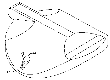
Soupape d'égalisation pour un clapet dans une soupape de sécurité souterraine. Un plongeur effilé est sollicité par un ressort compact disposé dans l'alésage de plongeur. Le ressort est supporté par une bague en C s'étendant dans une rainure périphérique autour de l'alésage de plongeur.


Abrégé anglais

An equalizer valve for a flapper in a subsurface safety valve is described. A tapered plunger is biased by compact spring disposed in the plunger bore. The spring is supported by a C-shaped ring extending into a peripheral groove around the plunger bore.

Revendications

Note : Les revendications sont présentées dans la langue officielle dans laquelle elles ont été soumises.


-6-
What is claimed is:
1. An equalizing system for a flapper in a well valve comprising:
a flapper having a bore therethrough; and
a plunger, having a longitudinal axis and an outer periphery
about said axis, and extending through said bore and biased into selective
sealing contact therewith, said biasing accomplished by an annularly shaped
biasing member disposed in a space defined between said bore and about
said periphery of said plunger.
2. The system of claim 1, wherein:
said biasing member comprises at least one wave spring.
3. The system of claim 1, wherein:
said biasing member comprises at least one Bellville washer.
4. The system of claim 1, wherein:
said biasing member comprises at least one coiled spring.
5. An equalizing system for a flapper in a well valve comprising:
a flapper having a cylindrical bore therethrough; and
a cylindrically shaped plunger, having a longitudinal axis and an
outer periphery about said axis, and extending through said bore and biased
into selective sealing contact therewith, a travel stop for said plunger being
disposed in an annular space in said bore defined between said outer
periphery of said plunger and said bore.
6. The system of claim 5, further comprising:
at least one spring in said bore to create said bias.
7. The system of claim 6, further comprising:
at least one wave spring in said bore to create said bias.

-7-
8. The system of claim 6, further comprising:
at least one Bellville washer in said bore to create said bias.
9. The system of claim 6, further comprising:
at least one coiled spring in said bore to create said bias.
10. The system of claim 6, wherein:
said spring is supported by said travel stop.
11. The system of claim 10, wherein:
said travel stop is disposed in a groove circumscribing said bore.
12. The system of claim 11, wherein:
said travel stop further comprises a snap ring.
13. An equalizing system for a flapper in a well valve comprising:
a flapper having a cylindrical bore therethrough; and
a plunger, having a longitudinal axis and an outer cylindrical
periphery about said axis, and extending through said bore and biased from
within said bore into selective sealing contact therewith, said bore
conforming
to the shape of said periphery.
14. The system of claim 13, wherein:
said plunger is retained by a retainer mounted in said bore.
15. The system of claim 14, wherein:
said bias is applied by at least one spring supported by said
retainer.
16. The system of claim 15, wherein:
said spring comprises a wave spring.

-8-
17. The system of claim 15, wherein:
said retainer comprises a snap ring.
18. The system of claim 15, wherein:
said retainer is disposed in a groove surrounding said bore.
19. The system of claim 13, wherein:
said plunger comprises a projection extending from said
periphery for selective sealing in said bore, said projection, when pushed
against said bias out of sealing contact, directs flow past said plunger
radially,
in a direction away from said longitudinal axis, to get around said
projection.

Description

Note : Les descriptions sont présentées dans la langue officielle dans laquelle elles ont été soumises.


CA 02364329 2001-12-05
EQUALIZING FLAPPER FOR DOWNHOLE SAFETY VALVES
FIELD OF THE INVENTION
The field of this invention related to equalizing valves mounted
in ninety degree rotatable closure members, known as flappers, and more
particularly to biasing systems to keep such equalizing valves in a closed
position.
BACKGROUND OF THE INVENTION
Typically, a well completion includes a sub-surface safety valve.
This valve is actuated from the surface using a hydraulic control system with
control lines running from the surface to the valve location. These valves
feature a closure member which is rotatable through an arc of ninety degrees.
The control system pressure is used to move a hollow tube, known as a flow
tube, downwardly, usually against a return spring. The downward movement
of the flow tube rotates the flapper downwardly and out of the way to allow
flow from the producing formation to reach the surface through the flow tube.
Removal of pressure from the control system allowed the return spring to bias
the flow tube upward, whereupon another spring on the flapper urged it to the
closed position, blocking the opening in the flow tube
With the flapper in the closed position, formation pressure builds
up on the closed flapper. In this intended mode of operation, the flapper
holds
back the flow from the formation in order to allow for safe well operation.
The
problem that arises occurs when the well needs to be placed in service at a
later time. The flapper must then be opened. However, at this time there may
be substantial differential pressure acting on substantially the entire cross-
sectional area of the flapper. Aggravating this differential pressure problem
would be a situation in the well bore above the closed flapper where
thousands of feet of the tubing was gas filled or filled with a light density
fluid.
The presence of gas or light weight fluids above the flapper had, in the past,
required that such fluids be replaced with heavier fluid to eliminate or
reduce
differential pressure across the flapper prior to actuation of the flow tube.
The
fluid replacement procedure was costly as well as time consuming and better

CA 02364329 2004-05-12
-2-
methods were developed to expedite the re-opening of the flapper under
conditions of high differential pressure.
The equalizing valve in the flapper design was developed to
addressed this issue. This prior art design is illustrated in Fig. 1. A
flapper 10
is shown in perspective with a vertical segment 12 machined out adjacent an
edge 14. Undercuts 16 and 18 straddle the vertical segment 12 to allow for
placement of a leaf spring 20 therein. Leaf spring 20 straddles bore 22 in
which is disposed a plunger 24. Plunger 24 has a taper 26 which is biased
against a mating edge or surface in bore 22. The plunger 24 is situated so
that a flow tube (not shown), when urged downwardly by a control system will
first contact plunger 24 and move it against the bias of leaf spring 20. Thus,
before the flapper 10 begins to move, the taper 26 has come off of its mating
edge or surface in the bore 22 to equalize pressure on the flapper 10. Those
skilled in the art will appreciate that the view in Fig. 1 illustrates the
down hole
side of the flapper and that the flow tube is positioned on the opposite side
of
the flapper from which location it can make initial contact with the extending
plunger 24.
There was a weakness in the design described above which , in
some cases, resulted in leakage past taper 26 and its mating surface in bore
22. The reason this happened is directly related to the amount of the flapper
10 that had to be machined away to form the removed vertical segment 12
and its adjacent undercuts 16 and 18. The removal of so much metal to
accommodate the leaf spring 20 weakened the flapper 10 sufficiently to allow
distortion of bore 22 with resulting leakage past taper 26.
Accordingly, the objective of the present invention is to improve
the design of the prior art Fig. 1 so as to eliminate the leakage problem
under
conditions of high differential pressure across the flapper 10. This and other
advantages will become apparent to those skilled in the art from a review of
the preferred embodiment, described below.
Relevant to the present invention are U.S. Patents: 6,079,947;
5,884,705; 5,503,229; and 5,752,569.

CA 02364329 2004-05-12
-3-
SUMMARY OF THE INVENTION
An equalizer valve for a flapper in a subsurface safety valve is
described. A tapered plunger is biased by compact spring disposed in the
plunger bore. The spring is supported by a retaining ring which may be a C-
shaped ring extending into a peripheral groove around the plunger bore.
According to one aspect of the present invention there is
provided an equalizing system for a flapper in a well valve comprising:
a flapper having a bore therethrough; and
a plunger, having a longitudinal axis and an outer periphery
about said axis, and extending through said bore and biased into selective
sealing contact therewith, said biasing accomplished by an annularly shaped
biasing member disposed in a space defined between said bore and about
said periphery of said plunger.
According to another aspect of the present invention there is
provided an equalizing system for a flapper in a well valve comprising:
a flapper having a cylindrical bore therethrough; and
a cylindrically shaped plunger, having a longitudinal axis and an
outer periphery about said axis, and extending through said bore and biased
into selective sealing contact therewith, a travel stop for said plunger being
disposed in an annular space in said bore defined between said outer
periphery of said plunger and said bore.
According to yet another aspect of the present invention there is
provided an equalizing system for a flapper in a well valve comprising:
a flapper having a cylindrical bore therethrough; and
a plunger, having a longitudinal axis and an outer cylindrical
periphery about said axis, and extending through said bore and biased from
within said bore into selective sealing contact therewith, said bore
conforming
to the shape of said periphery.
BRIEF DESCRIPTION OF THE DRAWINGS
An embodiment of the present invention will now be described
more fully with reference to the accompanying drawings in which:

CA 02364329 2004-05-12
-4-
Figure 1 is a perspective view of a prior art equalizer design for
a flapper:
Figure 2 is a perspective view of the equalizer valve of the
present invention;
Figure 3 is an elevational view of the equalizer valve of the
present invention; and
Figure 4 is an exploded view of the equalizer valve of the
present invention.
DETAILED DESCRIPTION OF THE PREFERRED EMBODIMENT
Referring to Fig. 3, the flapper 28 is shown to best illustrate the
extension of the plunger 30 so as to position it for selective contact with a
downwardly moving flow tube, schematically represented by arrow 32.
Plunger 30 resides in bore 34, which is preferably narrow. Bore 34 has a mill
flat 36, best seen in Fig. 4. The plunger 30 has a mating taper 38 which
makes sealing contact with mill flat 36. Other configurations for sealing
apart
from mill flat 36 and taper 38 can be used without departing from the
invention. For example, sealing can be metal to metal at an end of plunger
30. Alternatively the sealing can involve a resilient seal or seals or could
involve metal to metal contact at other locations of plunger 30.
A bias on plunger 30 is provided by a spring 40 which is
retained in bore 34 by a retainer such as c-ring 42. In the preferred
embodiment the spring 42 is a wave spring. This type of spring is preferred
because it provides a relatively large closing force when longitudinally
compressed a short distance as compared with, for example, a coiled spring.
Wave springs are available from Smalley Steel Company of Wheeling, Illinois.
They feature the ability to fit in small spaces and yet to provide the
requisite
force. In the case of a flapper 28 there is a limited space available dictated
by
the thickness near edge 44 where contact with the flow tube (represented by
arrow 32) has to occur.

CA 02364329 2004-05-12
-5-
Figs. 2 and 4 illustrate how much less metal needs to be
removed to accommodate spring 40 than the prior art design depicted in Fig.
1. Very little material beyond the diameter of taper 38 on plunger 30 needs to
be removed. A peripheral groove 46 is machined in bore 34 to accept a
retainer, such as, the c-ring 42, as shown in Fig. 3. Spring 40, supported by
c-
ring 42 puts a closing force on plunger 30 by forcing its taper 38 against
mill
flat 36 in bore 34. This closing force is overcome by the flow tube force
represented by arrow 32 such that equalizing across flapper 28 occurs before
the flapper 28 is actually rotated by the flow tube itself.
Those skilled in the art will notice that the removed segment 48
out of flapper 28 is considerably smaller than the vertical segment 12 and
undercuts 16 and 18 shown as removed from flapper 10. As a result, under
extreme differential pressures there is no distortion in bore 34 which could
cause leakage between mill flat 36 and taper 38.
Removed segment 48 may be slightly larger than bore 34 to
facilitate the machining of groove 46 and the subsequent insertion of c-ring
42.
While spring 40 is preferably a wave spring other types of low
profile biasing mechanisms are within the scope of the invention. Such
alternatives can include coil springs or one or more Belleville washers. Yet
other biasing systems that permit a minimization of the size of removed
segment 48 are within the scope of the invention.
The above description of the preferred embodiment is illustrative
and is not intended to be the full limits of the invention which is depicted
in the
appended claims.

Dessin représentatif
Une figure unique qui représente un dessin illustrant l'invention.
États administratifs

2024-08-01 : Dans le cadre de la transition vers les Brevets de nouvelle génération (BNG), la base de données sur les brevets canadiens (BDBC) contient désormais un Historique d'événement plus détaillé, qui reproduit le Journal des événements de notre nouvelle solution interne.

Veuillez noter que les événements débutant par « Inactive : » se réfèrent à des événements qui ne sont plus utilisés dans notre nouvelle solution interne.

Pour une meilleure compréhension de l'état de la demande ou brevet qui figure sur cette page, la rubrique Mise en garde , et les descriptions de Brevet , Historique d'événement , Taxes périodiques et Historique des paiements devraient être consultées.

Historique d'événement

Description Date
Inactive : Périmé (brevet - nouvelle loi) 2021-12-06
Représentant commun nommé 2019-10-30
Inactive : CIB de MCD 2006-03-12
Accordé par délivrance 2005-02-08
Inactive : Page couverture publiée 2005-02-07
Préoctroi 2004-11-04
Inactive : Taxe finale reçue 2004-11-04
Un avis d'acceptation est envoyé 2004-07-28
Lettre envoyée 2004-07-28
Un avis d'acceptation est envoyé 2004-07-28
Inactive : Approuvée aux fins d'acceptation (AFA) 2004-07-20
Modification reçue - modification volontaire 2004-05-12
Inactive : Dem. de l'examinateur art.29 Règles 2003-11-12
Inactive : Dem. de l'examinateur par.30(2) Règles 2003-11-12
Lettre envoyée 2002-10-04
Inactive : Transfert individuel 2002-08-06
Modification reçue - modification volontaire 2002-06-05
Demande publiée (accessible au public) 2002-06-05
Inactive : Page couverture publiée 2002-06-04
Modification reçue - modification volontaire 2002-03-04
Inactive : CIB en 1re position 2002-02-18
Exigences de dépôt - jugé conforme 2002-01-11
Inactive : Certificat de dépôt - RE (Anglais) 2002-01-11
Lettre envoyée 2002-01-09
Demande reçue - nationale ordinaire 2002-01-09
Toutes les exigences pour l'examen - jugée conforme 2001-12-02
Exigences pour une requête d'examen - jugée conforme 2001-12-02
Inactive : Lettre de courtoisie - Preuve 2001-01-15

Historique d'abandonnement

Il n'y a pas d'historique d'abandonnement

Taxes périodiques

Le dernier paiement a été reçu le 2004-11-22

Avis : Si le paiement en totalité n'a pas été reçu au plus tard à la date indiquée, une taxe supplémentaire peut être imposée, soit une des taxes suivantes :

  • taxe de rétablissement ;
  • taxe pour paiement en souffrance ; ou
  • taxe additionnelle pour le renversement d'une péremption réputée.

Veuillez vous référer à la page web des taxes sur les brevets de l'OPIC pour voir tous les montants actuels des taxes.

Titulaires au dossier

Les titulaires actuels et antérieures au dossier sont affichés en ordre alphabétique.

Titulaires actuels au dossier
BAKER HUGHES INCORPORATED
Titulaires antérieures au dossier
JASON B. IVES
Les propriétaires antérieurs qui ne figurent pas dans la liste des « Propriétaires au dossier » apparaîtront dans d'autres documents au dossier.
Documents

Pour visionner les fichiers sélectionnés, entrer le code reCAPTCHA :


Pour visualiser une image, cliquer sur un lien dans la colonne description du document. Pour télécharger l'image (les images), cliquer l'une ou plusieurs cases à cocher dans la première colonne et ensuite cliquer sur le bouton "Télécharger sélection en format PDF (archive Zip)" ou le bouton "Télécharger sélection (en un fichier PDF fusionné)".

Liste des documents de brevet publiés et non publiés sur la BDBC .

Si vous avez des difficultés à accéder au contenu, veuillez communiquer avec le Centre de services à la clientèle au 1-866-997-1936, ou envoyer un courriel au Centre de service à la clientèle de l'OPIC.


Description du
Document 
Date
(aaaa-mm-jj) 
Nombre de pages   Taille de l'image (Ko) 
Dessin représentatif 2002-05-31 1 10
Dessins 2002-03-04 4 42
Abrégé 2001-12-05 1 9
Description 2001-12-05 4 195
Revendications 2001-12-05 3 70
Dessins 2001-12-05 4 50
Page couverture 2002-05-31 1 29
Description 2004-05-12 5 229
Revendications 2004-05-12 3 72
Page couverture 2005-01-14 1 30
Accusé de réception de la requête d'examen 2002-01-09 1 178
Certificat de dépôt (anglais) 2002-01-11 1 164
Courtoisie - Certificat d'enregistrement (document(s) connexe(s)) 2002-10-04 1 109
Rappel de taxe de maintien due 2003-08-06 1 106
Avis du commissaire - Demande jugée acceptable 2004-07-28 1 162
Correspondance 2002-01-11 1 31
Correspondance 2004-11-04 1 48