Sélection de la langue

Search

Sommaire du brevet 2364602 

Énoncé de désistement de responsabilité concernant l'information provenant de tiers

Une partie des informations de ce site Web a été fournie par des sources externes. Le gouvernement du Canada n'assume aucune responsabilité concernant la précision, l'actualité ou la fiabilité des informations fournies par les sources externes. Les utilisateurs qui désirent employer cette information devraient consulter directement la source des informations. Le contenu fourni par les sources externes n'est pas assujetti aux exigences sur les langues officielles, la protection des renseignements personnels et l'accessibilité.

Disponibilité de l'Abrégé et des Revendications

L'apparition de différences dans le texte et l'image des Revendications et de l'Abrégé dépend du moment auquel le document est publié. Les textes des Revendications et de l'Abrégé sont affichés :

  • lorsque la demande peut être examinée par le public;
  • lorsque le brevet est émis (délivrance).
(12) Brevet: (11) CA 2364602
(54) Titre français: RECOUVRE-GOUTTIERE A PERFORATIONS
(54) Titre anglais: GUTTER SHIELD
Statut: Périmé et au-delà du délai pour l’annulation
Données bibliographiques
Abrégés

Abrégé anglais


A gutter shield for protecting a gutter from the gutter shield having a
mounting
member secured to the gutter, a guard member with an elongated configuration
and
having a plurality of apertures extending therethrough to permit water
drainage into the
gutter, the mounting member also having a flexible sealing element extending
outwardly
therefrom, the flexible ceiling element being designed to seal against either
the side of the
gutter or a structural element. The device is suitable for many different
sizes of gutters.

Revendications

Note : Les revendications sont présentées dans la langue officielle dans laquelle elles ont été soumises.


The embodiments of an invention in which an exclusive property or privilege is
claimed is defined as follows:
1. A device for protecting a gutter wherein the gutter has a rear wall, a
front wall,
and a bottom wall, said walls defining a trough therebetween, said device
comprising:
a mounting member and means for securing said mounting member to said
gutter; at least one clip member for securing said device to said gutter, said
clip
member having a pair of legs extending downwardly and being designed to be
attached to a gutter retaining member extending between said rear side wall
and said
front wall.
a guard member having an elongated configuration with first and second
longitudinally extending sides;
a first side of said guard member being engageable with a first side of said
mounting member to prevent substantial vertical movement of said guard member;
said mounting member having a flexible sealing portion extending outwardly in
a direction away from said first side of said mounting member for sealing
engagement
with an adjacent structure; and
said guard member having a substantially planar portion between said first and
second sides, said substantially planar portion having a plurality of
apertures
extending therethrough.
2. The device of Claim 1 wherein said apertures are arranged in diagonal rows
extending between said rear side wall and said front wall.
3. The device of Claim 1 wherein said apertures are circular in configuration,
said
apertures having a diameter of between 2.5 and 10 mm.
4. The device of Claim 3 wherein said apertures have a diameter of between 3.0
and 4.0 mm.

5. The device of Claim 3 wherein said diagonal rows extend at an angle of
45°
with respect to said first and second side walls, said apertures forming
longitudinally
extending rows, said apertures being spaced apart by a distance of between 10
and 15
mm in said longitudinally extending rows.
6. The device of Claim 5 wherein said apertures are spaced apart by between S
and 10 mm in each diagonal row.
7. The device of Claim 1 wherein said mounting member has a recess facing said
first side of said guard member whereby said first side of said guard member
is
insertable into said recess and is moveable therein.
8. The device of Claim 7 wherein said mounting member has means for retaining
said first side of said guard member in said recess.
9. The device of Claim 1 wherein said guard member has a vertically extending
side wall adjacent said second side thereof.
10. In combination, a gutter and a gutter shield device, said gutter having a
rear
wall, a front wall, and a bottom wall, said rear wall and bottom wall defining
an open
end trough, said gutter adapted to be attached to a structure by means of a
gutter
retaining member extending between said front and rear walls to said
structure, said
gutter shield device comprising:
a mounting member, means for securing said mounting member to said gutter
retaining member, said means for securing said mounting member to said gutter
comprising a clip member having a pair of legs extending downwardly and about
said
gutter retaining member;
a guard member having an elongated configuration with first and second
longitudinally extending sides;

a first side of said guard member being engagable with a first side of said
mounting member to prevent substantial movement of said guard member;
said mounting member having a flexible sealing portion extending outwardly in
a direction away from said first side of said mounting member for sealing
engagement
with the structure; and
said guard member having a substantially planar portion between said first and
second sides, said substantially planar portion having a plurality of
apertures
extending therethrough.
11. The combination of Claim 10 wherein said mounting member has a recess
facing said first side of said gutter member whereby said first side of said
guard
member is insertable into said recess and is moveable therein.
12. The device of Claim 10 wherein said guard member has a vertically
extending
side wall adjacent said second side thereof.

Description

Note : Les descriptions sont présentées dans la langue officielle dans laquelle elles ont été soumises.

CA 02364602 2001-12-17
GUTTER SHIELD
FIELD OF THE INVENTION
The present invention relates to a shield for a rainwater gutter assembly or a
eaves
trough.
BACKGROUND OF THE INVENTION
The use of shields for gutters or eaves troughs is well known in the prior art
and
there have been many proposals for different types of shields. The purpose of
the shield
is essentially to permit passage of rainwater from the roof to the eaves
trough while
protecting the same from extraneous foreign matter such as leaves and the
like.
To date, there have been several different approaches taken. A first approach
is
utilizing a shield or a guard which is apertured and permits the passage of
rainwater while
ostensibly barring the passage of extraneous material. However, many of these
guards do
not function as desired and access must still be had to the eaves trough for
cleaning
purposes. Also, each one must be fabricated to the particular size of eaves
trough.
It has also been proposed in the art to provide relatively complex structures
wherein the eaves troughs are mounted for rotatable movement such that they
may be
emptied at desired intervals.
There have also been proposed gutters having a design wherein a cover has an
outer edge which curls downwardly and the water flow follows the curved
portion due to
surface tension to cascade into the eaves trough. However, this concept will
not
necessarily work when'the volume of water becomes sufficiently large that the
surface
tension is insufficient to cause all the water to flow into the gutter.
-1-

CA 02364602 2001-12-17
SUMMARY OF THE INVENTION
It is an object of the present invention to provide a novel gutter guard which
is
designed to fit different sizes of eaves troughs.
It is a further object of the present invention to provide a gutter guard for
an eaves
trough forwarding the rainwater into the gutter, but wherein virtually all
foreign matter is
excluded.
It is a further object of the present invention to provide a gutter guard for
an eaves
trough wherein the gutter guard includes a flexible member design to sealingly
abut an
adjacent structure.
According to one aspect of the present invention, there is provided a device
for
protecting a gutter wherein the gutter has a rear wall, a front wall, a bottom
wall, the
walls defining a trough therebetween, the device comprising a mounting member,
means
for securing the mounting member to the gutter, a guard member having an
elongated
configuration with first and second longitudinally extending post sides, a
first side of the
guard member being engageable with a first side of the mounting member to
prevent
substantial vertical movement of the guard member, the mounting member having
a
flexible sealing portion extending outwardly in a direction away from the
first side of the
mounting member for sealing engagement with an adjacent structure, and the
guard
member having a substantially planar portion between the first and second
sides, the
substantially planar portion having a plurality of apertures extending
therethrough.
The device of the present invention is preferably, at least partially, formed
of a
plastic material. However, it will be understood that other materials may be
used and
indeed, the gutter guard may be formed by a combination of materials.
-2-

CA 02364602 2001-12-17
The device o~'the present invention provides a guard for the eaves trough to
prevent foreign matter from entering into the eaves trough. This is achieved
through
appropriate sizing of the apertures formed therein. In this respect, the
aperture size and
aperture placement permit adequate drainage of the water through the apertures
into the
eaves trough while substantially excluding any foreign matter which rained on
the top
and which normally will be removed by the elements of wind and the like. The
size of
the apertures prevents clogging of the device.
The apertures preferably extend in diagonal lines at an angle of 45°
with respect to
the gutter length. In the preferred embodiments, the apertures have an
aperture of
between 2.5 and 10 mm and even more preferably between 3.0 and 4.0 mm. As the
apertures are arranged in diagonal rows, they are also preferably arranged in
longitudinally extending rows. In a longitudinally extending row, the
apertures are
spaced apart by a distance of between 10 and 15 mm while in a diagonal row,
they are
spaced apart by a distance of between 5 and 10 mm.
As will be appreciated, during a period of heavy rain or the like, the
drainage may
not be instantaneous and accordingly, there is preferably provided a
vertically extending
wall adjacent the front wall of the gutter to prevent overflow.
BRIEF DESCRIPTION OF THE DRAWINGS
Having thus generally described the invention, reference will be made to the
accompanying drawings illustrating an embodiment thereof, in which:
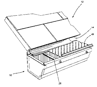
Figure 1 is a perspective view of a portion of an eaves trough and surrounding
structure having the gutter guard of the present invention secured in place;
Figure 2 is a cross sectional view thereof;
-3-

CA 02364602 2001-12-17
Figure 2a is a cross sectional view of a modified arrangement;
Figure 3 is a cross sectional view of the gutter guard; and
Figure 4 is an enlarged view of a clip member which may be used in the present
invention.
DESCRIPTION OF THE PREFERRED EMBODIMENTS
Referring to the drawings in greater detail and by reference characters
thereto, it is
illustrated a gutter generally designated by reference numeral 10 and which is
attached to
a roof generally designated by reference numeral 12. As is conventional, there
is
provided a drip edge 14 extending from under the edge of the roof.
Gutter 10 is a conventional gutter and includes a back wall 16 lying
substantially
adjacent to the facia of the structure. Extending between a front wall 20 and
back
wall 16 is a bottom 18. Front wall 20 includes a front top wall 22 which
extends
horizontally inwardly and which is folded under to present a finished edge as
is
conventional. Gutter 10 is secured by means of nails 24 which pass through an
internal
shroud 26, again as is well known in the art.
The device of the present invention includes a mounting member generally
designated by reference numeral 30 and which will now be referred to. Mounting
member 30 has a base 32 which extends through to an end wall 34. In turn, end
wall 34
merges with a top wall 36 which terminates in a downwardly extending flange
38. A
recess 40 is defined between flange 38 and walls 32, 34 and 36. A flexible
sealing
member 42 extends outwardly to seal against drip edge 14.
The device also includes a second member 44 which includes a main planar body
portion 46 which has a plurality of apertures 48 formed therein. Apertures 48,
as may be
-4-

CA 02364602 2001-12-17
seen, extend in diagonal lines at an angle of 45 degrees with respect to the
length of the
body 46. For a best functioning of the device, the sizing and placement of the
apertures
is important. The apertures preferably have a diameter of between 2.5 and 10
mm and
more preferably between 3.0 and 4.0 mm. Also, the spacing is preferably such
that in a
longitudinally extending row, the apertures are spaced between 10 and 15 mm
apart with
a spacing of between 5 and 10 mm in a diagonal row. It has been found that
these
spacings and sizes of apertures permit water to flow into the gutter while the
sizes are
such that substantially all foreign matter is excluded.
The second member 44 includes a flange 50 which extends inwardly along one
side of body 46 for reasons which will become apparent hereinbelow. Flange 50,
together with body portion 46, defines a V-shaped configuration.
At its other side, body 46 has a vertical inner wall 52 which is radiused to
join a
vertical outer wall 54. A horizontal portion 56 extends outwardly from
vertical outer
wall 54 and terminates in a reverse edge.
In use, first member 30 is secured adjacent rear wall 16 of gutter 10. To this
end,
there are provided clip members 66 which are secured to the underside of wall
32 of first
member 30. In one embodiment, as shown in Figure 3, each clip member 66
comprises a
pair of inwardly facing C-shaped elements 68 defining an opening 70
therebetween.
These are then mounted on shroud 26 surrounding a nail 24.
As may be seen in Figure 4, the end of body 46 having flange 50 may be
inserted
into the cavity 40. Flange 50 will prevent withdrawal of second member 44.
Vertical inner side wall 52 forms a barner to prevent overflow of the
rainwater
from the surface of body portion 46.
-S-

CA 02364602 2001-12-17
As seen in Figure 2a, flexible sealing member 42 may seal against the wall to
which the gutter is mounted or indeed to the gutter itself. It is the
flexibility of sealing
member 42 which allows adjustment of the gutter guard to fit different size
gutters.
It will be understood that the above described embodiment is for purposes of
illustration only and that changes or modifications may be made thereto
without
departing from the spirit and scope of the invention.
-6-

Dessin représentatif
Une figure unique qui représente un dessin illustrant l'invention.
États administratifs

2024-08-01 : Dans le cadre de la transition vers les Brevets de nouvelle génération (BNG), la base de données sur les brevets canadiens (BDBC) contient désormais un Historique d'événement plus détaillé, qui reproduit le Journal des événements de notre nouvelle solution interne.

Veuillez noter que les événements débutant par « Inactive : » se réfèrent à des événements qui ne sont plus utilisés dans notre nouvelle solution interne.

Pour une meilleure compréhension de l'état de la demande ou brevet qui figure sur cette page, la rubrique Mise en garde , et les descriptions de Brevet , Historique d'événement , Taxes périodiques et Historique des paiements devraient être consultées.

Historique d'événement

Description Date
Exigences relatives à la révocation de la nomination d'un agent - jugée conforme 2021-04-01
Le délai pour l'annulation est expiré 2011-12-19
Lettre envoyée 2010-12-17
Accordé par délivrance 2005-06-07
Inactive : Page couverture publiée 2005-06-06
Inactive : Taxe finale reçue 2005-03-21
Préoctroi 2005-03-21
Un avis d'acceptation est envoyé 2005-02-10
Lettre envoyée 2005-02-10
Un avis d'acceptation est envoyé 2005-02-10
Inactive : Approuvée aux fins d'acceptation (AFA) 2005-02-02
Modification reçue - modification volontaire 2004-12-10
Inactive : Dem. de l'examinateur par.30(2) Règles 2004-11-01
Inactive : Dem. de l'examinateur art.29 Règles 2004-11-01
Demande publiée (accessible au public) 2003-06-17
Inactive : Page couverture publiée 2003-06-16
Lettre envoyée 2003-02-04
Requête d'examen reçue 2003-01-06
Exigences pour une requête d'examen - jugée conforme 2003-01-06
Toutes les exigences pour l'examen - jugée conforme 2003-01-06
Inactive : CIB en 1re position 2002-02-20
Demande reçue - nationale ordinaire 2002-01-11
Inactive : Certificat de dépôt - Sans RE (Anglais) 2002-01-11
Déclaration du statut de petite entité jugée conforme 2001-12-17

Historique d'abandonnement

Il n'y a pas d'historique d'abandonnement

Taxes périodiques

Le dernier paiement a été reçu le 2004-12-01

Avis : Si le paiement en totalité n'a pas été reçu au plus tard à la date indiquée, une taxe supplémentaire peut être imposée, soit une des taxes suivantes :

  • taxe de rétablissement ;
  • taxe pour paiement en souffrance ; ou
  • taxe additionnelle pour le renversement d'une péremption réputée.

Les taxes sur les brevets sont ajustées au 1er janvier de chaque année. Les montants ci-dessus sont les montants actuels s'ils sont reçus au plus tard le 31 décembre de l'année en cours.
Veuillez vous référer à la page web des taxes sur les brevets de l'OPIC pour voir tous les montants actuels des taxes.

Historique des taxes

Type de taxes Anniversaire Échéance Date payée
Taxe pour le dépôt - petite 2001-12-17
Requête d'examen - petite 2003-01-06
TM (demande, 2e anniv.) - petite 02 2003-12-17 2003-11-28
TM (demande, 3e anniv.) - petite 03 2004-12-17 2004-12-01
Taxe finale - petite 2005-03-21
TM (brevet, 4e anniv.) - petite 2005-12-19 2005-11-23
TM (brevet, 5e anniv.) - petite 2006-12-18 2006-12-15
TM (brevet, 6e anniv.) - petite 2007-12-17 2007-11-29
TM (brevet, 7e anniv.) - petite 2008-12-17 2008-11-20
TM (brevet, 8e anniv.) - petite 2009-12-17 2009-11-26
Titulaires au dossier

Les titulaires actuels et antérieures au dossier sont affichés en ordre alphabétique.

Titulaires actuels au dossier
STEPHANE BROCHU
Titulaires antérieures au dossier
S.O.
Les propriétaires antérieurs qui ne figurent pas dans la liste des « Propriétaires au dossier » apparaîtront dans d'autres documents au dossier.
Documents

Pour visionner les fichiers sélectionnés, entrer le code reCAPTCHA :


Pour visualiser une image, cliquer sur un lien dans la colonne description du document. Pour télécharger l'image (les images), cliquer l'une ou plusieurs cases à cocher dans la première colonne et ensuite cliquer sur le bouton "Télécharger sélection en format PDF (archive Zip)" ou le bouton "Télécharger sélection (en un fichier PDF fusionné)".

Liste des documents de brevet publiés et non publiés sur la BDBC .

Si vous avez des difficultés à accéder au contenu, veuillez communiquer avec le Centre de services à la clientèle au 1-866-997-1936, ou envoyer un courriel au Centre de service à la clientèle de l'OPIC.


Description du
Document 
Date
(aaaa-mm-jj) 
Nombre de pages   Taille de l'image (Ko) 
Dessin représentatif 2003-05-25 1 15
Abrégé 2001-12-16 1 16
Description 2001-12-16 6 242
Revendications 2001-12-16 2 74
Dessins 2001-12-16 3 52
Revendications 2004-12-09 3 103
Certificat de dépôt (anglais) 2002-01-10 1 164
Accusé de réception de la requête d'examen 2003-02-03 1 173
Rappel de taxe de maintien due 2003-08-18 1 106
Avis du commissaire - Demande jugée acceptable 2005-02-09 1 161
Avis concernant la taxe de maintien 2011-01-27 1 171
Taxes 2003-11-27 1 24
Taxes 2004-11-30 1 21
Correspondance 2005-03-20 1 27
Taxes 2005-11-22 1 21