Sélection de la langue

Search

Sommaire du brevet 2366204 

Énoncé de désistement de responsabilité concernant l'information provenant de tiers

Une partie des informations de ce site Web a été fournie par des sources externes. Le gouvernement du Canada n'assume aucune responsabilité concernant la précision, l'actualité ou la fiabilité des informations fournies par les sources externes. Les utilisateurs qui désirent employer cette information devraient consulter directement la source des informations. Le contenu fourni par les sources externes n'est pas assujetti aux exigences sur les langues officielles, la protection des renseignements personnels et l'accessibilité.

Disponibilité de l'Abrégé et des Revendications

L'apparition de différences dans le texte et l'image des Revendications et de l'Abrégé dépend du moment auquel le document est publié. Les textes des Revendications et de l'Abrégé sont affichés :

  • lorsque la demande peut être examinée par le public;
  • lorsque le brevet est émis (délivrance).
(12) Demande de brevet: (11) CA 2366204
(54) Titre français: METHODE ET DISPOSITIF D'INSTALLATION DE TUBAGE AU MOYEN D'UN ENGIN DE FORAGE A ENTRAINEMENT PAR LE HAUT
(54) Titre anglais: METHOD AND APPARATUS FOR INSTALLING CASING USING A TOP DRIVE DRILLING RIG
Statut: Réputée abandonnée et au-delà du délai pour le rétablissement - en attente de la réponse à l’avis de communication rejetée
Données bibliographiques
(51) Classification internationale des brevets (CIB):
  • E21B 19/08 (2006.01)
  • E21B 19/16 (2006.01)
(72) Inventeurs :
  • MCALLISTER, BRYON (Canada)
  • MCALLISTER, GEORGE (Canada)
  • MCALLISTER, KENT (Canada)
  • MCALLISTER, NEIL (Canada)
  • MCALLISTER, LESLIE (Canada)
  • MCALLISTER, SHELDON (Canada)
(73) Titulaires :
  • BRYON MCALLISTER
  • GEORGE MCALLISTER
  • KENT MCALLISTER
  • NEIL MCALLISTER
  • LESLIE MCALLISTER
  • SHELDON MCALLISTER
(71) Demandeurs :
  • BRYON MCALLISTER (Canada)
  • GEORGE MCALLISTER (Canada)
  • KENT MCALLISTER (Canada)
  • NEIL MCALLISTER (Canada)
  • LESLIE MCALLISTER (Canada)
  • SHELDON MCALLISTER (Canada)
(74) Agent: DOUGLAS B. THOMPSONTHOMPSON, DOUGLAS B.
(74) Co-agent:
(45) Délivré:
(22) Date de dépôt: 2001-12-21
(41) Mise à la disponibilité du public: 2003-06-21
Requête d'examen: 2007-03-01
Licence disponible: S.O.
Cédé au domaine public: S.O.
(25) Langue des documents déposés: Anglais

Traité de coopération en matière de brevets (PCT): Non

(30) Données de priorité de la demande: S.O.

Abrégés

Abrégé anglais


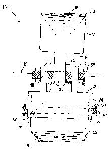
A method and apparatus for installing casing with a top
drive drilling rig. A first step involves securing a first
body to a rotating top head of the top drive drilling unit.
A second step involves securing a second body to a length of
casing. A third step involves detachably coupling the first
body and the second body so that the second body rotates with
the first body. This method allows for rapid connection to the
top head of the top drive. The process can be further
accelerated by using several of the second bodies. While one
of the second bodies is being used, another can be secured to
the next length of casing in readiness for installation.

Revendications

Note : Les revendications sont présentées dans la langue officielle dans laquelle elles ont été soumises.


8
THE EMBODIMENTS OF THE INVENTION IN WHICH AN EXCLUSIVE PROPERTY
OR PRIVILEGE IS CLAIMED ARE DEFINED AS FOLLOWS:
1. An apparatus for installing casing with a top drive
drilling rig, comprising:
a first body securable to a rotating top head of the top
drive drilling unit;
a second body securable to a length of casing;
means for detachably coupling the first body and the
second body so that the second body rotates with the first
body.
2. The apparatus as defined in Claim 1, wherein the first body
has a threaded coupling which is adapted to engage a mating
threaded coupling carried by the rotating top head of the top
drive drilling rig.
3. The apparatus as defined in Claim 1, wherein the second
body has a threaded coupling which is adapted to engage a
mating threaded coupling of the length of casing.
4. The apparatus as defined in Claim 1, wherein the means for
detachably coupling the first body and the second body includes
a first pin receiver on the first body, a second pin receiver
on the second body, and a removable pin that is adapted to
engage the first pin receiver and the second pin receiver to
detachably couple the first body and the second body.
5. The apparatus as defined in Claim 4, wherein one of the
first pin receiver and the second pin receiver has a single
lobe with an aperture and the other of the first pin receiver
and the second pin receiver has a pair of spaced lobes each of
which have apertures, the single lobe being positionable
between the spaced lobes.
6. The apparatus as defined in Claim 2, wherein the second
body has a receptacle and an insert is provided which carries

9
the threaded coupling, means being provided for detachably
securing the insert within the receptacle.
7. The apparatus as defined in Claim 6, wherein the second
body has pin receiving apertures extending through the
receptacle and the insert has pin receiving apertures, the
insert being detachably secured within the receptacle by a
second removable pin when engages both the pin receiving
apertures which extend through the receptacle of the second
body and the pin receiving apertures of the insert.

10
8. An apparatus for installing casing with a top drive
drilling rig, comprising:
a first body having a first end and a second end, a
threaded coupling being positioned at the first end, the
threaded coupling being adapted to engage a mating threaded
coupling carried by a rotating top head of the top drive
drilling rig, a first pin receiver being positioned at the
second end;
a second body having a first end and a second end, a
receptacle being positioned at the second end and a second pin
receiver being positioned at the first end;
a first removable pin engaging the first pin receiver and
the second pin receiver to detachably couple the first body and
the second body, such that a rotational force exerted upon the
first body by the rotating top head is transmitted to the
second body so that the second body rotates with the first
body; and
an insert which carried a threaded coupling which is
adapted to engage a mating threaded coupling on a length of
casing, means being provided for detachably non-rotatably
securing the insert within the receptacle of the second body,
such that a rotational force exerted upon the second body is
transmitted to the insert so that the insert rotates with the
second body.
9. The apparatus as defined in Claim 8, wherein the first body
and the second body are adapted to pivot about a first pivot
axis provided by the first removable pin.
10. The apparatus as deffined in Claim 8 , wherein the first pin
receiver has a single lobe with an aperture and the second pin
receiver has a pair of spaced lobes each of which have
apertures, the single lobe being positionable between the
spaced lobes to engage the first removable pin.
11. The apparatus as defined in Claim 8, wherein the second

11
body has pin receiving apertures extending through the
receptacle and the insert has pin receiving apertures, the
insert being detachably secured within the receptacle by a
second removable pin when engages both the pin receiving
apertures which extend through the receptacle of the second
body and the pin receiving apertures of the insert.

12
12. A method for installing casing with a top drive drilling
rig, comprising the steps of:
securing a first body to a rotating top head of the top
drive drilling unit;
securing a second body to a length of casing;
detachably coupling the first body and the second body so
that the second body rotates with the first body.
13. The method as defined in Claim 12, several of the second
bodies being provided, such that while one of the several
second bodies is being attached to the first body, used to
rotate a length of casing and detached, the other of the
several second bodies are being secured to the next lengths of
casing to be installed.

Description

Note : Les descriptions sont présentées dans la langue officielle dans laquelle elles ont été soumises.


CA 02366204 2001-12-21
1
TITLE OF THE INVENTION:
Method and Apparatus for Installing Casing Using A Top
Drive Drilling Rig
FIELD OF THE INVENTION
The present invention relates to a method and apparatus
for installing casing using a top drive drilling rig.
BACKGROUND OF THE INVENTION
The casing installation apparatus currently in use with
top drive drilling rigs has a body that has a female threaded
connection at a first end and a male threaded connection at a
second end. The male threaded connection at the second end is
used to engage a length of casing. The female threaded
connection at the first end is threaded into a lifting
apparatus and lifted by a line up the oil rig derrick to a rig
hand. Once at the top of the derrick, the rig hand makes a
transfer detaching the female threaded connection from the
lifting apparatus and engaging it with a rotating top head of
the top drive unit of the drilling rig. Care must be taken
during the transfer by the rig hand at the top of the derrick.
Care also must be taken when engaging the rotating top head,
not to inadvertently loosen the male threaded connection
engaging the casing. Once the rotating top head is engaged,
the rotating top head is used to spin lengths of casing
together. The operation, as described above, tends to be a
relatively slow and labour intensive process.
SUMMARY OF THE INVENTION
What is required is a method and apparatus for installing
casing with a top drive drilling rig which will accelerate the
installation process.
According to one aspect of the present invention there is
provided a method for installing casing with a top drive
drilling rig. A first step involves securing a first body to
a rotating top head of the top drive drilling unit. A second

CA 02366204 2001-12-21
2
step involves securing a second body to a length of casing.
A third step involves detachably coupling the first body and
the second body so that the second body rotates with the first
body.
With the method, as described above, the first body
remains permanently attached to the top head of the top drive
unit. The first body and the second body can be rapidly
connected and disconnected, by means of the detachable coupling
as will hereinafter be further described. The process can be
further accelerated by providing several of the second bodies.
While one of the second bodies is being attached to the first
body, used to rotate a length of casing and detached; the other
of the second bodies placed in readiness by being secured to
the next lengths of casing to be installed.
According to another aspect of the present invention there
is provided an apparatus for installing casing with a top drive
drilling rig which includes a first body securable to a
rotating top head of the top drive drilling unit and a second
body securable to a length of casing. Means is provided for
detachably coupling the first body and the second body so that
the second body rotates with the first body.
There are various forms of couplings that can be used to
secure the first body to the rotating top head of the top drive
drilling unit. Beneficial results have been obtained when the
first body has a threaded coupling which is adapted to engage
a mating threaded coupling carried by the rotating top head of
the top drive drilling rig. It will be understood, however,
that the coupling need not be a threaded coupling.
Similarly, there are various forms of couplings that can
be used to secure the second body to the length of casing.
Beneficial results have been obtained when the second body has
a threaded coupling which is adapted to engage a mating
threaded coupling of the length of casing. It will be

' CA 02366204 2001-12-21
3
understood, however, that the coupling need not be a threaded
coupling.
It is preferred that the means for detachably coupling the
first body and the second body includes a first pin receiver
on the first body and a second pin receiver on the second body.
This enables a removable pin to be used that is adapted to
engage the first pin receiver and the second pin receiver to
detachably couple the first body and the second body. It will
be understood that although this type of coupling is preferred
due to the speed of connection and disconnection, other forms
of toque transmitting couplings would also be suitable.
Although beneficial results may be obtained through the
use of the apparatus, as described above, there are several
different sizes of casing with which the apparatus must be
used. Even more beneficial results may, therefore, be obtained
when the second body has a receptacle and an insert is provided
which carries the threaded coupling. Means is provided for
detachably securing the insert within the receptacle, so that
the size of threaded coupling can be changed to suit different
sizes of casing and different application requirements.
It is preferred that the first body and the second body
be adapted to pivot about a first pivot axis provided by the
first removable pin. This provides for easier alignment of the
first body and the second body and, thereby, promotes a more
rapid connection.
BRIEF DESCRIPTION OF THE DRAWINGS
These and other features of the invention will become more
apparent from the following description in which reference is
made to the appended drawings, the drawings are for the purpose
of illustration only and are not intended to in any way limit
the scope of the invention to the particular embodiment or

CA 02366204 2001-12-21
4
embodiments shown, wherein:
FIGURE 1 is a side elevation view of an apparatus for
installing casing constructed in accordance with the teachings
of the present invention.
FIGURE 2 is a side elevation view of the apparatus for
installing casing illustrated in FIGURE l, in use in accordance
with the teachings of the method.
DETAILED DESCRIPTION OF THE PREFERRED EMBODIMENT
The preferred embodiment, an apparatus for installing
casing using a top drive drilling rig generally identified by
reference numeral 10, will now be described with reference to
FIGURES 1 and 2.
Structure and Relationship of Parts:
Referring to FIGURE 1, apparatus 10 includes a first body
12 with a first end 14 and a second end 16. A threaded coupling
18 is positioned at first end 14. Referring to FIGURE 2,
threaded coupling 18 is adapted to engage a mating threaded
coupling 20 which is carried by a rotating top head 22 of a top
drive drilling rig generally referenced by numeral 24.
Referring to FIGURE 1, a first pin receiver 26 is positioned
at second end of body 12.
Referring to FIGURE l, a second body 28 is also provided
with a first end 30 and a second end 32. A receptacle 34 is
positioned at second end 32. A second pin receiver 36 is
positioned at first end 30. A first removable pin 38 engages
first pin receiver 26 and second pin receiver 36 to detachably
couple first body 12 and second body 28. Referring to FIGURE
2, a rotational force exerted upon first body 12 by rotating
top head 22 is transmitted to second body 28 so that second
body 28 rotates with first body 12. First body 12 and second
body 28 are adapted to pivot about a first pivot axis 40
provided by first removable pin 38.

CA 02366204 2001-12-21
Referring to FIGURE 1, in this embodiment, first pin
receiver 26 has a single lobe 42 with an aperture 44 and second
pin receiver 36 has a pair of spaced lobes 46 each of which
have also have apertures 48. Single lobe 42 is positionable
5 between spaced lobes 46 to engage first removable pin 38.
Second body 28 has pin receiving apertures 50 which extend
through receptacle 34.
Referring to FIGURE l, an insert 52 is provided which
carries a threaded coupling 54. Referring to FIGURE 2,
threaded coupling 54 is adapted to engage mating threaded
coupling 56 on a length of casing 58. Referring to FIGURE 1,
insert 52 has pin receiving apertures 60. Insert 52 is
detachably secured within receptacle 34 by a second removable
pin 62 which engages pin receiving apertures 50 that extend
through receptacle 34 of second body 28 and pin receiving
apertures 60 of insert 52. Insert 52 is non-rotatably engaged
within receptacle 34 of second body 28. A rotational force
exerted upon second body 28 is transmitted to insert 52 so that
insert 52 rotates with second body 28.
Operation:
The use and operation of apparatus for installing casing
using a top drive drilling rig generally identified by
reference numeral 10, will now be described with reference to
FIGURES 1 and 2. Referring to FIGURE 2, there is illustrated
a method for installing casing 58 with top drive drilling rig
24. First body 12, as described above, is secured to rotating
top head 22 of top drive drilling unit generally referenced by
numeral 24. Second body 28 is secured to length of casing 58.
First body 12 and second body 28 are coupled so that second
body 28 rotates with first body 12. First body 12 and second
body 28 can be rapidly connected by positioning single lobe 42
of first pin receiver 26 between spaced lobes 46 of second pin
receiver 36 and inserting first removable pin 38 through
apertures 44 and 48. First body 12 and second body 28 can be
just as rapidly disconnected by removal of first removable pin

CA 02366204 2001-12-21
6
38. The pivotal attachment along axis 40, enables attachment
without precise vertical alignment. More importantly, the
pivotal attachment along axis 40 enables attachment to me made
with casing 58 laying down at ground level.
Referring to FIGURE 2, it is preferred that several second
bodies 28 can be provided. While one of second bodies 28 is
attached to first body 12 and used to rotate a length of casing
58 before being detached, another of second bodies 28a can be
secured to the next length of casing 58a to be installed.
Referring to FIGURE l, in order to adapt apparatus 10 for
use with a different size of casing, second removable pin 62
is withdrawn and insert 52 is removed from receptacle 34. A
different insert 52 suited for the new size of casing can then
be inserted into receptacle 34. The new insert is secured in
place by inserting second removable pin 62 back through pin
receiving apertures 50 that extend through receptacle 34 of
second body 28 and pin receiving apertures 60 of insert 52.
The above described method and apparatus enables
connections to both rotating top head 22 and casing 58 to be
done at ground level. Rotating top head 22, to which first
body 12 is attached, is able to pick up casing 58, to which
second body 28 has been attached, from a position in which
casing 58 is laying down at ground level. A connection is made
between first body 12 and second body 28 by inserting pin 38.
Once pin 58 has been inserted, top drive is able to travel
straight up the derrick. Rotating top head 22 is rotated to
spin casing 58 to attach it to the casing string and the casing
string is lowered into the hole. Second body 28 is then spun
out by rotating top head 22 and lowered to ground level. Where
second body 28 is disconnected and second body 28a secured to
the next length of casing 58a is attached. It will be
appreciated that this is a much safer method as the need for
a rig hand up the derrick is eliminated, as it the transfer
from a lifting apparatus to the rotating top head. It also

CA 02366204 2001-12-21
7
allows oil rigs that are not equipped with a secondary pick up
apparatus to run casing.
It will be apparent to one skilled in the art the relative
speed that the above described method and apparatus provides
as compared to the prior art.
In this patent document, the word "comprising" is used in
its non-limiting sense to mean that items following the word
are included, but items not specifically mentioned are not
excluded. A reference to an element by the indefinite article
"a" does not exclude the possibility that more than one of the
element is present, unless the context clearly requires that
there be one and only one of the elements.
It will be apparent to one skilled in the art that
modifications may be made to the illustrated embodiment without
departing from the spirit and scope of the invention as
hereinafter defined in the Claims.

Dessin représentatif
Une figure unique qui représente un dessin illustrant l'invention.
États administratifs

2024-08-01 : Dans le cadre de la transition vers les Brevets de nouvelle génération (BNG), la base de données sur les brevets canadiens (BDBC) contient désormais un Historique d'événement plus détaillé, qui reproduit le Journal des événements de notre nouvelle solution interne.

Veuillez noter que les événements débutant par « Inactive : » se réfèrent à des événements qui ne sont plus utilisés dans notre nouvelle solution interne.

Pour une meilleure compréhension de l'état de la demande ou brevet qui figure sur cette page, la rubrique Mise en garde , et les descriptions de Brevet , Historique d'événement , Taxes périodiques et Historique des paiements devraient être consultées.

Historique d'événement

Description Date
Le délai pour l'annulation est expiré 2010-12-21
Demande non rétablie avant l'échéance 2010-12-21
Inactive : Abandon. - Aucune rép dem par.30(2) Règles 2010-03-29
Réputée abandonnée - omission de répondre à un avis sur les taxes pour le maintien en état 2009-12-21
Inactive : Dem. de l'examinateur par.30(2) Règles 2009-09-28
Modification reçue - modification volontaire 2009-05-19
Inactive : Dem. de l'examinateur par.30(2) Règles 2009-03-19
Inactive : CIB en 1re position 2008-09-22
Inactive : CIB enlevée 2008-09-22
Inactive : CIB attribuée 2008-09-22
Exigences relatives à la nomination d'un agent - jugée conforme 2008-01-02
Inactive : Lettre officielle 2008-01-02
Exigences relatives à la révocation de la nomination d'un agent - jugée conforme 2008-01-02
Inactive : Lettre officielle 2007-12-18
Requête visant une déclaration du statut de petite entité reçue 2007-12-11
Déclaration du statut de petite entité jugée conforme 2007-12-11
Demande visant la révocation de la nomination d'un agent 2007-11-16
Demande visant la nomination d'un agent 2007-11-16
Lettre envoyée 2007-03-21
Requête en rétablissement reçue 2007-03-01
Exigences pour une requête d'examen - jugée conforme 2007-03-01
Toutes les exigences pour l'examen - jugée conforme 2007-03-01
Exigences de rétablissement - réputé conforme pour tous les motifs d'abandon 2007-03-01
Inactive : Abandon.-RE+surtaxe impayées-Corr envoyée 2006-12-21
Inactive : CIB de MCD 2006-03-12
Demande publiée (accessible au public) 2003-06-21
Inactive : Page couverture publiée 2003-06-20
Inactive : CIB en 1re position 2002-03-12
Inactive : Certificat de dépôt - Sans RE (Anglais) 2002-01-31
Demande reçue - nationale ordinaire 2002-01-30

Historique d'abandonnement

Date d'abandonnement Raison Date de rétablissement
2009-12-21
2007-03-01

Taxes périodiques

Le dernier paiement a été reçu le 2008-11-26

Avis : Si le paiement en totalité n'a pas été reçu au plus tard à la date indiquée, une taxe supplémentaire peut être imposée, soit une des taxes suivantes :

  • taxe de rétablissement ;
  • taxe pour paiement en souffrance ; ou
  • taxe additionnelle pour le renversement d'une péremption réputée.

Les taxes sur les brevets sont ajustées au 1er janvier de chaque année. Les montants ci-dessus sont les montants actuels s'ils sont reçus au plus tard le 31 décembre de l'année en cours.
Veuillez vous référer à la page web des taxes sur les brevets de l'OPIC pour voir tous les montants actuels des taxes.

Historique des taxes

Type de taxes Anniversaire Échéance Date payée
Taxe pour le dépôt - petite 2001-12-21
TM (demande, 2e anniv.) - petite 02 2003-12-22 2003-12-12
TM (demande, 3e anniv.) - petite 03 2004-12-21 2004-11-23
TM (demande, 4e anniv.) - petite 04 2005-12-21 2005-12-13
TM (demande, 5e anniv.) - petite 05 2006-12-21 2006-09-26
2007-03-01
Requête d'examen - petite 2007-03-01
TM (demande, 6e anniv.) - petite 06 2007-12-21 2007-12-11
TM (demande, 7e anniv.) - petite 07 2008-12-22 2008-11-26
Titulaires au dossier

Les titulaires actuels et antérieures au dossier sont affichés en ordre alphabétique.

Titulaires actuels au dossier
BRYON MCALLISTER
GEORGE MCALLISTER
KENT MCALLISTER
NEIL MCALLISTER
LESLIE MCALLISTER
SHELDON MCALLISTER
Titulaires antérieures au dossier
S.O.
Les propriétaires antérieurs qui ne figurent pas dans la liste des « Propriétaires au dossier » apparaîtront dans d'autres documents au dossier.
Documents

Pour visionner les fichiers sélectionnés, entrer le code reCAPTCHA :


Pour visualiser une image, cliquer sur un lien dans la colonne description du document. Pour télécharger l'image (les images), cliquer l'une ou plusieurs cases à cocher dans la première colonne et ensuite cliquer sur le bouton "Télécharger sélection en format PDF (archive Zip)" ou le bouton "Télécharger sélection (en un fichier PDF fusionné)".

Liste des documents de brevet publiés et non publiés sur la BDBC .

Si vous avez des difficultés à accéder au contenu, veuillez communiquer avec le Centre de services à la clientèle au 1-866-997-1936, ou envoyer un courriel au Centre de service à la clientèle de l'OPIC.


Description du
Document 
Date
(aaaa-mm-jj) 
Nombre de pages   Taille de l'image (Ko) 
Dessin représentatif 2002-03-24 1 7
Abrégé 2001-12-20 1 19
Description 2001-12-20 7 317
Revendications 2001-12-20 5 134
Revendications 2009-05-18 2 90
Dessins 2001-12-20 2 35
Certificat de dépôt (anglais) 2002-01-30 1 164
Rappel de taxe de maintien due 2003-08-24 1 106
Rappel - requête d'examen 2006-08-21 1 116
Accusé de réception de la requête d'examen 2007-03-20 1 176
Avis de retablissement 2007-03-20 1 171
Courtoisie - Lettre d'abandon (requête d'examen) 2007-02-28 1 166
Courtoisie - Lettre d'abandon (taxe de maintien en état) 2010-02-14 1 171
Courtoisie - Lettre d'abandon (R30(2)) 2010-06-20 1 164
Taxes 2003-12-11 1 28
Taxes 2005-12-12 1 29
Taxes 2006-09-25 5 150
Correspondance 2007-11-15 5 123
Correspondance 2007-12-18 1 12
Correspondance 2008-01-01 1 15
Taxes 2007-12-10 2 71
Correspondance 2007-12-10 2 71
Taxes 2008-11-25 1 33