Note : Les descriptions sont présentées dans la langue officielle dans laquelle elles ont été soumises.
CA 02366209 2005-09-29
Method for producing a circumferentially closed hollow
profile and device f or carrying it out
FIELD OF THE INVENTION
The invention relates to a method and device for
producing a circumferentially closed hollow profile.
BACKGROUND ART
A generic method and a generic device are known from
EP 0 913 277 A1. A wishbone of a wheel suspension may
be gathered from this, said wishbone being manufactured
from a tube by means of internal high-pressure forming.
The wishbone has various cross-sectional shapes, one of
these being a flattened rectangle. In order to produce
this shape, the circular-cylindrical prebent tube is
introduced into an internal high-pressure forming tool
divided into two and, during the closing operation, is
squeezed together by the two die parts. Subsequently,
with the tool closed, the tube is expanded by means of
internal high pressure, until it is to come to bear
exactly to contour against the die impression, and
therefore the desired flat rectangular final shape is
to be obtained. During squeezing actions of this type,
which cause folds, in conjunction with volume-enlarging
expansions by means of internal high pressure, however,
a failure of the material often occurs, this being due
to an appreciable extent to the strain-hardening of the
material achieved after the squeezing operation or to
the excessive partial ironings of material in the
regions which have not yet come to bear. The failure of
the material is manifested, in this case, by the
tearing or breaking of the tube or hollow profile. The
generally known counterstays cannot be used in this
case in order to eliminate this defect, since, on the
CA 02366209 2005-09-29
- 2 -
one hand, the solid counterstays cannot become
correspondingly narrower during the squeezing of the
tube. On the other hand, the contour of the supporting
surface of the plunger is invariable, so that the
bearing contact of the tube, whether during the
squeezing operation or during the expansion phase, is
at no time equally distributed, thus leading to a non-
uniform support of the tube and therefore contributing
to the failure of the tube at this supported point or
in the regions adjacent to the counterstay.
Even a straightforward expansion of a tube of circular
cross section with high degrees of expansion, in which
the cross-sectional shape is maintained, does not
proceed, when free of support, in a reliable way in
terms of the process, since the rate of expansion
increases and the tube material would fail when it
reached its breaking elongation. In order to counteract
this, the known solid counterstays are used, by means
of which controlled expansion is possible, but limits
are also placed on it, since, of course, the tube
material comes to bear against the counterstay and
experiences there appreciable friction which is
detrimental to expansion. Moreover, all-round support
by the known counterstays is virtually impossible
during the entire expansion process, thus leading, as
mentioned above, to the failure of the tube material in
the regions adjacent to the respective counterstay.
SAY OF THE INVENTION
The object on which the invention is based is to
develop a generic method and corresponding generic
device, to the effect that it becomes possible in the
simple way to carry out a production of a hollow
profile in which, even in the case of high expansions
of the hollow profile (higher than or equal to the
breaking elongation of the material), process
reliability is ensured to a sufficient extent.
CA 02366209 2005-09-29
- 3 -
According to an aspect of the present invention, there is
provided a method for producing a circumferentially closed
hollow profile, a hollow-profile blank being expanded by
means of fluidic internal high pressure in an internal
high-pressure forming tool, after which the hollow-profile
blank assumes a final shape of the hollow profile, wherein,
during expansion, the hollow-profile blank is supported, on
at least one partial circumferential region, by means of at
least one diaphragm fastened to an inside facing the
hollow-profile blank of the tool and capable of being acted
upon by a controllable pressure acting from outside, the
diaphragm shifting back elastically as expansion
progresses, with a supporting pressure acting on the
diaphragm being reduced at the same time.
According to another aspect of the invention, there is
provided a device for producing, a circumferentially closed
hollow profile, with an internal high-pressure forming
tool, in which a hollow-profile blank is capable of being
expanded by means of fluidic internal high pressure,
wherein the tool inside has fastened to it at least one
elastic diaphragm which runs laterally of a zone of
engagement of a plunger and which covers, tight to high
pressure, a pressure-medium feed which is connected to a
pressure generator located outside the tool and which runs
as a duct through the tool and issues on the inside of the
latter towards a cavity, on which the diaphragm, having
pressure applied to it via the pressure-medium feed, is
capable of coming to bear against the hollow-profile blank
to be formed, on at least one partial circumferential
region.
According to the invention, by means of the diaphragm a
flexible counterstay is formed, which, during expansion
forming and also in other forming processes, can adapt to
any shape of the hollow-profile blank exactly to contour
and in a large area over a relatively large partial
circumferential region of the hollow-profile blank. The
CA 02366209 2005-09-29
- 4 -
contour-matching expansion and supporting force of the
diaphragm, achieved by the external application of
pressure, can be adjusted very accurately to the forming
progress by means of the simple-to-handle pressure control
parameters. Overall, that is to say, owing to the large-
area bearing contact - circumferentially complete bearing
contact if a plurality of diaphragms distributed in the
circumferential direction are used - , during each forming
phase and as a result of accurate metering of the
supporting force, the hollow-profile blank to be formed
always receives the appropriate uniform supporting force
which prevents a failure of the blank material during
expansion. The process reliability of the forming process
is thereby ensured, even in the case of very high
expansions. What is to be meant here by high expansion is
an expansion higher than or equal to the breaking
elongation of the material. A diaphragm resistant to high
pressure is simple to produce and to fasten and, overall,
constitutes only a very low outlay in terms of apparatus.
Furthermore, existing forming tools can readily be
retrofitted with the diaphragm. On account of the
elasticity of the diaphragm, during the interaction of the
two oppositely directed pressures of the constant or
increasing internal high pressure in the hollow-profile
blank and of the pressure decreasing during expansion, of
the external application of pressure to the diaphragm, the
latter is withdrawn from the cavity, while maintaining
bearing contact which is exact to contour. As a result, as
regards the entire forming process, the production of a
flattened final shape can thus also take place reliably in
terms of the process.
BRIEF DESCRIPTION OF THE DRAWINGS
The invention is explained in more detail below with
reference to an exemplary embodiment illustrated in the
drawings in which:
CA 02366209 2005-09-29
- 4a -
Figure 1 shows, in cross section, a device according to the
invention, with the diaphragm in a position of non-use,
prior to the forming of the hollow-profile blank,
Figure 2 shows, in cross section, the device from Figure 1,
with the diaphragm in the position of use, prior to the
forming of the hollow-profile blank,
Figure 3 shows, in cross section, the device from Figure 1,
with the diaphragm in the position of use, after the
expansion of the hollow-profile blank,
Figure 4 shows, in cross section, the device from Figure 1,
with the diaphragm in the position of use, after the
flattened final shape of the hollow profile is achieved.
DETAILED DESCRIPTION OF THE INVENTION
The advantageousness of the invention will become
particularly clear from the following exemplary embodiments
which do not simply refer "only" to the generation of a
hollow profile with very high expansions, but are also
aimed at the production of an additionally flattened hollow
profile, substantially more difficult with regard to
maintaining process reliability, so that a very flat, but
extremely wide
CA 02366209 2005-09-29
- 5 -
final shape of the hollow profile is achieved.
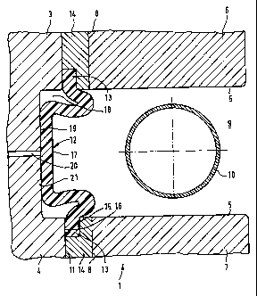
Figure 1 illustrates a device 1 for producing a
circumferentially closed flattened hollow profile 2
(Figure 4), said device consisting essentially of an
internal high-pressure forming tool divided into two
lateral tools, of a diaphragm 12 and of a flattening
device. The lateral tools may in each case be designed
in one piece, a pressure-medium feed 20 being
incorporated there. However, the lateral tools may also
have a multi-part design, divided into an upper side
tool 3 and a lower side tool 4, in which case the
pressure-medium feed 20 can run in the parting plane of
the two side tools 3 and 4. To equip the forming tools
with a blank 10, a manipulator is to be used, which
holds the blank 10 until the two pairs of side tools 3,
4 have closed, jaw-like, around the blank 10. After
forming, the ready-formed hollow profile can be removed
from the forming tool in a simple way, solely by the
action of gravity, when the side tools 3 and 4 are
moved apart from one another. It may, however, also be
envisaged, alternatively, to design the upper side tool
3 with a removable cover part, so that, with the side
tools 3, 4 closed, with the exception of the cover
part, the forming tool can be equipped via the orifice
of the forming tool occurring in the absence of the
cover part, without blank-holding manipulators being
used. The forming can commence only after the cover part
closes the equipment orifice. The removal of the finished
hollow profile takes place by gravity in the same way as in
the above-described variant of the forming tool.
Although the flattening device may simply be the pair
of side tools 3 and/or the pair of side tools 4 by
means of a correspondingly configured impression, in
the present exemplary embodiment the flattening device
comprises two mutually opposite plungers 6 and 7 which
CA 02366209 2005-09-29
- 6 -
are in alignment with one another and are guided
displaceably in leadthroughs 8 of the upper pair of
side tools 3 and of the lower pair of side tools 4 and
which are capable, in this case, of being moved into
the cavity 9 which is formed by the side tools 3 and 4
and in which the hollow-profile blank 10 initially
provided with a circular-cylindrical cross section is
received, said plungers being capable of exerting a
squeezing action on the blank 10. The use of a single
plunger may also be envisaged. The plungers 6 and 7 may
be designed continuously in adaptation to the
longitudinal extend of the internal high-pressure
forming tool and therefore to the entire formable part
of the hollow-profile blank 10 or, alternatively, be
arranged only locally in order to act upon a portion of
the blank 10. The plungers 6, 7 have a planar end face,
so that, on the one hand, the required flat final shape
of the hollow profile 2 is achieved and, on the other
hand, no indentations caused by sharp-edged
unevennesses of the plunger surface and detrimental to
process reliability occur on the blank 10.
An elastic diaphragm 12 consisting, for example, of an
elastomer or a rubber is fastened to the tool inside 11
over the length of the forming region of the hollow-
profile blank 10 and so as to run laterally of the zone
of engagement of the plungers 6 and 7 which may be
identical to the cavity 9. The fastening of the
diaphragm 12 may be carried out in many different ways,
for example unreleasably by adhesive bonding, screwing,
riveting and the like. In the present case, the
diaphragm 12 is received advantageously, so as to be
exchangeable in the event of wear, at the two flange-
like ends 13 lying transversely to the longitudinal
extent of the tool and parallel to the plungers 6 and
7, in each case in a holder 14.
The holder 14 is mounted releasably on the inside 11 of
CA 02366209 2005-09-29
- 7 _
the tool, the holder 14 having a clearance 15 which
forms a receptacle, open to the inside 11, for the
diaphragm 12 and between the walls of which and the
opposite wall portion 16 of the tool inside 11 the
diaphragm flanges 13 are clamped. Although the
diaphragm 12 can have a planar run between its flanges
13 in the position of non-use, that is to say in the
relaxed position, the diaphragm 12 has a U-shaped
design here, in order to obtain a greater reach into
the cavity 9 for the method explained later. As regards
the shape of the diaphragm 12, a recess 18 running
along the middle part 17 of the diaphragm 12 is
incorporated into the inside 11 of the tool, in order
to receive the diaphragm 12 to an extent such that,
when the diaphragm 12 is in the position of non-use and
in the last forming phase of the blank 10, the cavity 9
is diaphragm-free and therefore, on the one hand, the
diaphragm 12 does not cause an obstruction when the
cavity 9 is being equipped with a blank 10 and, on the
other hand, said diaphragm can be withdrawn from the
cavity 9 during the forming of the blank 10.
A duct-like pressure-medium feed 20 issues into the
recess bottom 19 and is connected to a pressure
generator located outside the tool. The diaphragm 12
thus covers the recess 18, together with the issue of
the pressure-medium feed 20, in a manner tight to high
pressure, with the result that, when the pressure
medium is introduced, a pressure space 22 is formed
between the recess bottom 19 and the outside 21, facing
the latter, of the diaphragm 12. By virtue of the
design of the recess 18, the pressure imparted via the
pressure medium is distributed uniformly to the entire
diaphragm 12, with the exception of the clamped flanges
13, so that local damaging elongations of the diaphragm
12 under the application of pressure are avoided and
the desired bearing contact against the hollow-profile
blank 10 is achieved to a sufficient extent over a
CA 02366209 2005-09-29
_ 8 _
partial circumferential region of the blank 10.
Although the pressure medium may be gaseous, here,
however, it is a pressure fluid because of its
incompressible properties which are highly advantageous
for support during the forming of the blank 10.
Although only a single diaphragm is illustrated in the
exemplary embodiment, a plurality of diaphragms may,
however, be lined up with one another on each side
within the scope of the invention. This is advantageous
when the blank 10 is to be formed by expansion and
flattening on only a plurality of longitudinal portions
spaced from one another. In this case, the blank 10 may
be supported to a differing extent, depending on the
desired cross-sectional shape of the hollow profile, by
means of pressure controls of the pressure fluid which
are specific to the blank portions. By contrast, the
diaphragm 12 may also extend, in a way involving a low
outlay in terms of apparatus, along the entire cavity
of the tool, specifically even where only one of the
two forming steps, expansion and flattening, or else no
forming takes place. The hollow-profile blank 10 is
thus supported over its entire longitudinal extent by
the diaphragm 12. The pressure in the pressure space 22
can be controlled according to the forming progress.
This may take place by a control of the pressure
generator or by a control of a pressure-limiting valve.
According to the drawings, it may also be envisaged
that the internal high-pressure forming tool contains
an upper tool and a lower tool instead of side tools 3,
4, with the result that the equipping of the cavity 14
can proceed relatively simply. Since, with the drawings
interpreted as being correspondingly transposed, the
diaphragm 12 connects the upper tool to the lower tool,
the diaphragm 12 is stretched and compressed during the
opening and closing of the tool, with the result that
the diaphragm 12 is exposed to increased wear. This may
CA 02366209 2005-09-29
9 -
be avoided, however, by means of a removable cover part
located in the upper tool and covering the cavity only,
the diaphragm 12 remaining unstressed during the
opening and closing movement of the forming tool. In
order to relieve the diaphragm 12 it may,
alternatively, be advantageous to rotate the internal high
pressure forming (IHF) toolarrangement consisting of the
upper tool and of the lower tool through 90° anti-
clockwise. In this case, the arrangement would have to
be configured in such a way that a diaphragm 12 is
arranged in the lower tool and a diaphragm 12 in the upper
tool, the middle part 17 of the diaphragms 12 running
horizontally then. In the alternative described, the
pressure-medium feed 20, which then, according to the
drawings, lies exactly in the parting plane of the upper
tool and lower tool and can thus be formed in each case
by a channel-like groove of the two tool halves, must be
provided separately both in the lower tool and in the
upper tool. In this version, the IHF tool can be opened
and closed, without the diaphragm 12 being in any way
subjected to mechanical stress, thus, on the one hand,
minimizing the wear of the diaphragm and, on the other
hand, optimizing access to the equipment space of the
tool.
In order to produce the flattened hollow profile 2,
first a flattening of the blank 10 may take place, the
latter subsequently being expanded in the flattened
state by means of internal high pressure. In order to
improve process reliability, prior to flattening a
pressure may be built up in the pressure space 22,
which protrudes the diaphragm 12 and expands it towards
the blank 10, until the diaphragm 12 bears snugly
against the latter on a partial circumferential region.
During subsequent flattening, in which the plungers 6,
7 move towards one another and thus reduce the cavity
9, the blank 10 is squeezed and widened in the width
direction towards the recess 18. In this case, the
CA 02366209 2005-09-29
- 10 -
pressure in the pressure space 22 must be reduced, in
order to allow this widening. In this process, the
elastic diaphragm 12 shifts out of the cavity 9 back
into its recess 1.8, until it has completely left the
zone of engagement of the plungers 6, 7. For the
expansion of the flattened blank 10, the diaphragm 12,
to which increased pressure from the pressure space 22
is applied, then stops laterally of the plungers 6, 7
and supports the blank 10 in such a way that, on the
latter, a wall 24 flush with the plunger outside 23 can
be formed. The flushness achieved depends on the cross-
sectional shape requirement (here, rectangular cross
section).
Other shape profiles of the wall 24 may, of course,
also be formed, depending on the position of the
diaphragm 12 in relation to the plungers 6, 7. In order
to increase the process reliability by as far as
possible preventing folds from occurring during
flattening, it is beneficial to generate in the blank
10, during flattening, a hydraulic supporting pressure
which counteracts said folding. Flattening may also
take place as a result of the closing of the tool 1
itself. This presents problems, however, since the
diaphragm 12, which is under pressure so as to come to
bear against the blank 10, may possibly swell out of
the still open tool and may be damaged when being
pressed back by the tool. Although flattened hollow
profiles 2 can be produced with the method variant
presented, it is restricted to hollow profiles which
are not to be particularly wide and flat. The
underlying reason for this is that, during flattening,
the blank material already comes to bear against the
end faces 5 of the plungers 6, 7 at many points, so
that, during expansion by means of internal high
pressure, there is, even initially, a considerable
friction of the blank 10 against the plunger end faces
5. This leads, in the case of a stipulation where a
CA 02366209 2005-09-29
' - 11 -
very wide and flat hollow profile 2 is to be produced,
to a bursting of the blank 10 during expansion. Also,
as a result of the friction which seriously obstructs
the flow of the blank material, the deep folds
occurring to an increased extent during intensified
flattening can no longer be pressed out by the internal
high pressure with process reliability.
In order to solve this problem and consequently achieve
any desired variability in the configuration of cross-
sectional shapes of the hollow profile with process
reliability, in a further method variant, the blank 10
is configured and placed in relation to its
surroundings in the tool in such a way that there is a
relatively long distance from the end faces 5 of the
plungers 6, 7 over the portion to be formed (Figure 1).
This allows a free frictionless expansion of the blank
10, so that the circumference and diameter of the blank
10 can be increased sharply without the risk of
bursting. In this variant, therefore, free expansion is
the first forming step of the blank 10, which is ended
when the expanded blank 10 comes into contact with the
plunger end faces 5.
Bven before an internal high pressure is generated in
the blank 10, the diaphragm 12 has pressure applied to
it from the pressure space 22 and thereby comes to bear
against a partial circumferential region of the blank
10 and against a portion of the plunger end faces 5
(Figure 2). By a fluidic internal high pressure being
generated, the blank 10 is then expanded, during the
entire expansion pressure being applied to the
diaphragm 12 and the latter being pressed against the
blank 10 on said partial circumferential region. The
diaphragm 12 supports the blank 10 there in a material-
steadying and dimensionally stable manner, so that the
expansion phase proceeds with full process reliability
(Figure 3). At the same time, the expanding blank 10
CA 02366209 2005-09-29
- 12 -
forces the diaphragm 12 back towards the pressure space
22, the supporting pressure in the pressure space 22
being reduced in a continuously adapted manner with a
rising degree of expansion. Although the diaphragm 12
bears against the blank 10 during expansion, there is
no or only very slight friction over the blank material
on the diaphragm 12, since the latter is not solidly
firm and is deformed elastically in accompaniment.
After expansion is concluded, the diameter of the blank
10 is approximately as large as the plunger width.
As may be seen from Figure 4, the plungers 6, 7 are
moved towards one another in the direction of the
arrows, with the result that the expanded blank 10 is
compressed. Although the blank 10 does not necessarily
have to be supported by the diaphragm 12 and beyond a
fluidic supporting pressure which may be lower than the
expansion pressure, it is advantageous for further
process reliability if this is afforded. In this case,
the blank 10 is pressed, free of folds, into a
flattened final shape of the circumferentially closed
hollow profile 2 of rectangular cross section. The
blank 10 is at the same time widened even further,
without damage, until it has assumed the final shape.
The widening induced by flattening supplements the main
share of the entire widening which is provided by the
expansion. According to Figure 4, the blank 10 is
supported continuously and, during flattening, has
pressure applied to it by the diaphragm 12 in such a
way that, when flushness of the flattened blank 10 with
the outside 23 of the plungers 6, 7 is achieved, the
final lateral contour of the hollow profile 2 is
produced. The middle part 17 of the diaphragm 12 in
this case bears longitudinally against the outside 23
of the plungers 6, 7. Even during flattening, the
pressure in the pressure space 22 is reduced
successively, so that the diaphragm 12 can shift back
elastically until the flushness of the wall 24 carrying
CA 02366209 2005-09-29
- 13 -
the final contour of the hollow profile 2 with the
plunger outside 23 is achieved.
It is conceivable that sharp edges are required for the
final shape of the hollow profile 2. In this case,
finally, the expanded and flattened hollow-profile
blank 10 may be calibrated into the final shape of the
hollow profile 2 by means of an internal high pressure
exceeding the expansion pressure, in which case the
pressure fluid in the pressure space 22 must apply the
corresponding counterpressure.
Furthermore, it is conceivable to dispense completely
with active flattening during the production process.
In this case, to simplify the process, not only a
technique of the method, but also the associated
plungers 6, 7 and their control, are omitted. The
internal high-pressure forming tool must then be
designed in such a way that the insides 11 of the tool
are planar, so as to form a box shape, with the result
that the production of the flattened hollow profile 2
takes place in a single expansion, supported by the
diaphragm 12, if appropriate with final calibration. On
account of the early friction-inducing bearing contact
of the blank material against the tool inside 11, the
possibilities of shaping the hollow profile 2 in terms
of height and width are, of course, restricted
considerably, and therefore only low degrees of forming
are possible with process reliability.
The device according to the invention makes it
possible, as compared with previous method techniques,
that two manufacturing steps, which differ in the
shaping direction and which would normally be carried
out in two manufacturing stages, can be executed in one
internal high-pressure operation. Furthermore, by means
of the flexible diaphragm 12, workpieces with
expansions can be produced, which, by virtue of their
CA 02366209 2005-09-29
- 14 -
geometric configuration and the associated frictional
obstruction between workpiece and tool, cannot be
formed with any process reliability. For example, the
workpieces mentioned may be long IHF components which
must have narrowly tapering expansion regions, such as
the crossmember running under the windscreen in motor
vehicle body construction.