Note : Les descriptions sont présentées dans la langue officielle dans laquelle elles ont été soumises.
CA 02366957 2001-09-04
WO 01/49169 PCT/US00/35015
PERSONAL DATA CAPTURE DEVICE AND WEB POSTING SYSTEM
BACKGROUND OF THE INVENTION
1. Field of the Invention
The present invention relates to personal data monitoring systems. More
particularly, the present invention relates to an interactive system for
monitoring
personal data via a wide area network.
2. Background Information
Physical fitness is known to benefit people in many different areas, including
improved flexibility and range of motion, increased muscular strength and
cardiovascular
fitness, body fat loss and increased stamina. Physical exercise helps maintain
good
health, increases energy, reduces stress and improves physical appearance.
However, in
order to gain the benefits of regular physical exercise, an exercise program
needs to be
carefully designed and correctly followed. It is desirable that a person
engaged in a
physical training program is guided by a professional fitness instructor or an
athletic
trainer. People with health problems may need to exercise under close
supervision of a
physician. A person who seeks to lose weight may need to get a recommendation
on
how to coordinate physical exercise and dieting.
In today's busy world, it is unlikely that many people can fully benefit from
physical exercise unless the professional advice is readily available to them.
However,
the professional advice is only as good as the information provided to the
professional by
the person engaged in physical exercise. Conventional devices are known for
obtaining
this information via monitoring. Several prior art fitness monitoring devices
are
designed to provide the users with quick access to information concerning
their exercise
level. For example, U.S. Patent No. 5,810,722 describes a device for measuring
heartbeat rate. An athlete or a person engaged in fitness training rnay wear
the device on
the breast or the wrist. The device measures the heartbeat rate based on skin
contact and
allows the user to read the result from a display provided in the casing of
the device.
U.S. Patent No. 5,891,042 describes a fitness monitoring device which includes
an
electronic pedometer integrated together with a wireless heart rate monitor.
The device
CA 02366957 2001-09-04
WO 01/49169 PCT/US00/35015
may be secured to the user's belt or waist band. The device receives
electrical signals
from a telemetric transmitter unit arranged on the user's skin adjacent to his
heart and
calculates the heart rate. The device is also configured to detect the user's
body motion
at each step for perforjning step counting. The user can read the results from
a display
provided in the casing of the device. The display includes an alphanumeric
display
portion and a heart rate monitoring icon. These prior art devices, however,
merely allow
the users to see the physiological information concerning their exercise
level. They do
not provide any processed feedback or professional guidance to the users. In
addition,
these devices can be cumbersome to wear and they force the users to monitor
their own
activity, thereby interfering with their focus on physical exercise.
The prior art also includes fitness monitoring systems that allow some
interaction
between a user and a professional trainer. U.S. Patent No. 5,598,849 describes
a fitness
monitoring system which includes a user monitor and a fitness system
workstation. The
monitor is mounted on a user's wrist and operates in conjunction with a
heartbeat
monitor mounted on a user's chest. The fitness system workstation is a local
area
network which includes a master computer and an interactive voice response
computer.
A personal trainer examines the user in a fitness center and obtains the
physiological
parameters for the user. Based upon these parameters, the master computer
determines a
suitable exercise regimen for the user. The personal trainer manually programs
the user
monitor and instructs the client in its use. During physical exercise, the
user monitor
indicates to the user whether his heart rate is above or below predetermined
limits. The
user can download data to the fitness system workstation by telephoning the
fitness
system workstation, holding the pulse code output against the telephone and
actuate an
appropriate push button on the keyboard to transfer data. At intervals, the
fitness system
workstation generates detailed reports relating to the user's performance. A
personal
trainer analyzes these reports and places a voice message for the user in the
master
computer. The voice message may be delivered to the user when the user
telephones the
fitness system workstation to download further exercise data.
Although the above prior art system provides some interactive monitoring of a
user's exercise activity, this monitoring is very limited. In addition, the
use of the
system is cumbersome and requires visits to the fitness center. Furthermore,
the
feedback provided by the system is narrow and may not satisfy the user's needs
with
respect to physical exercise.
2
CA 02366957 2001-09-04
WO 01/49169 PCT/US00/35015
Therefore, what is required is an interactive fitness monitoring system which
will
make a wide variety of health and fitness information readily available to
users and will
effectively assist the users in their fitness activity.
SUMMARY OF THE INVENTION
A method and system for managing personal data of subscribers via a network
are described. In one embodiment, personal data of a subscriber is captured in
a personal
data capture device. The personal data is transmitted from the personal data
capture
device to a network server. The personal data is then analyzed to generate
feedback
information. This feedback information is presented to the subscriber via the
network.
BRIEF DESCRIPTION OF THE DRAWINGS
The present invention is illustrated by way of example and may be better
understood by referring to the following description in conjunction with the
accompanying drawings, in which like references indicate similar elements and
in which:
Figure 1 is a block diagram of one embodiment for a network architecture;
Figure 2 is a block diagram of one embodiment for an architecture of a
computer
system;
Figure 3 is a flow diagram of one embodiment for managing data of subscribers
via a network;
Figure 4 is a block diagram of one embodiment for a personal data capture
device;
Figure 5 is a block diagram of another embodiment for a personal data capture
device;
Figure 6 is a flow diagram of one embodiment for monitoring data of
subscribers
using a personal data capture device; and
Figure 7 is a flow diagram of one embodiment for posting personal data of a
subscriber on a web site.
3
CA 02366957 2001-09-04
WO 01/49169 PCT/US00/35015
DETAILED DESCRIPTION OF AN EMBODIMENT OF THE PRESENT
INVENTION
A method and system for monitoring personal data of subscribers via <_ network
are described. In one embodiment, personal data of a subscriber is captured in
a personal
data capture device. The personal data is transmitted from the personal data
capture
device to a network server. The transmitted personal data is analyzed to
generate
feedback information. The feedback information is then presented to the
subscriber via
the network.
In the following detailed description of the present invention, numerous
specific
details are set forth in order to provide a thorough understanding of the
present invention.
However, it will be apparent to one skilled in the art that the present
invention may be
practiced without these specific details. In some instances, well-known
structures and
devices are shown in block diagram form, rather than in detail, in order to
avoid
obscuring the present invention.
Some portions of the detailed descriptions that follow are presented in terms
of
algorithms and symbolic representations of operations on data bits within a
computer
memory. These algorithmic descriptions and representations are the means used
by
those skilled in the data processing arts to most effectively convey the
substance of their
work to others skilled in the art. An algorithm is here, and generally,
conceived to be a
self consistent sequence of processing blocks leading to a desired result. The
processing
blocks are those requiring physical manipulations of physical quantities.
Usually, though
not necessarily, these quantities take the form of electrical or magnetic
signals capable of
being stored, transferred, combined, compared, and otherwise manipulated. It
has
proven convenient at times, principally for reasons of common usage, to refer
to these
signals as bits, values, elements, symbols, characters, terms, numbers, or the
like.
It should be borne in mind, however, that all of these and similar terms are
to be
associated with the appropriate physical quantities and are merely convenient
labels
applied to these quantities. Unless specifically stated otherwise as apparent
from the
following discussion, it is appreciated that throughout the description,
discussions
utilizing terms such as "processing" or "computing" or "calculating" or
"determining" or
"displaying" or the like, refer to the action and processes of a computer
system, or
similar electronic computing device, that manipulates and transforms data
represented as
4
CA 02366957 2001-09-04
WO 01/49169 PCT/US00/35015
physical (electronic) quantities within the computer system's registers and
memories into
other data similarly represented as physical quantities within the computer
system
memories or registers or other such information storage, transmission or
display devices.
The y-esent invention also relates to apparatus for performing the operations
herein. This apparatus may be specially constructed for the required purposes,
or it may
comprise a general purpose computer selectively activated or reconfigured by a
computer
program stored in the computer. Such a computer program may be stored in a
computer
readable storage medium, such as, but is not limited to, any type of disk
including floppy
disks, optical disks, CD-ROMs, and magnetic-optical disks, read-only memories
(ROMs), random access memories (RAMs), EPROMs, EEPROMs, magnetic or optical
cards, or any type of media suitable for storing electronic instructions, and
each coupled
to a computer system bus.
The algorithms and displays presented herein are not inherently related to any
particular computer or other apparatus. Various general purpose systems may be
used
with programs in accordance with the teachings herein, or it may prove
convenient to
construct more specialized apparatus to perform the required method steps. The
required
structure for a variety of these systems will appear from the description
below. In
addition, the present invention is not described with reference to any
particular
programming language. It will be appreciated that a variety of programming
languages
may be used to implement the teachings of the invention as described herein.
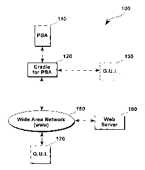
Refernng now to Figure 1, a block diagram of one embodiment for a network
architecture is illustrated. In this embodiment, portable sports appliance
(PSA) 110 is
coupled to cradle 120. PSA 110 may be used to monitor and store physical and
biometrical parameters of its user. In this embodiment, PSA l I0 is a portable
device.
However, it will be recognized by one of ordinary skill in the art that a
stationary device
or a device included in some other device or equipment may be used with this
invention
without loss of generality. PSA 100 may be used by any person. For example,
PSA 100
may be used by a person engaged in fitness activity, a professional athlete
during
exercise, or an employee wishing to know how his stress level changes during
the day.
The operation of PSA 110 and its functions will be described in more details
below.
Cradle 120 is used to upload data from personal data capture device 100 to
network I50. In one embodiment, cradle I20 may resemble a support element for
a
telephone receiver or handset. Cradle 120 may include a modem to transmit data
over
CA 02366957 2001-09-04
WO 01/49169 PCT/US00/35015
telephone lines and may be configured to provide two-way connection to wide
area
network 150. In one embodiment, placing personal data capture device 110 in
cradle
120 may trigger an automatic dialing of a telephone number of server 160. When
the
telephone line is free, data from personal data capture device 110 may then be
transmitted to server 160 through wide area network 150.
Alternatively, the data may be transmitted from personal data capture device
to
server 160 using a wireless transmitter. That is, cradle 120 is not used, and
the data is
transmitted over a wireless carrier. It should be understood by one of
ordinary skill in
the art that various ways of transmitting data from PSA 110 to server 160,
other than
those described above, may be used with this invention without loss of
generality.
Cradle 120 may be used with more than one PSA 110. For example, if each
family member has his or her own PSA 100, cradle 120 may be shared by all
family
members. Personal data of each family member is then uploaded to server.160 at
various
points of time. Sever 160 may receive personal data from numerous PSA users.
This
personal data may then be processed by third parties that may provide feedback
information to those PSA users who subscribe for this service.
In one embodiment, server 160 is coupled to wide area network 150. Wide area
network 150 may include, for example, the Internet, America On-Line,
CompuServe, Microsoft Network ~, or Prodigy TM. In addition, wide area network
150 may include, for example, conventional network backbones, long-haul
telephone
lines, Internet service providers, or various levels of network routers. Using
conventional network protocols, server 160 may communicate through wide area
network 150 to a plurality of clients:
In one embodiment, server communicates to clients 130 and 170. Clients 130
and 170 represent any device that may enable user's access to data. For
simplicity,
Figure 1 shows only two clients, client 130 and client 170, that can
communicate to
server 160. However, it will be recognized by one of ordinary skill in the art
that server
160 may communicate to a various number of clients and that a wide variety of
client
devices may be used with this invention without loss of generality. Such
devices may
include, for example, a conventional computer system, a network computer or
thin client
device (e.g., WebTV Networks Internet terminal or Oracles NC), a laptop or
palm-
top computing device (e.g., Palm Pilots), a digital consumer device (e.g., a
digital TV, a
digital camcorder, or a "kitchen" computer"), etc. In one embodiment, clients
130 and
6
CA 02366957 2001-09-04
WO 01/49169 PCT/US00/35015
170 may have a Graphical User Interface (GUI) to allow users to access data. A
GUI is a
graphics-based user interface that incorporates icons, pull-down menus and a
mouse.
GUIs may include, for example, Microsoft Windows, Apple Macintosh, UNIX Motif,
or
UNIX OPENLOOK.
Clients 130 and 170 may be connected to server 160 in various ways. In one
embodiment, clients 130 and 170 may be connected to server 160 through wide
area
network 150. Client 170 may represent client devices of third parties, e.g.,
health and
fitness specialists, who access personal data of subscribers on server 160 via
wide area
network 150 to generate feedback information to subscribers. Client 130 may
represent
client devices of subscribers who access the generated feedback information
via wide
area network 150. In this embodiment, client 130 is connected to cradle 120
which
provides two-way connection with wide area network 150. However,. it will be
understood by one of ordinary skill in the art that client 130 does not need
to be
connected to cradle 120. Instead, client 130 may use the same connection means
as
client 170.
In an alternate embodiment (not shown in Figure I), a client, such as client
130
or client 170, may be directly connected to server 160 or through a modem in a
conventional way. When connected to wide area network 150, clients 130 and 170
may
be connected directly to wide-area network 150 through direct or dial up
telephone or
other network transmission line. Alternatively, clients 130 and 170 may be
connected to
wide-area network 150 using a modem pool. A conventional modem pool may allow
a
plurality of clients to connect with a smaller set of modems in modem pool for
connection to wide-area network 150. In yet another network typology, wide-
area
network 150 may be connected to a gateway computer, which may be used to route
data
to clients through a local area network. In this manner, clients can
communicate with
each other through a local area network (LAN) or with server 160 through a
gateway and
wide-area network 150. Alternatively, LAN may be directly connected to server
I60 and
clients may be connected through LAN. For example, subscribers' personal data
may be
processed by a company employing fitness instructors, athletic trainers,
physicians and
other heath and fitness specialists. Such a company may use LAN topology for
providing internal communication between its employees. LAN may then be
connected
to server 160 through wide area network 150 for allowing communication between
subscribers and health and fitness specialists.
7
CA 02366957 2001-09-04
WO 01/49169 PCT/US00/35015
Using one of a variety of network connection means, server computer 160 may
comniunicate with clients 150 using conventional means. In one embodiment, a
server
computer 160 may operate as a web server if the World-Wide Web (WWW) portion
of
the Inr:ernet is used for wide area network 150. Using the HTTP protocol and
the HTML
coding language across a network, web server I60 may communicate across the
World-
wide Web with clients 130 and 170. In this configuration, clients 130 and 170
may use
a client application program known as a web browser such as the Netscape~''M
Navigators published by Netscape Corporation of Mountain View, CA, the
Internet
Explorers published by Microsoft Corporation of Redmond, Washington, the user
interface of America On-Line, or the web browser or HTML translator of any
other
conventional supplier. Using such conventional browsers and the World-Wide
Web,
clients 130 and 170 may access graphical and textual data or video, audio, or
tactile data
provided by web server 160. Conventional means exist by which clients 130 and
170
may supply information to web server I60 through the World-Wide Web 150 and
the
web server 160 may return processed data to clients 130 and 170.
Having briefly described one embodiment of the network environment in which
the present invention operates, Figure 2 illustrates an example of a computer
system 200
illustrating an exemplary client 130 or 170, or server 160 computer system in
which the
features of the present invention may be implemented. Refernng to Figure 2,
computer
system 200 is comprised of a bus or other communications means 201 for
communicating information, and a processing means such as processor 202
coupled with
bus 201 for processing information. Computer system 200 further comprises a
random
access memory (RAM) or other dynamic storage device 204 (commonly referred to
as
main memory), coupled to bus 201 for storing information and instructions to
be
executed by processor 202. Main memory 204 also may be used for storing
temporary
variables or other intermediate information during execution of instructions
by processor
202. Computer system 200 also comprises a read only memory (ROM) and /or other
static storage device 206 coupled to bus 201 for storing static information
and
instructions for processor 202.
An optional data storage device 207 such as a magnetic disk or optical disk
and
its corresponding drive may also be coupled to computer system 200 for storing
information arid instructions. Computer system 200 can also be coupled via bus
201 to a
display device 221, such as a cathode ray tube (CRT) or a liduid crystal
display (LCD),
8
CA 02366957 2001-09-04
WO 01/49169 PCT/US00/35015
for displaying information to a computer user. For example, graphical or
textual
information may be presented to the user on display device 221. Typically, an
alphanumeric input device 222, including alphanumeric and other keys is
coupled to bus
201 for communicating information and/or command selections to processor 202.
Another type of user input device is cursor control device 223, such as a
conventional
mouse, touch mouse, trackball, or other type of cursor direction keys for
communicating
direction information and command selection to processor 202 and for
controlling cursor
movement on display 221. A fully-loaded computer may optionally include video,
camera, speakers, sound card, and many other conventional options.
Alternatively, clients 130 and 170 can be implemented as any device described
above. Such a device does not necessarily include all of the elements and
features of the
above-described exemplary computer system; however, the functionality of the
present
invention may nevertheless be implemented with such devices.
A communication device 225 is also coupled to bus 201 for accessing remote
computers or servers, such as web server 160, or other servers via the
Internet, for
example. The communication device 225 may include a modem, a network interface
card, or other well known interface devices, such as those used for
interfacing with
Ethernet, Token-ring, or other types of netwo>:ks. In any event, in this
manner, the
computer system 200 may be coupled to a number of servers 160 via a network
infrastructure such as the infrastructure illustrated in Figure 1 and
described above.
Figure 3 is a flow diagram of one embodiment for managing data of subscribers
via a network. At processing block 304, personal data of a subscriber is
captured in a
personal data capture device. The personal data includes physical and
biometrical
parameters of the subscriber. These parameters may be measured at any time and
during
any activity of the subscriber, including, for example, physical exercise,
work related
activities, or quiet time at home. The process of measuring the parameters and
capturing
them in the personal data capture device will be described in more detail
below.
At processing block 304, the personal data is transmitted from the personal
data
capture device to a network server. In one embodiment, the personal data may
be
transmitted using a cradle. That is, the personal data capture device is
placed in the
cradle which triggers an automatic dialing of a telephone number of the
server. When
the telephone line is free, data from the personal data capture device may be
transmitted
to the web server through a wide area network. The transmitted data may
include a
9
CA 02366957 2001-09-04
WO 01/49169 PCT/US00/35015
unique identifier associated with the data capture device. Alternatively, the
cradle may
not be used, and the personal data may be transmitted to the v>~eb server
using a wireless
transmitter via a wireless corner.
The server stores personal data of subscribers. In one embodiment, each
subscriber is required to have an account registered at the web server in
order to receive
services provided by the web server. The account may need to be created before
personal data is first transmitted to the web server. In alternate
embodiments, the
account may be created when the personal data capture device is purchased or
at the time
of first transmission of personal data to the web server.
At processing block 30~, the personal data is analyzed to generate feedback
information. In one embodiment, the personal data on the web server may be
accessed
by a third party. The third party may include, for example, a fitness
instructor, an
athletic trainer, a diet or nutrition specialist, a physician, or any other
fitness or health
specialist. One or more specialists may have access to the personal data of
the subscriber
depending on the subscriber's needs and subscribed services. Every specialist
involved
in the subscribed services may create feedback information based on the
personal data of
the subscriber.
At processing block 3I0, the feedback information is presented to the
subscriber
over a wide area network. In one embodiment, the subscriber accesses the
feedback
information upon entering a password. The password may be associated with the
subscriber's account. Alternatively, the subscriber may need to enter a code
associated
with the personal data capture device or any other unique information allowing
to
prevent access to the subscriber's personal data by outsiders. It will be
understood by
one of ordinary skill in the art that various other ways of maintaining
confidentiality of
the subscriber's personal data may be used with the present invention without
loss of
generality.
In one embodiment, the feedback information is posted on a private web site of
the subscriber. Alternatively, the subscriber may access the feedback
information on a
particular web site known to all subscribers (e.g., /www.sportbrain.com/) upon
entering a
password or a certain unique code. In addition to the feedback information,
the personal
data may be presented to the subscriber in numerous forms. The numerous forms
may
include, for example, various graphs, tables, map overlays, progressive
charts, and
comparisons with data of other subscribers.
CA 02366957 2001-09-04
WO 01/49169 PCT/US00/35015
In one embodiment, the personal data capture device may be configured from the
web site by the subscriber. Alternatively, the personal data capture device
may be
configured by a health or fitness specialist over the wide area network. For
example, a
fitness instructor may decide to reconfigure the personal data capture device
according to
a new version of the exercise program that the instructor designed for the
subscriber
based on the recent personal data of the subscriber. In yet another
embodiment, both the
subscriber and the instructor may have the ability to reconfigure the personal
data
capture device over the network.
The personal data capture device will now be described in more detail. Figure
4
is a block diagram of one embodiment for a personal data capture device.
Refernng to
Figure 4, personal data capture device 400 includes microprocessor 460 which
is coupled
to memory 480, software program 482 and electronics 484. In one embodiment,
personal data capture device 400 is a portable device. In this embodiment,
personal data
capture device 400 may be clipped to the user's waist band, or may be secured
to the user
in other ways such as via a wrist watch-type arrangement or by simply being
held by the
user. In alternate embodiments, personal data capture device 400 may be a
stationary
device or a device included in some other device or equipment.
In one embodiment, personal data capture device 400 includes a global
positioning system (GPS) signal receiver 430 which receives GPS signals 410.
GPS
signals 410 may include three-dimensional positional information and velocity
of the
user when the user is walking or running, or is engaged in some other relevant
activity.
Personal data capture device 400 may also include a motion sensor 450 which
may
improve the accuracy of the above information or substitute it when GPS signal
410 is
interrupted. In addition, personal data capture device 400 may include heart
rate receiver
430 which receives heart beat rate from wireless heart rate transmitter 420.
Various
other sources may provide signals to personal data capture device 400.
Personal
parameter transmitter 405 represents a wide variety of signals that may be
received by
various personal parameter receivers 425 included in personal data capture
device 400.
For example, a bathroom weight scale may have a transmitter built in it to
automatically
transmit signals with weight data to personal data capture device 400. A blood
pressure
meter, a glucose meter, exercise equipment such as treadmills and stationary
bikes, or
any other device or equipment can transmit data to personal data capturing
device 400
which will receive it using a corresponding personal parameter receiver 425.
In one
11
CA 02366957 2001-09-04
WO 01/49169 PCT/US00/35015
embodiment, heart rate rer:,eiver 440 is personal parameter receiver 425. It
will be
understood by one of ordii°~ary skill in the art that all of the
receivers described above or
any combination of them may be included in personal data capture device 400
without
loss of generality.
Upon receiving a signal, any of the receivers 42S through 450 outputs data to
microprocessor 460. Microprocessor 460 stores this data in memory 480. In one
embodiment, personal data capture device may include electronic beeper 470 for
providing audio signals related to the personal data. For example, when
personal data
capture device 400 is configured over the network as described above,
electronic beeper
470 can be set to signal low and high heart rate target limits, low and high
pace limits,
low and high weight limits, etc. Alternatively, or in addition to electronic
beeper 470,
personal data capture device 400 may include digital audio 472 to provide more
detailed
feedback. Digital audio 472 may be configured to provide various real time
information
(e.g., distance average speed) related to personal parameters transmitted to
personal data
capture device 400. Personal data capture device 400 may also include digital
audio
player such as MP3 player 474 to play digital recordings. In one embodiment,
the real
time information generated by digital audio 472 andlor digital recordings
played by MP3
player may be communicated to the user by earphone 476 coupled to digital
audio 472
and/or MP3 player 474. It will be understood by one of ordinary skill in the
art that any
combination of personal data receivers 425 through 450 and audio signal
generators 470
through 476 may be used with personal data capture device 400 without loss of
generality.
In one embodiment, microprocessor 460 is coupled to modem 490 which is
contained in a cradle. Modem 490 provides a direct two-way connection to web
server
160 and subscriber's web site 492 over a wide area network. In this
embodiment, when
personal data capture device 400 is placed in the cradle, modem 490
automatically dials
a phone number of web server 160. When the phone line is free, software 482
causes
microprocessor 460 to upload subscriber's personal data from memory 480 to web
server
160. Alternatively, personal data capture device may include a wireless
transmitter (not
shown) which may be used by microprocessor 460 to transmit the subscriber's
personal
data from memory 480 to web server 160 via a wireless Garner.
In one embodiment, the subscriber's personal data may be posted on
subscriber's
web site 492. Alternatively, web site 492 may be a company web site which can
be
I2
CA 02366957 2001-09-04
WO 01/49169 PCT/US00/35015
accessed by all subscribers. GUI 494 is coupled to wPb site 492 to provide the
user with
a convenient way to view the data.
In one embodiment, the user may be.provided with an option of adding new
features to personal data capture device 400 over the °~Nide area
network. For example,
the user may be notified of availability of a new or improved version for
personal data
capture device 400. The user may then be allowed to download the new or
improved
version directly over the Internet.
Figure 5 is a block diagram of another embodiment for a personal data capture
device. Refernng to Figure 5, personal data capture device 500 may include the
same
features and functionality as personal data capture device 400. In one
embodiment,
personal data capture device 500 includes all data receivers 425 through 450
and all
audio signal generators 470 through 476. In alternate embodiments, personal
data
capture device 500 may include any combination of receivers 425 - 450 and
audio signal
generators 470 - 476.
In one embodiment, panic button 486 is coupled to microprocessor 460. In this
embodiment, software 482 analyzes personal data in memory 480. If the personal
data
includes a parameter that is below or exceeds a certain panic parameter (e.g.,
heart rate is
too low or too high), software 482 may cause microprocessor 460 to invoke
panic button
486. Panic button 486 may then produce a panic signal to a satellite page
service or a
cellular service 422. In one embodiment, the panic parameters may be set or
updated
from the user's web site 492 and transferred to memory 480 over the wide area
network.
In alternate embodiments, the panic parameters may be set or updated by health
or
fitness specialists in web server 160 or programmed during the manufacture of
personal
data capture device 500.
In one embodiment, GPS receiver 496 is coupled to modem 490. GPS receiver
496 receives signals directly from GPS 410 to provide differential correction
of GPS
signals. Alternatively, differential correction of GPS signals may be done
from a
personal web site of a subscriber or from a company web site.
Figure 6 is a flow diagram of one embodiment for monitoring data of
subscribers
using a personal data capture device. Refernng to Figure 6, at processing
block 604,
personal data is received by personal parameter receivers. As described above,
the
personal data may be received from one or more sources. Personal parameter
receivers
may include, for example, a GPS signal receiver, a heart rate receiver, a
motion sensor, a
13
CA 02366957 2001-09-04
WO 01/49169 PCT/US00/35015
weight data receiver, a blood pressure receiver, a glucose measurement
receiver, or an
exercise data receiver.
At processing block 606, the personal data is stored in the personal data
capture
device. The personal parameter receivers output the personal data to
microprocessor 460
which stores the personal data in memory 480 of the personal data capture
device. The
personal data may include a timestamp and information identifying a source of
a
personal parameter. In one embodiment, when the personal data includes certain
parameters, an audio signal may be produced by electronic beeper 470. In
addition,
certain real time information may be communicated to the user by digital audio
472 and
earphone 476 based upon the personal data. Alternatively or in addition to the
above
audio signals, when the personal data includes a panic parameter, a panic
signal may be
generated to a satellite page service or a cellular service.
At processing block 608, the personal data is transmitted from memory 480 to
the
web server via the wide area network. In one embodiment, the personal data may
be
transmitted over a phone Iine using cradle 120 which may have a direct two-way
connection to the Internet. Alternatively, the personal data may be
transmitted from the
personal data capture device to the web server using a wireless transmitter
via a wireless
carrier. The personal data may then be posted on the subscriber's web site.
Figure 7 is a flow diagram of one embodiment for posting personal data of a
subscriber on a web site. Referring to Figure 7, at processing block 704, web
server 160
receives personal data of subscribers. In one embodiment, the personal data
may be
received from a plurality of personal data capture devices. The personal data
may
comprise physical data and biometrical parameters of each subscriber. The
personal data
may be stored in a repository of personal data which resides either directly
on web server
160 or on a separate computer accessible by web server 160.
In one embodiment, the personal data of the subscriber is stored in the
repository
of personal data only if the subscriber maintains an account registered with
web server
160. The account may be registered at any time before or simultaneously with
first
transmission of subscriber's personal data. At the time of creating the
account, the
subscriber may be required to provide a password or a code to prevent access
to the
personal data by anyone other than the subscriber. In one embodiment, the
account
information may be stored together with the personal data in the repository of
the
14
CA 02366957 2001-09-04
WO 01/49169 PCT/US00/35015
personal data. Alternatively, the account information may be stored in a
separate
database or file.
At processing block 706, the personal data is processed to create feedback
information. Det~ending on the services selected by the subscriber, various
feedback
information may be created in response to the subscriber's personal data. In
one
embodiment, a fitness instructor, an athletic trainer, a diet or nutrition
specialist, a
physician, or any other fitness or health specialist may be able to access the
subscriber's
personal data. One or more fitness or health specialists may analyze the
personal data
and create the feedback information. In alternate embodiments, the personal
data or its
portion may be analyzed by a software program which may either create the
feedback
information entirely or assist fitness or health specialists in creating the
feedback
information. The feedback information may be stored either in the repository
of personal
data or in a separate database residing on web server 160 or on a different
computer
accessible by web server 160.
At processing block 70~, the feedback information is posted on a web site. As
described above, the web site may be a personal web site of the subscriber or
a company
web site that can be accessed by all subscribers. In one embodiment, the
personal data
may be posted on the web site in various forms such as graphs, tables and map
overlays.
In addition, the subscriber's personal data may be compared with personal data
of other
subscribers or with this subscriber's history data. In one embodiment, when
the personal
web site is used, the web site may be specifically created as a part of
services provided to
the subscriber. Alternatively, the subscriber's existing web site may be used
for posting
the feedback information and the personal data of the subscriber. In yet
another
embodiment, the feedback information and personal data may be posted on a
company
web site known to all subscribers. In either embodiment, access to the
feedback
information and personal data is protected either by a password or other means
for
maintaining confidentiality of personal information.
Several variations in the implementation of the method and system for
monitoring personal data of subscribers via a wide area network have been
described.
The specific arrangements and methods described here are illustrative of the
principles of
this invention. Numerous modifications in form and detail may be made by those
skilled
in the art without departing from the true spirit and scope of the invention.
Although this
CA 02366957 2001-09-04
WO 01/49169 PCT/US00/35015
invention has been shown in relation to a particular embodiment, it should not
be
considered so limited. Rather it is limited only by the appended claims.
16