Note : Les descriptions sont présentées dans la langue officielle dans laquelle elles ont été soumises.
CA 02367019 2001-09-05
WO 00/54902 PCT/SEOO/00548
Tool for automatic roll folding
TECHNICAL FIELD
The present invention relates to a folding tool for automatic roll folding,
and
comprises a first member fixed to a manipulator, a second member movably
connected to the first member and including a first folding roller, and a
spring disposed to permit a relative movement between the first member
and the second member, under the action of a force increased by the
movement.
The present invention also relates to a method of roll folding by means of a
folding tool which comprises a fixed first member at a manipulator and a
second member movably connected to the first part and having a folding
roller, the member being urged away from the first member by a spring force
directed away from the first member.
Finally, the present invention also relates to the use of the above-outlined
folding tool and the reduction into practice of the above-outlined method.
BACKGROUND ART
In the joining together of two sheet metal parts in such contexts where the
requirements on surface finish are high, folding is often employed as a better
alternative to welding. The folding process is such that one of the workpieces
is given an edge portion projecting out over the second workpiece, the edge
portion being folded in over the second workpiece and urged against it such
that the edge of the second workpiece will be accommodated between the
first workpiece and its folded-over edge portion. For the above-mentioned
folding over of the edge portion of the first workpiece, use is generally made
of a roller which is displaced in the longitudinal direction of the edge
portion.
CA 02367019 2001-09-05
WO 00/54902 2 PCT/SEOO/00548
EP 577 876 discloses a folding apparatus mounted on an industrial robot. The
apparatus described in this publication has a first guide member which is
immovably secured in the movement devices of the robot, and a second
guide member which is accommodated in and displaceably guided in a
recess in the first guide member. The two guide members thereby together
form a telescope arrangement. Between the two mutually movable guide
members, a spring is disposed which affects the movements between the
guide members and is directed to counteract movement of the guide
members towards one another. The above-described construction makes for
the movement of the folding roller from and towards the movement devices
of the robot which is necessary for an adequate folding result. However, the
precision in the movements of the folding roller is far too poor because of
the
selected formation of the guide.
In the above-outlined construction, the folding roller is also located a
considerable distance laterally outside the longitudinal direction of the
telescope arrangement, which coincides with the direction of movement of
the second guide member. Hereby, the guide member will be obliquely
loaded so that a "jammed drawer effect" may be feared. Such an oblique
loading destroys the precision in the movements, since the smallest play in
the telescopic guide because of the large lateral projection of the folding
roller gives large movements in the folding roller. In addition, a
considerably
harder wear on the mutually movable components may be feared than
would otherwise be the case.
The prior art apparatus has only a single folding roller, for which reason
time-consuming readjustment work or retooling will be the result.
ACCOUNT OF THE PRESENT INVENTION
The present invention has for its object to design the folding tool intimated
by way of introduction such that it obviates the drawbacks inherent in prior
art technology. In particular, the present invention has for its object to
design
CA 02367019 2001-09-05
WO 00/54902 3 PCT/SE00/00548
the folding tool in such a manner that the folding roller will have a guiding
with considerably higher precision than that which can be achieved
employed prior art technology. Further, the present invention has for its
object to realise a folding tool which is not subjected to oblique loadings
which may destroy the service life or affect the movement pattern of the
folding roller. Finally, the present invention also has for its object to
realise a
folding tool which is extremely robust and operationally reliable when in
use.
The objects forming the basis of the present invention will be attained if the
folding tool intimated by way of introduction is characterized in that the
second member is rotatably connected to the first member.
In that the second member with the folding roller in principle executes a
pendulum motion, its guiding can be made with considerably greater
precision than is the case in a telescope arrangement with a folding roller
projecting considerably in the lateral direction. Further, tendencies for
oblique loading will be eliminated or reduced as a result of this
construction.
Another object of the present invention is further to improve the precision of
the folding tool.
According to the present invention, this is attained in that the folding tool
includes a support roller and a plane roller, the support roller having a
diameter which is greater than that of the plane roller, and the rollers being
disposed to freely rotate about the same axis.
As a result of these features, the advantage will be afforded that the
precision
of the folding will not only be dependent on the accuracy of the movement
pattern of the manipulator and the precision of the folding tool, but may be
further improved by the abutment of the support roller against the
workpiece or that surface on which it rests.
CA 02367019 2001-09-05
WO 00/54902 4 PCT/SEOO/00548
A further improvement of the precision of the folding, in particular in the
lateral direction (sideways) will be achieved if a guide roller is employed
during the final compression of the union, the so-called final folding. This
guide roller is disposed to abut against a guide path which may be an
integral part of the bed on which the workpiece rests. The axes of the guide
roller and the folding roller intersect one another substantially at a right
angle. As a result, the abutment pressure of each respective roller can be
adjusted independently. It is thus possible to affect the abutment pressure of
the folding roller against the workpiece without actuation.
Furthermore, the present invention has for its object to improve the
flexibility
and production capacity of the apparatus according to the present invention.
This object is attained if the folding tool includes a second folding roller
which is rotary about an axis separate from the axis of the first roller.
As a result of these features, the advantage will be afforded that the folding
tool need only be given new orientation in relation to the workpiece before a
new working phase is commenced.
Finally, the present invention has for its object to realise the possibility
of
varying the spring constant in the spring which is included in the folding
tool.
This object is attained in that the spring comprises a gas spring which has an
expandable bellows containing a gas.
As a result, the possibility will be afforded of rapidly varying the force
with
which the folding tool abuts against the workpiece.
CA 02367019 2001-09-05
WO 00/54902 5 PCT/SE00/00548
BRIEF DESCRIPTION OF THE ACCOMPANY DRAWINGS
The present invention will now be described in greater detail hereinbelow,
with reference to the accompanying Drawings. In the accompanying
Drawings:
Fig. 1 is a perspective view of the apparatus according to the present
invention;
Fig. 2 shows the apparatus according to the present invention seen in the
direction of the arrow A in Fig. 1;
Fig. 3 is a side elevation in the direction of the arrow B in Fig. 1;
Fig. 4 is an exploded diagram of the apparatus according to the present
invention;
Fig. 5 is an exploded diagram, on a larger scale, of the components of the
apparatus carrying the folding roller.
Fig. 6 shows a first modified embodiment of the apparatus according to the
invention, seen in the direction of the arrow A in Fig. 1;
Fig. 7 is a view corresponding to that of Fig. 3 of a second modified
embodiment of the apparatus according to the present invention;
Fig. 8 is a view corresponding to that of Fig. 3 of a third modified
embodiment of the apparatus according to the present invention; and
Fig. 9 is a view corresponding to that of Fig. 6 of a fourth modified
embodiment of the apparatus according to the present invention.
CA 02367019 2001-09-05
WO 00/54902 6 PCT/SE00/00548
DESCRIPTION OF PREFERRED EMBODIMENT
The present invention will be described hereinbelow by way of example as
applied in an industrial robot. Naturally however, it can be applied in any
other type of movement apparatus or manipulator which can create the
requisite relative movement pattern between a workpiece and a folding tool,
which in practice includes a folding roller which abuts against and rolls
along the workpiece. The term 'manipulator' should thus be interpreted so
broadly that it also encompasses an apparatus which displaces a workpiece
in relation to a fixedly disposed folding tool, as well as apparatuses in
which
both the workpiece and the folding tool move.
On folding, the workpieces rest on a support bed 28 (intimated only in Fig.
9), which partly serves the function of defining the form of the finished
fold,
and partly functions as an abutment surface for the workpieces when these,
during the final phase of the folding operation, are processes by a folding
roller.
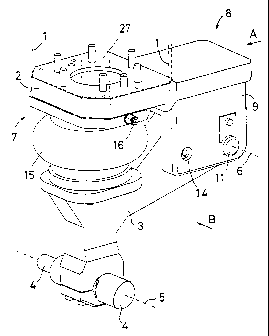
In Fig. 1, broken lines intimate a movement apparatus or a manipulator
included in an industrial robot, the manipulator being that section of the
industrial robot which is movable along extremely complicated movement
patterns and which serves for securing such end effectors or equipment as
the robot is to handle. Reference numerals 2 and 3 relate to first and second
support members, respectively, support members in which the first or upper
support member 2 is secured in the manipulator 1 of the robot by means of
suitable bolt unions and associated guide surfaces. The second or lower
support member 3 supports on either side a folding roller 4 which is
rotatably journalled in relation to the second support member which is
rotatable about a common first shaft or axis 5. The folding rollers 4 are
intended to be in contact with and urge against an edge portion of the
workpiece which is to be folded, i.e. move along a folding path. Interchange
between the two folding rollers may take place by rotating the apparatus
CA 02367019 2001-09-05
WO 00/54902 7 PCT/SEOO/00548
according to the present invention about a vertical axis 24 (Fig. 3), e.g. by
movement in the robot.
The second support member 3 is movable in relation to the first support
member 2 and is in particular pivotal in relation to it about a second axis 6
which is located a distance from the first axis 5 and the anchorage of the
support member 2 in the manipulator and which, in the illustrated
embodiment, is parallel with the first axis 5. This implies that the second
support member 3 can execute a pendulum pivotal motion about the second
axis 6, whereby the distance between the first axis 5 and the folding roller
4,
on the one hand, and the manipulator 1 of the robot on the other hand is
changeable as a result of this pivotal movement.
When the apparatus according to the present invention is in operation, it is
displaced along a folding path, i.e. along an edge portion of a workpiece
which is resting or fixedly clamped on a support bed 28 (Fig. 9) under the
action of the manipulator 1 in a direction which is substantially at right
angles to the axis 5. Other angles may also occur. As a result of the pivotal
mobility of the folding roller 4 towards and away from the manipulator 1,
the folding roller will also be movable in a direction which intersects the
plane defined by the first axis 5 and the movement of the folding roller 4
along the folding path. As a result, the folding roller 4 is movable towards
and away from the folding path, i.e. the workpiece, under the action of the
pivotal movements of the second support member 3 in relation to the first
support member 2.
The axes 5 and 6 are, in the currently described embodiment as intimated
above, substantially parallel with one another but are located in spaced apart
relationship. In order to achieve this, the lower or second support member 3
is approximately in the form of an L, where the folding roller 4 is disposed
in
the region of the free end of the shorter shank, while the second axis 6 is
disposed in the region of the free end of the longer shank.
CA 02367019 2001-09-05
WO 00/54902 8 PCT/SEOO/00548
The first support member 2, i.e. the support member secured in the
manipulator 1, is elongate, flat-shaped and has a first end portion 7 with an
upwardly facing surface 27 in abutment against the manipulator 1, the
support member 2 being positionally fixed in the manipulator 1 by means of
the above-mentioned bolt union and suitable guide surfaces. The opposite,
second end portion 8 of the first support member 2 is located in the region of
the second shaft 6. The second end portion 8 of the support member has, on
its side facing away from the manipulator 1, two mutually parallel lugs 9 and
between which the longer shank of the second support member 3 is
10 accommodated and guided so that all movements than the above-mentioned
pivotal or pendulum movement are prevented. The pivotal or rotary
connection between the two support members is achieved by means of a
journal pin 11 which extends through both of the lugs 9 and 10, and also an
aperture provided with a bushing in the second or lower support member 3.
Between the inside of the two lugs 9 and 10 and the side surfaces of the
second support member 3, there are disposed journal washers 12 and 13 so
that the second or lower support member 3 will be accurately guided in
relation to the first support member 2 both in the axial direction of the
journal pin 11 and radially in relation to this journal pin.
In order to restrict the pivotal capability of the lower support member 3,
this
has an elongate and arcuate curved aperture (not shown on the Drawings)
around the second axis 6 through which a locking pin 14 extends. The
locking pin 14 is secured in both of the lugs 9 and 10.
As was mentioned above, the folding roller 4 is movable towards and away
from the manipulator 1 of the robot in a direction which bisects that plane
which is defined by the first axis 5 and the movement direction of the folding
roller 4 along the folding path. This movement of the folding roller 4 towards
and away from the manipulator 1 and towards and away from the folding
path, i.e. the workpiece, is influenced by spring means which includes an
inner bellows 15 actuable by a gaseous pressure medium. The bellows 15 has
an inlet 16 for the above mentioned pressure medium which is in flow
CA 02367019 2001-09-05
WO 00/54902 9 PCT/SEOO/00548
communication with an apparatus for rapid supply of or evacuation of the
gaseous pressure medium. Hereby, the spring constant of the spring 15 may
rapidly be modified. On pressurising the interior of the bellows 15, there
will
be realised a spring force which strives to displace the folding roller 4 in a
direction away from the manipulator, i.e. towards the workpiece. If the
manipulator 1 is seen as fixedly clamped in relation to the folding path, a
change to the inner pressure in the bellows 15 will also imply a change of the
force with which the folding roller 4 abuts against the workpiece. As is
apparent from the Drawings, the bellows 15 is placed between the two
support members 2 and 3 and, in particular, in the region of the end portion
7 of the first support member 2 co-operating with the manipulator 1.
Fig. 5 shows the securement of the folding roller 4 in the lower end of the
second or lower support member 3. It will be apparent from the Drawing
that the support member has a lower bearing cover 17 which is securable in
the support member by means of screws 18. Both the bearing cover and the
lower end of the lower support member 3 have seats 19 for accommodating
and fixedly locking rolling bearings 20. The rolling bearings 20 accommodate
a stub shaft 21 which, at opposite ends, has threaded bores in which the
folding rollers 4 may be screwed in place. (The folding rollers illustrated in
Fig. 5 differ from those illustrated in Figs. 1-3 and thereby demonstrate how
the folding rollers are readily interchangeable). In order to facilitate
screwing
in place of the folding rollers, these - and also the stub shaft 21 - have
keyways 22.
Fig. 6 shows a modified embodiment of the apparatus according to the
present invention. In this embodiment, the axis 5 (or a counterpart thereto)
carries a folding roller 4 which includes a support roller 23a and a plane
roller 26a. Suitably however, it may have two plane rollers 26a and 26b and
two support rollers 23a and 23b, one support roller and one plane roller
being disposed at each one of the opposite end portions of the axis or shaft
5.
As is apparent from the Drawing, the support rollers are of greater diameter
than their respective plane rollers and are intended to roll and support
CA 02367019 2001-09-05
WO 00/54902 10 PCT/SEOO/00548
against the workpiece or the support bed 28 on which is rests. Further, all
rollers are individually rotary about their axis.
A variation of this embodiment is intimated in Fig. 6 by the broken line 5"',
which implies that the axis of rotation 5"' of the rollers 4a, 4b, 23a and 23b
still lies in the same plane as the original axis 5 but at an angle with it.
In the foregoing, the shaft 5 supporting the roller or rollers (both the guide
and folding rollers) has been described as parallel with the pivot axis 6 of
the
second support member 3. In alternative embodiments, this is not necessary
or desirable. Hence, the shaft 5, or more correctly its counterpart as
intimated
above, may have optional orientation about a vertical axis 24 which is shown
in Figs. 3 and 6 and which may be a normal to the upper surface 27 of the
first support member 2 which abuts against the manipulator 1 of the robot.
Further, it is possible to give a counterpart 5', 5" and 5"' to the shaft or
axis 5
optional orientation about a recumbent axis 25 which is shown in Fig. 3 and
which is at right angles to the vertical axis 24. Examples of such various
alignments of the shaft or axis carrying the roller or rollers are shown in
Figs.
6, 7 and 8 at 5, 5" and 5"'.
The present invention also includes the embodiment in which the part of the
lower support member 3 carrying the roller or rollers (both guide rollers and
folding rollers) has more than one shaft for supporting one or more rollers
each. These shafts may have all of the above-indicated orientations and may
be parallel with one another or make an angle with one another.
Fig. 9 shows yet a further embodiment of the present invention. In this
embodiment, a guide roller 29 is included which is intended, at least during
the final phase of a folding operation, to guide and improve the precision in
the path of movement of the folding roller 4 by running along a guide path
30 provided for this purpose on the support bed 28.
CA 02367019 2001-09-05
WO 00/54902 11 PCT/SEOO/00548
In the embodiment illustrated in Fig. 9, the guide roller 29 has an axis of
rotation 31 which is substantially at right angles to the axis of rotation 5
of
the folding roller 4 and approximately parallel with the vertical axis 25
illustrated in Fig. 6. However, the orientation of the axis 31 of the guide
roller
29 need not necessarily be as that described above, but must be adapted to
the orientation of the guide path 30 of the support bed 28.
In the embodiment according to Fig. 9, the guide roller 29 may have a
running path with a coating of a resiliently yieldable or elastic material
such
as a plastic or rubber material. Alternatively, such material may be disposed
on the guide path 30.
Finally, the present invention also includes embodiments where the bellows
is replaced or supplemented by other springs, such as saucer springs,
15 helical springs, spiral springs, torsion springs, leaf springs, etc.