Note : Les descriptions sont présentées dans la langue officielle dans laquelle elles ont été soumises.
CA 02367094 2001-09-13
WO 00/57375 PCT/GB00/00920
SECURITY SYSTEMS
The present invention relates to security systems and more particularly to
security systems for protecting electrical or electronic apparatus.
In published European patent application number 675626 the Assignee of the
present invention disclosed a security system for protecting electrical
appliances, in
which appliances fitted with a security module, preferably during manufacture,
were
responsive to the connection of mains electrical power to forward a signal by
way of
the mains electrical connection to a security unit. The security unit was
connected to
both the mains power supply and to a telephone line at the premises. On
receipt of
signalling from an appliance, the security unit established a telephone call
to a remote
operations centre which, based on the calling line identity (CLI) of the
customer's line
returned a security code. The returned security code was then transmitted by
the
domestic security unit to the requesting apparatus which, provided a correct
code
was received, allowed connection of electrical power through to operational
circuits.
If an incorrect code or no code was returned, power to operational circuits
was
denied.
In published PCT patent applicant number GB98/00337 (publication number
W098 36391 ) the Assignee disclosed an improvement to the system the earlier
invention, in which a volatile data store held codes for each of a number of
appliances
whereby only upon first connection of a new appliance or following a mains
failure
would it be necessary to generate a telephone call to the remote operations
centre.
Thus by providing a volatile data store for holing apparatus codes,
application across
the mains supply by a piece of apparatus requesting identity could be
responded to
locally.
Each of the above patent applications relies upon a modern
telecommunications switching network in which CLI is available. It will be
appreciated that some networks are unable to generate CLI and/or do not pass
CLI
across to other networks.
For the avoidance of doubt, the term "security aware apparatus" as used
herein means any energy consuming device including means responsive to an
interruption of power to effect, on reconnection of power, a requirement for
receipt of
signals characterising a locational identity or an apparatus identity and
including
SUBSTITUTE SHEET (RULE 26)
CA 02367094 2001-09-13
WO 00/57375 PCT/GB00/00920
2
means responsive to receipt of signals characterising an incorrect code, or to
the
expiry of a period of time during which no such characterising signals are
received, to
effect temporary inoperability of the device until receipt of signals
characterising a
correct code.
According to the present invention there is provided a security system
comprising a home control unit coupled to receive signals from associated
security
aware apparatus and including communication means to communicate with a remote
operations centre and to receive from the remote operations centre in respect
of the
or each associated security aware apparatus at least one release code to
effect a
response to requesting security aware apparatus, the home control unit
including
means responsive to signals from a global positioning satellite system to
determine its
location and, on communicating with the remote control centre, to forward
signals
characterising the determined location whereby the remote operations centre
determines from the location the or each release code to be transmitted to the
home
control unit.
Preferably the home control unit includes a data store in which release codes
for the or each of the associated security aware apparatus is stored, on first
connection of a security aware apparatus to the system, the home control unit
responding to signals requesting a code transmitted therefrom by communicating
a
respective identity code received from the transmitting apparatus and the
locational
data to the remote operations centre, the remote operations centre returning
at least
one respective code for retransmission to the requesting apparatus.
The data store may be volatile whereby on disconnection of mains electrical
power from the home control unit all stored codes are lost, the home control
unit, on
re-connection of power, communicating with the remote operations centre for
downloading of all data whereby if the home control unit is moved to a
different
location the remote operations centre downloads different release codes or
downloads no codes.
The home control unit may, in addition to transmitting location data to the
remote operations centre, transmit a unit identity code unique to the home
control
unit whereby home control units removed to an unauthorised location may be
traced.
Communication between the home control unit and the remote operations
centre may be by PSTN telephony, radio transmission using direct communication
or
SUBSTITUTE SHEET (RULE 26)
CA 02367094 2001-09-13
WO 00/57375 PCT/GB00/00920
3
by way of low earth orbiting satellite, radio transmission using GSM standards
and
cellular networks or by connectionless communication such as by way of
Internet
communication or electronic mail messaging.
The home control unit may include means to receive signals from security
aware apparatus by data messages superimposed on a mains electrical power
line, by
low power radio communication which may use DECT (digital cordless telephony)
protocols or by connectionless communication. Transmitting means for returning
release codes to security aware apparatus may also use data messages
superimposed
on a mains electrical power line, by low power radio communication or by
connectionless communication using Internet or intranet facilities.
According to a feature of the invention there is provided security aware
apparatus comprising a data store for holding at least one code unique to the
location
of the apparatus, processor means responsive to connection of electrical power
to
cause transmission of signals characterising a code request, transmitting
means for
transmitting the code request and receiving means for receiving a response to
the
code request, the processing means being responsive to an incorrect code or,
if
previously coded, expiry of a predetermined time period without receiving a
code, to
cause temporary inoperability of the apparatus, the transmitting means
including a
low power radio transmitter.
Preferably, the radio transmissions are compatible with DECT protocols and
transmission standards.
The receiving means may comprise a low power radio receiver which may
operate in accordance with DECT protocols and standards.
A security system in accordance with the invention and security aware
apparatus in accordance with the feature of the invention will now be
described by
way of example only with reference to the accompanying drawings of which:
Figure 1 is a schematic representation of at least a part of the security
system;
Figure 2 is a block schematic diagram of a typical security module of
protected apparatus;
Figure 3 shows at least a part of one of the security units of Figure 1 .
Figure 4 is a schematic representation of a data stored by protected
apparatus.
SUBSTITUTE SHEET (RULE 26)
CA 02367094 2001-09-13
WO 00/57375 PCT/GB00/00920
4
Figures 5a to 5e show signalling interchange between the security control
unit of Figure 1 and the appliance and a remote operations centre where a
remote
operations centre is provided;
Figure 6 shows data which may be stored at a remote location or in a home
control unit;
Figure 7 shows data which may be stored in a home control unit responsive
to a remote operations centre;
Figures 8, 9 and 10 is a flow chart showing a process control of the
protected apparatus of Figure 2;
Figures 1 1, 12 and 13 shows part of a flow chart for the processor of a
home control unit of Figure 1 which is responsive to a remote operations
centre;
Figures 14a and 14b show a flow chart of a remote operations centre (where
providedl;
Figure 15 is a schematic diagram showing a number of alternative ways of
communicating between a home control unit and a remote operations centre;
Figure 16 is a block schematic diagram showing various methods of
determining location of a home control unit;
Figure 17 is a schematic diagram of security aware apparatus having a DECT
interface for communicating with a home control unit;
Figure 18 is a schematic diagram showing a part of a home control unit with
a DECT interface for communicating with security aware apparatus of Figure 17;
Figure 19 is a schematic diagram showing a modification to include a TCP/IP
interface for communication by Internet or intranet;
Figure 20 shows an adapted home control unit for use with the apparatus of
Figure 19;
Figure 21 is a block schematic diagram of secure premises having stand
alone security unit;
Figure 22 to 25 are flow charts of the operation of a processor in the
security
unit of Figure 21;
Figures 26A to E are signalling charts showing signalling between the
security unit of Figure 21 and a domestic appliance; and
Figure 27 is a schematic representation of a data store of the security unit
of
Figure 21.
SUBSTITUTE SHEET (RULE 26)
CA 02367094 2001-09-13
WO 00/57375 PCT/GB00/00920
Referring first to Figure 1, the system, previously disclosed, included within
domestic premises 1, the boundary of which is indicated by a dotted line 3, a
home
control unit 2 containing security features for the premises 1 . Various
versions of the
home control unit 2 are described hereinafter, some of which may be "stand
alone"
5 applications but most of which will communicate with a remote security
centre.
The home control unit 2 communicates with security aware electrical
appliances, one of which is indicated at 5. Communication between the home
control
unit and electrical appliance 5 may be in a number of ways, again hereinafter
described, but basically security aware electrical appliance 5 requires a
dedicated
release code to be transmitted to it each time mains electrical power from a
supply
line 6 is disconnected and reconnected. If a security aware electrical
appliance does
not receive its release code then a processor, preferably integrated with
power supply
or other circuitry, prohibits or disconnects electrical supply to operation
circuits of the
apparatus. Thus referring to Figure 2 the electrical appliance 5 is modified
by
incorporating a switch 18 between a power supply 12 of the apparatus and
operational circuits 17. It will be appreciated that the switch 18 is shown
purely for
ease of description and it may be incorporated into the power supply 12. The
apparatus also includes a process control 15, a data store 16 and, in the
particular
version shown here, a frequency shift key interface (FSK) 14 for communicating
across the electrical supply line 6 with a home control unit.
Figure 3 shows the essential components of the home control unit 2, these
being a processor 23, data store 24 and a corresponding FSK communications
interface 25 connected to the supply line 6. basically, as discussed in the
aforementioned published patent application, on connection of an electricity
supply by
way of power input 11 to the apparatus 5, the process control unit 15 consults
the
associated data store 16 to determine whether the apparatus has previously
been
connected in a security aware environment. If it has been so previously
connected
then, referring additionally to Figure 4, an appliance unlock code 26 will be
stored.
the process control therefore causes signalling to be applied to the supply
line 6 by
way of the interface 14, which identifies, for example by use of a
manufacturer
reference, manufacturers equipment reference and electronic serial number, the
specific piece of electrical apparatus which has been connected. The home
control
unit of figure 3 detects the presence of the signalling and via its own FSK
interface
SUBST>rTUTE SHEET (RULE 26)
CA 02367094 2001-09-13
WO 00/57375 PCT/GB00/00920
6
25 compares the received security code with information in its own data store
24
which may be, depending on the type of centre, a volatile store. Having
compared
the equipment serial number with its own data, the processor recovers from its
data
store the appropriate unlock code for the particular appliance and causes this
code to
be transmitted by way of the FSK interface 25 back to the electricity supply
fine 6
and thence through FSK interface 14 to the appliances own processor 15.
Assuming
that the codes are compatible the processor control 15 either now permits
power to
be connected to the operational circuits or, in an alternative mode of
operation, does
not effect power disconnection.
Various features of the security applied to electrical appliances in different
ways and of different home control units will become apparent from the
description
hereinafter. However, which ever kind of communication between security aware
apparatus and a home control unit and/or with a remote security centre is used
the
common feature is that apparatus removed from its authorised location will
cease to
function. Provision is made, as disclosed herein, for legitimate transfer of
ownership
and/or removal of security aware apparatus between premises. Thus only
unauthorised removal of electrical appliances results in failure.
Turning then to Figure 8, we will now consider in brief the manner in which
the security process within a security aware appliance functions. The process
control
unit 15, (Fig 2) which may be integral with the power supply 12 or may be a
part of
the operational circuitry shown at 17, is arranged to determine as hereinafter
described whether power should be supplied or denied to other operational
circuits 17
this capability being generally indicated by switch means 18. It will be
appreciated
that the process for denying power from the switched mode power supply 12
would
not be so simple as a switch 18 which could be easily circumvented and will
actually
be better protected such that in order to overcome the security arrangements
it will
be necessary to replace the entire power supply unit or substantial components
thereof. The process control 15 has access to data held in a data store 16 the
purpose of which will become apparent. The data store 16 is a non-volatile
storage
element capable of holding an appliance identity, the location identity, one
or more
unlocking codes and a blanking code as indicated in Figure 4. Generally
speaking the
location code is a 64 bit code unique to the property in which the appliance
is
SUBSTITUTE SHEET (RULE 26)
CA 02367094 2001-09-13
WO 00/57375 PCT/GB00/00920
7
installed and which is derived from the CLI and by the remote operations
centre of
Figure 1 when a customer subscribes to the service.
The or each unlocking code is a 24 bit code one of which is unique to the
customer premises 3. A further unlock code of 24 bits may be provided in a
more
complex arrangement, the further 24 bit unlock code being unique to the
particular
electrical apparatus 5. Where a unique code for the apparatus 5 is provided
this will
be generated on the first occasion in which the appliance 5 is plugged into
the
electricity supply and will be received in response to a request to the remote
operation centre 4 as hereinafter described or by stand-alone home control
unit.
Throughout the present specification, wherever a stand-alone home control unit
is
provided rather than the more secure arrangement of a remote operation centre
it
may be assumed that the home control processor includes the same functionality
which performs in a similar manner. Where there are substantial differences in
operation these may be specifically considered - for example in one case
providing a
special plug in module for effecting appliance code blanking - or will be
apparent.
The 24 bit blanking code is unique to the appliance and, as in the unique
unlock code, is generated by the remote operations centre 4 in response to
receipt of
a request from the apparatus 5.
The purpose of the codes is firstly to locate the apparatus, that is to say
the
64 bit appliance location code is unique to the home control unit 2 in a
customer
premises 3 and, once a security aware apparatus 5 is aware of its location,
each time
it is connected or disconnected from the mains electricity supply 6 its
process
controller 15 causes FSK interface 14 to transmit the location information and
request an unlock code.
A unique unlock code for the appliance i.e. the 24 bit unlock code (if any)
uniquely provided by the remote operations centre 4 or will be returned by the
home
control unit 2 to the appliance. Note that the home control unit 2 will only
recognise
its own location code. Where only house codes are in use the home control unit
2
will return the 24 bit house unlock code by way of the electricity supply line
and the
FSK interface 14.
If neither the appliance code nor the house code is received by the process
controller 15 then power is denied to the operational circuits. In practice,
power may
be supplied to the operational circuitry for a pre-determined period, say 15
minutes,
SUBSTITUTE SHEET (RULE 26)
CA 02367094 2001-09-13
WO 00/57375 PCT/GB00/00920
8
prior to closing down, to give sufficient time for an appropriate release code
to be
received.
The blanking code, which is unique to an electrical appliance and which is
known only to the particular appliance 5 and to the remote operations centre 4
(except in the case of stand-alone operation) is used to permit the bona fide
transfer
of security aware apparatus between locations or upon sale of the equipment.
Referring to Figure 8, the operation of the process control function of the
security aware apparatus of Figure 2 will now be described. On connection of
power
301 by way of the electricity supply line 6 then a timer "load broadcast
cover" timer
302 is started by process controller 15 which now waits to receive a broadcast
message by way of the FSK interface 14. The purpose of the broadcast timer is
to
cover the eventuality where a major power disruption has resulted in a number
of
security aware appliances in the same customer premises 3 having a
reconnection of
electricity supply at the same time. If a catastrophic domestic electricity
failure has
occurred then, as hereinafter described, the home control unit 2 will also
have lost
electrical power. This will result, in the case of a volatile store type home
control
unit, in an application by the home control unit 2 to the remote operations
centre 4
for a reload and the home control unit 2 then causes the broadcast of the 24
bit
house unlock code.
Returning to Figure 3, the process controller now goes into an interruptible
state 303 to wait for the broadcast message. The processor 15 will leave the
wait
broadcast message state 303 in response to one of two events, a first of which
is
that the broadcast timer set at step 302 will expire and the path indicated at
304 will
now be followed. Once the broadcast timer expires as indicated at step 305 an
unlock request is sent through FSK interface 14 to the electricity supply line
6. Note
that the unlock request comprises the 64 bit house code as stored in the data
store
16 and/or the apparatus identity 27,28. Once the unlock request has been
transmitted then an unlock timer is loaded as indicated at step 306 and the
processor
15 waits for an unlock message hereinafter described with reference to Figure
8A.
Returning now to the previous stable state, that is to say the wait broadcast
message state 303, if as a result of catastrophic power failure a system
restart has
been required then a broadcast message will be received as indicated at step
308, the
broadcast message being expected to be a 24 bit house unlock code. This code
is
SUBSTITUTE SHEET (RULE 26)
CA 02367094 2001-09-13
WO 00/57375 PCT/GB00/00920
9
compared at step 309 with the house code stored in the data store 16 of the
appliance 5 and as indicated at step 310 if the code is correct the power
supply 12 is
allowed into normal operation through a power up routine described hereinafter
with
reference to Figure 9.
If an incorrect code is received and the system lock flag of the data store 16
is set to indicate that the particular piece of apparatus 5 is security aware,
that is it
has previously been connected then the process controller 15 causes the power
supply 12 to power down in known manner so that power will not be supplied to
the
operational circuits 17 of the particular apparatus 5. If at step 31 1 the
system lock is
not found to be armed then at step 313 an unlock request will be broadcast in
the
same manner as at step 305 and an unlock hold timer will be commenced at step
316.
Turning now to Figure 8A the wait unlock response state 400 into which the
processor 15 has been placed may be left as a result of either the unlock hold
timer
expiring 401, an unlock response 402, a system lock enable response 403 or a
blanking instruction 404. Thus if the unlock hold timer expires as indicated
at step
401 the system lock flag in the associated data store 16 is interrogated at
step 406.
If the system lock is not in the enabled state, that is to say the apparatus 5
has not
previously been coded from the remote operations centre 4 or a subsequent
blanking
operation has been carried out then the process controller 15 goes into the
power up
mode. If however the system lock is armed and no unlock response is received
then
the process controller will enter the power down state and as indicated in
Figure 10
will lock to that state until such time as the apparatus is disconnected from
the
electrical supply 6 and reconnected in a bone fide situation.
If now the response to the unlock request is an unlock code as indicated at
402 the unlock code is compared at step 407 with data held in the data store
16 and
if the code is correct, then at step 408 the normal power up function occurs.
Again
if the code received is incorrect then the stable power down state 600 will be
adopted. Note that if individual appliance codes are being used the apparatus
will
only unlock to its unique code once the broadcast timer has expired. If only
house
codes are in use then the house code and the blanking code is unique. The
appliance
code and blanking code will not be identical or related to each being
individually
SUBSTITUTE SHEET (RULE 26)
CA 02367094 2001-09-13
WO 00/57375 PCT/GB00/00920
randomly generated by the remote operations centre if appropriate as
hereinafter
described.
At step 403, if a system lock enable is received in response to the unlock
request then at step 409 the system lock flag is interrogated to determine
whether it
5 was previously armed and if so this would indicate that the unit has been
incorrectly
plugged to a home control unit which has no previous record of this particular
piece
of apparatus 5 and therefore the system enters the power down state 600. If
however the system lock is not armed then the unlock and blanking codes
including
the house code and separate apparatus unlock code, if applicable, are received
and
10 stored at step 410 after which at step 411 the system lock enable is set in
the data
store 16 and a system lock enabled message is transmitted and power up state
500
is entered. A system lock enable response should only be received when the
apparatus is first plugged to a home with home control unit facilities or
after the
blanking field has been correctly activated as a result of an unlock response
transmitted incorporating a blank instruction at step 404. The blanking
instruction is
received from the remote operations centre 4 and blanking instruction will
only be
transmitted under specific circumstances which a known owning customer will
request.
On receipt of a blanking instruction the blanking code is compared at step
412 and provided that it is correct as indicated at step 413 then at step 414
all of
the code fields in the data store 16 are blanked and the system lock enable
flag is
reset so that the apparatus is now in condition for transfer to other
premises. Once
the blanking of the data store 16 has been completed then the system will
enter the
power up state 500 in the normal manner.
If however at step 413 an incorrect blanking code is received in response to
the unlock request then the system enters the power down stable state 600.
Note that once a correctly identified blanking instruction has been received
the appliance is deregistered from the home control unit list at the remote
operations
centre 4 (if any) which will cause the home control unit 2 of the customer
premises 3
to be updated as hereinafter described. De-registration may be performed in
the
home control unit 2 on receipt of the system lock disabled message transmitted
by
the FSK interface 14 at step 415.
SUBSTITUTE SHEET (RULE 26)
CA 02367094 2001-09-13
WO 00/57375 PCT/GB00/00920
11
Figures 9 and 10 show the two stable states of piece of apparatus 5 being
respectively the power up state 500 and a power down state 600. In the power
down state 600 the apparatus is effectively disabled and none of the
operational
circuits 17 will receive power. Where apparatus includes an appropriate
display unit
then as the microprocessor locks to prevent the apparatus functioning it may
display
an appropriate message such as system lock. In the power up mode 500, the
power
supply 12 will be supplying current to the operational circuits 17 in known
manner
but the process control 15 continues to monitor the FSK interface 14 for any
false
system lock enable states input. Note that the system lock enable message
includes
the electronic serial number of the apparatus which prevents false triggering
to any
given system lock enable message.
Thus if a system lock enable is received at step 501 the process controller
checks to determine whether the system lock is already armed in the data store
16 and if not at step 503 will store the unlock and blanking code fields
received and
15 will enable the system lock at step 504 and send an acknowledgement. The
system
then returns to the power up stable state 500.
Summarising then the operation of a security aware appliance 5 is controlled
by messages transmitted by a process controller 15 through an FSK interface 14
to
the electricity supply line 6, the FSK interface 14 also receiving messages
whether
directly from a home control unit 2 or from a remote operations centre 4 by
way of a
home control unit 2 for use by the process controller 15. The message format
and
messages transmitted by the appliance 5 are summarised in the following table:
TABLE 1
Message Name DirectionParameters
Unlock Request Outgoingmessage type, message reference,
equipment type, electronic serial
number,
appliance location code, checksum
System Lock enabledOutgoingmessage type, message reference,
checksum
Broadcast Unlock Incomingmessage type, unlock code, checksum
Code
Blank Instruction Incomingmessage type, message reference,
blanking
SUBSTITUTE SHEET (RULE 26)
CA 02367094 2001-09-13
WO 00/57375 PCT/GB00/00920
12
code, checksum
Unlock Response Incoming message type, message reference,
unlock
code, checksum
System Lock EnableIncoming message type, message reference,
electronic serial number, appliance
location
code, unlock code, blanking code,
checksum
The parameters used (and hence stored in the data store 16 of the security
aware appliance 5) are as follows:
Message Type 8 bit field indicating the type of message being sent
Message Reference 8 bit field used to link a series of message exchanges into
a session
Equipment Type 64 bit field characterising the manufacturer and product
uniquely. First 16 bits identify the manufacturer and will
be controlled and issued by a remote operations centre
body. The latter 48 bits are manufacturer allocated
apparatus and model identities and will be entered into
the system data store of a security aware apparatus
during manufacture.
Electronic Serial Number 64 bit field uniquely identifying this product from
other
equipment of the same type (as identified by the previous
field)
Unlock Code (1) 24 bit field carrying the unlock code for the property
(normally generated by the remote operations centre 4 on
a per property basis)
Unlock code (2) 24 bit field carrying a unique unlock code for the
particular apparatus fif used) generated by the security
provider (remote operations centre) as per appliance basis
Blanking Code 24 bit field carrying a blanking code for the appliance
(generated by the security provider on a per appliance
basis)
SUBSTITUTE SHEET (RULE 26)
CA 02367094 2001-09-13
WO 00/57375 PCT/GB00/00920
13
checksum 16 bit checksum allowing detection of potential message
corruption
Having considered the components and action of a security aware apparatus
5, consideration will now be given to the home control unit 2 of Figure 1 in a
customer premises 3. Turning now to Figure 1 1, on first connection of mains
power
to the electricity supply line 6 and on each subsequent connection of power to
the
home control unit 2 the processor 23 causes a connection to be established by
the
tone generator 22 through a telecommunications network (PSTN, Internet, radio
system, cellular network) to the remote operations centre 4. A modem request
for an
equipment list is then transmitted and the remote operations centre 4 using
locational
data of the customer premises 3 responds with an equipment list as hereinafter
described. In effect the equipment list identifies each apparatus registered
as present
together with its individual unlocking code (if any) and the house code
previously
mentioned. Thus in a single modem exchange as indicated at 801 the request is
transmitted at 802 and an equipment list is received at 803 after which the
network
connection is released.
Note that if at any time power to the system fails data held identifying the
house code and apparatus is immediately lost from the data store 24 and on
reconnection the process is carried out again. In this way, even if the home
control
unit 2 is stolen along with property in the customer premises 3 it will not be
useable
to provide unlocking codes for the appliances 5. However, the home control
unit 2
will include programmable storage for holding the access code (telephone
number,
Internet Address, E-mail Address) to the remote operator centre 4.
Assuming that there are items in the list, as indicated at step 804, the house
unlocking code is broadcast at step 805 for comparison in individual
appliances 5 as
described hereinbefore with reference to Figure 8.
If however the list is empty the home control unit will move to its normal
main state 900 which is its primary stable state at all times when power is
connected.
Turning now to Figure 1 1 A, the FSK interface 25 of Figure 3 monitors the
electricity power line 6 for an unlock code request received from one of the
security
aware appliances 5 in the customer premises 3. On receipt of an unlock
request, as
SUBSTITUTE SHEET (RULE 26)
CA 02367094 2001-09-13
WO 00/57375 PCT/GB00/00920
14
indicated at step 901, the received appliance identity code is compared with
the data
held in the data store 24 to determine whether the equipment is currently
listed as
present and if so interrogates a blanking field associated with the particular
piece of
apparatus to determine whether that field is set, this occurs at step 903. For
the
avoidance of doubt it is noted that the blanking field for a piece of
apparatus will only
be enabled if the customer has previously had an interchange with the remote
operations centre 4 to request removal of a piece of equipment from the list.
In a
stand alone control centre arrangement the blanking instruction arises as a
result
either of the customer keying a special code in to the control centre or by
plugging a
special module in to provide supply line signals to the control centre.
In the normal course of events the blanking field will not be enabled and the
processor 23 looks at the appropriate unlock code for the requesting apparatus
(or
the house code where individual unlock codes are not in usel, at step 904, and
uses
the FSK interface 25 to transmit the unlock response (namely the unlock code)
at
step 905 prior to returning to its normal state.
Returning to step 902, if the apparatus 5 forwarding the request is not
present in the equipment list held in the data store 24, this will indicate
that the
appliance 5 has not previously been plugged into a system in the customer
premises
3. The processor 23 therefore causes the establishing of a call through the
networks
as previously referenced and using the modem 22 interchanges with the remote
operations centre 4 data identifying an equipment code request, at step 906,
which
request includes some identification of the apparatus plugged in, for example
the
manufacturing code, type and serial number as previously described. Causing
the
modem 22 to forward this information results in a response from the operations
centre including an unlock code and blanking code which at step 909 is
transmitted
by way of the FSK interface 25 to the electricity supply line 6 for receipt by
the
process control 15 via FSK interface 14 of Figure 2 causing the appropriate
response
of Figure 8 i.e. the unlock response chain beginning at step 403 to be
followed.
Note that the codes and the equipment are added to the list in the data store
24. Now at step 910, a timer is started awaiting the return of a system lock
enable
hereinafter described with reference to Figure 12.
Once the home control unit 2 is in the system lock confirm state 970 it will
only leave after if the timer, set at step 910, expires as indicated at step
971 in
SUBSTITUTE SHEET (RULE 26)
CA 02367094 2001-09-13
WO 00/57375 PCT/GB00/00920
which case it repeats the transmit of system lock enable at step 972 and
recommences the timer or on receipt of a system lock enable message as
transmitted
at step 411 of Figure 8. Note that if the system lock is armed, as indicated
at step
409 of Figure 8 in the particular piece of apparatus, then it is likely that
the entire
5 system installed in the customer premises 3 will lock up until such time as
the
appliance 5 is disconnected from the system.
However if the system lock enable signal is returned, as indicated at step
974, then the list in the data store 24 is marked accordingly at step 975 and
the
system returns to its main state 900 after transmitting a confirmation message
to the
10 remote operations centre 4 (if appropriate).
Returning now to Figure 1 1 A and particularly to step 903, if as hereinbefore
referred the blanking field has been enabled as a result of a customer
application to
the remote operations centre 4 (or direct instruction as referred to above),
then after
step 903 a timer is loaded at step 91 1, following which the unlock and
blanking
15 codes are transmitted by way of the FSK interface 25 of Figure 3 to the
electricity
supply line 6 this being received by the appropriate FSK interface 14 of
Figure 2 in
apparatus to be blanked. A blank covering timer is loaded at step 913 after
which
the equipment enters a wait blank response state at 920 (Figure 13). If the
blank
covering timer expires 921 (Figure 13) prior to receipt of a response from the
apparatus 5 which is to be blanked then the system simply returns to the main
state
since this would indicate that an incorrect code has been identified at step
412 of
Figure 8.
However, if the correct blanking code has been transmitted to a piece of
electrical apparatus 5 then a blank response, transmitted at step 415 of
Figure 8, will
be received as indicated at step 922 of Figure 13. Once the blank response has
been
received from the piece of apparatus indicating that the security aware
apparatus
concerned is now clear for transfer to other premises it is removed at step
923 from
the list held in the data store 24 and a call is established by way of the
network to
the remote operations centre 4. In the case of stand alone apparatus, once
blanking
has occurred then the apparatus is simply removed from the home control unit
listing.
In a single modem interchange the processor 23 causes the transmission of a
message indicating that the blanking function has been completed and will
receive
from the remote operations centre a revised listing for storage in the
volatile data
SUBSTITUTE SHEET (RULE 26)
CA 02367094 2001-09-13
WO 00/57375 PCT/GB00/00920
16
store first acknowledging that blank response has been acknowledged. This
occurs
at steps 924 and 925 of Figure 13. If the remote operations centre is aware
that
adjacent properties or properties likely to share a common electricity supply
such as
in households divided into apartments but having separate telephone line 7 and
home
control units 2, three bits of the message type will be used to identify
messages
directed to a particular home control unit 2, and the home control unit 2 will
use the
particular message type on first set up to program a communications channel
identified by those first three bits to security aware appliances in
particular premises.
Intelligence may be built into the remote operations centre 4 enabling the
system to cause blanking of apparatus wrongly allocated to a particular home
control
unit and subsequent correction when the blanked apparatus is reconnected.
Thus, for
example, if a domestic power failure occurs in one property subsequent
reconnection
will cause the home control unit 2 to broadcast its own house code but
apparatus
connected on the same power circuit will time out and request a code through
the
adjacent home control unit 2. This may be identified to cause reallocation.
The situation mentioned is thought unlikely where correct balancing of local
power supplies occurs. Suitable inductive correction in mains electricity
meters
should avoid such problems being significant.
The message formats and messages incoming and outgoing to and from the
home control unit 2 are as shown in Table 2 in which the remote operations
centre 4
is identified by the legend ROC and a piece of electrical apparatus 5 is
identified as
SWA.
TABLE 2
Message Name Direction Parameters
Request Equipment Outgoing message type, checksum
List
(to REMOTE
OPERATION
S CENTRE)
Equipment Code RequiredOutgoing message type, equipment type,
(to REMOTE electronic serial number,
checksum
OPERATION
SUBSTITUTE SHEET (RULE 26)
CA 02367094 2001-09-13
WO 00/57375 PCT/GB00/00920
17
S CENTRE)
HCC_Blank Complete Outgoing message type, equipment type,
(to REMOTEelectronic serial number, checksum
OPERATION
S CENTRE)
Equipment Stored ConfirmOutgoing message type, equipment type,
(to REMOTEelectronic serial number, checksum
OPERATION
S CENTRE)
Broadcast Unlock CodeOutgoing message type, unlock code,
checksum
Ito SWA)
Blank Instruction Outgoing message type, message reference,
(to SWA) blanking code, checksum
Unlock Response Outgoing message type, message reference,
(to SWA) unlock code, checksum
System Lock Enable Outgoing message type, message reference,
(to SWA) electronic serial number, appliance
location code, unlock code,
blanking
code, checksum
Receive Equipment Incoming message type, number of entries,
List
(from ROC)appliance location code, unlock
code,
ROC Phone number 1, ROC Phone
number 2, [1..number of entries]
(equipment type, electronic
serial
number) , checksum
Equipment Code ResponseIncoming message type, appliance location
code,
(from ROC)unlock code, blanking code,
checksum
HCC_Blank Response Incoming message type, checksum
(from ROC)
Unlock Request Incoming message type, message reference,
(from SWA)equipment type, electronic
serial
number, appliance location
code,
SUBSTITUTE SHEET (RULE 26)
CA 02367094 2001-09-13
WO 00/57375 PCT/GB00/00920
18
checksum
System Lock Enabled Incoming message type, message reference,
(from SWA) checksum
The parameters used in the above are as follows:
Message Type 8 bit field indicating the type of message
being sent
Message Reference 8 bit field used to link a series of message
exchanges into
a session
Equipment type 64 bit field characterising the manufacturer
and product
uniquely, first 16 bits characterising the
manufacturer
and will be controlled and issued by the
remote
operations centre, the latter 48 bits being
under
manufacturer control
Equipment Serial Number64 bit field uniquely identifying the product
from other
equipment of the same type.
Appliance Location 64 bit field uniquely identifying the security
Code provider (first
24 bits identifying the remote operations
centre) and the
property within the domain, that is the
customer
premises 3 identified by the latter 40 bits
Unlock Code 24 bit field carrying the unlock code for
the property
(house code) or the unlock code for the
apparatus within
the property as appropriate
Blanking code 24 bit field carrying the blanking code
for the appliance
generated by the operations centre on a
per appliance
basis
Number of Entries 16 bit field indicating the number of appliances
protected
at customer premises 3
Checksum 16 bit checksum indicating potential message
corruption.
Referring now to figure 14 the remote operations centre for
use by the
systems herein described is fully described in the previously referenced
PCT
application. However,the completeness operational flow charts
for of the centre are
included in this on.
specificati
SUBSTITUTE SHEET (RULE 26)
CA 02367094 2001-09-13
WO 00/57375 PCT/GB00/00920
19
Multiple instances of the ROC main state which is the sole state of the remote
operations control centre 4 may be running at any time to handle a
multiplicity of
calls which may arrive by way of the telephone lines, electronic mail message,
Internet communication or cellular communication or by way of an electrical
distribution system. Considering just a single instance of the operation of
the remote
operation main control state 810, on receipt of an incoming call signalling by
way of a
connected modem will indicate the request which has been received from the
home
control unit 2 of a customer premises 3 The most likely input from a home
control
unit 2 is that shown in 811 that is to say a modem signal requesting an
equipment
list from the ROC.
The CLI or other locational data will provide line identity to the processor
as
indicated at step 812 and the processor will compare the requesting line
identity with
a list of registered line identities held in a data store. If at step 813 a
registered line
identity or location code is found then the equipment list for that location
together
with the house code and individual equipment unlocking codes (if appropriate)
and
any blanking information are retrieved from the data storage unit at step 814.
This
information is then passed by way of the modem at step 815 for use by the home
control unit 2 as indicated in Figure 1 1 .
If however, at step 813 a request has been received from an unregistered line
or location at step 816 the interchange of data with the remote customer is
terminated and the line identity and any further information received in the
equipment
list request are recorded in an operations and maintenance exception log which
may
be used to determine attempted fraudulent use of the system or to identify the
location of a potentially stolen control centre unit 2.
As has been mentioned at step 814 any blanking code request is returned to
the home control unit for use at step 903 of figure 1 1 A. The blanking field
together
with the stored blanking code for a particular piece of equipment (or for all
of the
equipment at a designated location) will only be present as a result of either
the
action of control centre staff in response to a customer's request or as a
result of a
controlled access using multifrequency tones by way of the telephone line to
provide
personal identification numbers (PIN) or other security so that the customer
can
request blanking of one or more pieces of security aware apparatus 5.
SUBSTITUTE SHEET (RULE 26)
CA 02367094 2001-09-13
WO 00/57375 PCT/GB00/00920
Considering now an equipment code request from a home control unit 2, when
the request is noted as indicated at 820 the locational data is obtained at
step 822
and as previously described is compared with valid location or line identities
in the
data store. (Step 823). Again an invalid line identity will be handled in the
same
5 manner as steps 816 and 817 while on receipt of a valid identification the
location
code for the particular customer premises 3 is loaded from the data store and
random blanking codes and/or unlocking codes dedicated to the particular piece
of
equipment are generated at step 825 and temporarily stored. An equipment cover
timer is loaded at step 826 and at step 827 the code response is transmitted
by way
10 of the modem 33 to the home control unit. The system now waits either for
an
equipment store confirm message from the home control unit 2 as indicated at
figure
12 in which case as indicated at step 828 on detection of the equipment store
confirm the equipment cover timer is stopped at step 829 and the appropriate
list for
the registered line identity is updated in the data storage unit with the
identity of the
15 new piece of equipment together with it's appropriate blanking and unlock
codes as
generated previously. If however, the equipment cover timer expires as
indicated at
step 830 then the system at step 831 restarts the timer and makes a further
attempt
at step 832 to forward the equipment code response to the home control unit 2.
The final incoming signal from a home control unit 2 at a customer premises 3
20 is that of an HCC blank complete detected at steps 835 which comes back as
a
result of blanking being completed at a home control unit as indicated at
steps 924
and 925 of figure 13. On receipt of the HCC blank complete indication from a
home
control unit 2 to the location is collected at step 836 and at step 837 the
usual
check is made to ensure that this is from a valid location. Again steps 816
and 817
in which the modem exchange is terminated and the line identity and other
information recorded in an exception log is provided for non-registered
locations.
Once the check on the identity has been completed, the appropriate record is
located in the data store and the particular piece of equipment is deleted
from the
equipment list at step 839. A HCC blank response is transmitted at step 840
which
response may include a revised complete equipment list for the given location
if
required.
A further advantage of the present invention is the ability to identify from a
stored location code that is the house location code, of a piece of apparatus
the origin
SUBSTITUTE SHEET (RULE 26)
CA 02367094 2001-09-13
WO 00/57375 PCT/GB00/00920
21
of a wrongly located appliance. Thus, security forces or police might be
provided
with repatriation units whereby recovered apparatus can be identified.
Thus, if the remote operations centre 4 receives a repatriation location
request
850 the repatriation line identity is collected from the CLI interface 32 and
the usual
check to ensure that the line is registered as a repatriation line is carried
out at step
852.
If the line is not registered for repatriation identity purposes the exchange
of
data via the modem 33 is terminated and the line identity and other
information
concerning the transaction is transferred to the exception log at step 817.
Assuming that the repatriation location request originates from a valid
location
as identified at step 852, the equipment location code received is used to
look up in
the data store address details for the original source of the apparatus 853
which
information is transmitted by way of the modem at step 854 to the repatriation
equipment.
While not included in the flowcharts of Figure 13 it will be appreciated that
more complex functions are readily provided by the system. Thus for example
when
an equipment code is required at step 820 the system may be adapted to receive
the
manufacturers code, equipment type and serial number from the security aware
apparatus being installed at the customer premises 3. This information may be
used
to access manufacturers databases or distributors databases to ensure that the
equipment is of a bona fide origin.
Bona fide registered equipment repairers may be permitted to receive on a
single call an unlocking code for a piece of security aware apparatus but
would not be
allowed to receive a blanking code such that so long as the apparatus remained
in the
possession of the repairer it could be unlocked for the purposes of repair but
could
not be blanked for onward distribution.
Timed locking of apparatus could also be provided such that if customer
premises were not being occupied or parents wish to restrict access to
particular
pieces of equipment then temporary locking could be provided on request. Thus
any
request for an equipment list arising from the designated premises, if the
home
control unit 2 detected a request from a piece of apparatus not included in
the list
might include a return list indicating that the apparatus was to remain
locked.
SUBSTITUTE SHEET (RULE 26)
CA 02367094 2001-09-13
WO 00/57375 PCT/GB00/00920
22
Release of the locked apparatus could only occur on a subsequent request for
an equipment list after the expiry time set for unlocking. The following
message
formats shown in Table 3 apply at the remote operations centre.
Table 3
Message Name DirectionParameters
Request Equipment Incoming message type, checksum
List
Equipment Code Incoming message type, equipment type,
electronic
Required serial number, checksum
HCC-Blank CompleteIncoming message type, equipment type,
electronic
serial number, checksum
Equipment Stored Incoming message type, equipment type,
electronic
Confirm serial number, checksum
Repatriation LocationIncoming message type, appliance location
code,
Request equipment type, electronic serial
number,
checksum
Receive Equipment Outgoing message type, number of entries,
appliance
List location code, unlock code, ROC
Phone
number 1, ROC Phone number 2,
[1..number of entries] (equipment
type,
electronic serial number) , checksum
Equipment Code ~ Outgoing ~ message type, appliance location code,
Response ~ ~ unlock code, blanking code, checksum
SUBSTITUTE SHEET (RULE 26)
CA 02367094 2001-09-13
WO 00/57375 PCT/GB00/00920
23
HCC-Blank Response ~ Outgoing ~ message type, checksum
Repatriation Location Outgoing message type, owner's name, [1..3]
Response address line, telephone number, checksum
The parameters used in the above are as follows:
Message Type 8 bit field indicating the type of message
being sent
Message Reference 8 bit field used to link a series of message
exchanges
in to a session
Equipment Type 64 bit field characterising the manufacturer
and
product uniquely First 16 bits characterise
the
manufacturer under control of a central
domain. The
later 48 bits are under manufacturer control.
Electronic serial Number64 bit field uniquely identifying this
product
from other equipment of the same type.
Appliance location 64 bit field uniquely identifying the remote
Code
operations centre (first 24 bits) central
domain controlled)
and the property (later 40 bits under control
of the
remote operations centre)
Unlock code 24 bit field carrying the unlock code for
the property
(generated by the remote operations centre
on a per
property basis); or 24 bit field carrying
an unlock code
specific to the equipment (generated by
the remote
operations centre)
Blanking code 24 bit field carrying blanking code for
the appliance
generated by the remote operations centre
on a per
appliance basis
Number of entries 16 bit field indicating the number of appliances
protected at the selected property
Owners name 20 ASCII characters
Address line 20 ASCII 2 characters
SUBSTITUTE SHEET' (RULE 26)
CA 02367094 2001-09-13
WO 00/57375 PCT/GB00/00920
24
Checksum 16 bit checksum indicating potential message
corruption
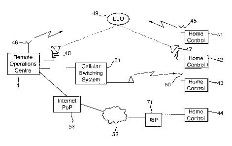
Turning now to Figure 15, as previously mentioned, a home control unit 2 (of
Figure 1 ) communicates with a remote operations centre 4 by way of a
telephone
line. The remote operations centre 4 utilising CLI to determine the location
of the
requesting home control unit and to base transfer of information thereon. In
the
present invention a number of home control units operate in a similar manner
to that
previously described carrying the functions of list creation and maintenance
and code
control for release of apparatus connected within the home. In a further
development
the home control unit 41 may communicate directly with the remote operations
centre 4 by way of radio frequency signals or microwave signals. Thus as
indicated
at 45 the home control unit may be connected to a transmitting aerial while
the home
control unit 4 has a receiving aerial 46. In this case the home control unit
may have
its identity burnt into a storage medium. This is not however a preferred
solution
since if the home control unit 41 was stolen with the equipment in the house,
it
would be possible for an unauthorised user to operate stolen apparatus.
Nevertheless, once the remote operations centre 4 is aware of the theft of a
home
control unit box, including a burnt in identity, it would thereafter decline
to provide
information to the calling home control. As an alternative to the
communication
method of home control unit 41, a home control unit 42 may communicate with
the
remote operations centre by way of a low earth orbital satellite system such
as
indicated by transmission dish 47 and receiver 48 at the remote operations
centre 4.
In this case signals from the home control unit to the remote operations
centre are
reflected by a low earth orbital satellite 49. Again the identity of the home
control
unit 42 may be burnt into the system or may be, as hereinafter described,
determined
by other means.
In yet a further communications method the home control unit 43 is
connected by way of a GSM system 50 to a cellular switching system 51, which
communicates with the remote operations centre 4. In this case the GSM
identity of
the home control unit transmission system is known to the cellular switching
system
and therefore a CLI can be provided the remote operations centre. Further
alternative
coding of the home control unit identity may be provided in addition to the
cellular
SUBSTITUTE SHEET (RULE 26)
CA 02367094 2001-09-13
WO 00/57375 PCT/GB00/00920
switching system identity or the alternative location methods hereinafter
described
may be used.
One potential advantage of using modifiable home control identities might be
the use of an insertable subscriber identity module (SIM) card which may allow
the
5 user to transfer to an alternative home and/or to take the SIM card out of
the home
control unit 43 when not in use, for example when premises are to vacated for
a
period of time.
Finally, home control unit 44 is shown as being connected, for example, by
way of an Internet service provider link 71 and the Internet or world-wide web
52 to
10 the remote operations centre by way of an Internet point of presence 53.
Again
such a connectionless kind of communication either in real time or by way of
electronic mail communication will allow transfer of data between the remote
operations centre and the home control unit 44. Thus for each of the functions
required to be carried out by a home control unit an e-mail message, for
example
15 could be generated comprising the coded information from a stealth aware
appliance
to be transmitted by way of connectionless messaging to the remote operations
centre where a return e-mail can be generated and sent back to the home
control unit
44.
In a still further development of this mode of operation, e-mail messaging
20 capability could be built into stealth aware appliance 5 for example, so
that in the
absence of a home control unit 44 direct communication between a stealth aware
appliance and the remote operations centre could be established, the remote
operations centre being responsive to a serial identity in electronic form
from the
appliance to return appropriate unlock and blanking codes as required.
25 In each of the scenarios of Figure 15 the difficulty of identifying with
certainty the presence of a home control unit with a built in serial number
and tying it
to a particular location has been noted. Thus in Figure 16, to which reference
is now
made, alternative positional location systems may be used. For example, it is
known
that global positioning systems (GPSI using a number of satellites with a
fairly simple
module can locate a unit to an accuracy of less than 30 metres on a global
basis.
With more sophisticated systems location to a little as three metres is
possible. Thus
providing a home control unit or a directly communicating self-aware apparatus
with a
GPS unit, as shown in the home control unit 54, as GPS 55 permits the near
exact
SUBSTITUTE SHEET (RULE 26)
CA 02367094 2001-09-13
WO 00/57375 PCT/GB00/00920
26
location of the requesting home control unit to be identified by use of
triangulation
from two or three GPS satellites representatively shown at 56. thus, prior to
communicating with a remote operations centre the home control processor will
utilise the GPS 55 to determine its co-ordinates and these co-ordinates are
transmitted in the message to the remote operations centre 4. This enables a
secure
home control unit 54 to be used where CLI, for example, is not a practicality
or where
e-mail messaging, Internet communication, or non-locational radio
communication
with the remote operations centre 4 is in use. In this case, the remote
operations
centre 4 need not even be in the same country or connected to the same network
as
the home control unit since the data store at the remote operations centre in
respect
of the particular home control unit will be based on its GPS identity.
In the case of the home control unit 43 (of Figure 15) location of the home
control unit is possible by use of a triangulation system of the cellular
switching
system 51 . As described in published patent application number 824840
comparison
of time delay in signalling between the transmitting aerial 50 of the home
control unit
43 and a number of cellular operator receiving sites, schematically
represented at 57,
allows calculation of the location of the home control unit. Thus in addition
to the
security of the SIM in the home control unit 43, further locational detail can
be
obtained and passed to the remote operations centre 4.
Finally, for completeness and as previously mentioned, the home control unit
58 shows a unit identity module 59 which may be used in place of or in
addition to
each of the locational identity methods of CLI, radio signal triangulation and
GPS
transmissions.
In a further alternative communication between a home control unit and a
remote operations centre 4, direct communication by way of the mains power
line,
for example by means of a locational chip built into an electricity meter
connected to
the mains electricity distribution network could be used. Thus a service
provider,
potentially for example electricity distribution companies, could provide a
control
centre with which communication over the electricity supply using known
protocols
could be used to transfer data to and from a remote operations centre. This
may be
advantageous, for example in apartment blocks where an electricity substation
within
the block could provide service to all of the apartments connected thereto.
The full
functionality of the remote operations centre would thus be provided
monitoring
SUBSTITUTE SHEET (RULE 26)
CA 02367094 2001-09-13
WO 00/57375 PCT/GB00/00920
27
signals on a loop distribution for unit identity and code requests. Again,
where a
communal operations centre in an apartment block is in use it may be possible
to
have direct communication between an apparatus 5 and the operation centre
directly
by way of the electricity supply line.
Having considered alternatives for communication between a remote
operations centre and a home control unit alternative communication techniques
between apparatus 5 and the home control unit 4 now fall to be considered.
In a first alternative development, referring to Figures 17 and 18, in place
of
the FSK interface ( 14 of Figure 2) digital electronic cordless telephone
protocols
(DECT) as used for communication between telephone handsets and base stations
in
domestic premises may be provided. Thus, a DECT interface 60 transmits the
requests as previously described, such requests arising from the reconnection
of the
switch mode power supply 12 and this communication is received on a
corresponding
DECT unit 63 incorporated in the home control unit 2. The signalling is
received by
way of schematically represented aerial 62 which will also transmit the return
information to the apparatus 5 by way of its DECT interface 60. It will be
appreciated that other low power communications techniques could be used, for
example low power radio frequency in other forms than coded in accordance with
DECT protocols could be used.
Figures 19 and 20 show a modification of apparatus 5 and home control unit
2 in which the FSK interface in the apparatus 5 is replaced by a TCP/IP
interface
which may generate electronic messages for transmission either by way of an
intranet connection 66 to a corresponding TCP/IP interface 65 of the home
control
unit or may communicate directly with a remote operations centre by way of the
Internet 67. It will be appreciated that where TCP/IP interface communication
using
an intranet between security aware apparatus 5 and a home control unit 2 is in
use,
then all of the other options for communication between the home control unit
2 of
Figure 20 and the remote operations centre 4 are still available.
It will also be noted that the use of GPS directly in security aware apparatus
5 would enable e-mail messaging directly to the Internet in a secure manner
since
even if the Internet address of either home control unit or the security aware
apparatus is changed, the transmitted data will reflect the true location of
the
requesting apparatus.
SUBSTITUTE SHEET (RULE 26)
CA 02367094 2001-09-13
WO 00/57375 PCT/GB00/00920
28
Having considered various hardware aspects of the apparatus, consideration
is now given to the signalling interchange between an appliance, a home
control unit
and a remote operations centre where such is provided. Referring then to
Figure 5
and also to Figures 11 and 14 hereinbefore described, in Figure 5A is shown
signalling from the home control unit to the remote operations centre request
equipment list 802 received by the remote operations centre as indicated at
step 81 1.
In return at step 815 the remote operations centre returns signalling which is
either
an empty equipment list 803 or, as indicated in Figure 5B, a list containing
apparatus
identities and codings. As indicated in Figure 5B, an unlock code is broadcast
(805 of
Figure 1 1 ) received by security aware apparatus at 308.
Moving now to Figure 5C and referring additionally to Figure 8, on first
connection of the apparatus or on connection of uncoded security aware
apparatus,
when the broadcast timer has expired an unlock request is sent at step 305. In
Figure 5C if the requesting equipment is not in the list then an equipment
code
required message is sent 906 to the remote operations centre, which is
received at
step 820 (Figure 14B) resulting in an equipment code response being
transmitted to
the home control unit at step 826. When received in the home control unit 907
this
results in a system lock enable being transmitted 909 back to the requesting
apparatus, received at 403 of Figure 8A and ultimately results in a response
of
system lock enabled to the home control unit at 411 received (Figure 12 at
974) in
the home control unit which transmits an equipment store confirm message to
the
remote operations centre at 975. The remote operations centre uses the
equipment
stored confirm message received at 828 as a confirmation that the equipment
has
been coded.
Turning to Figure 5D, if the equipment, which sends an unlock request at
305 is in the list as indicated at 902 then, assuming the blanking field is
not enabled,
an unlock response is sent at 905 which is received at 402 of Figure 8.
Figure 5E shows a sequence of events leading to blanking of an appliance. In
this case the customer will have communicated as indicated with the remote
operations centre to request blanking of appliance. Subsequent to this the
customer
will cause the home control unit to reset either by disconnecting power or by
use of a
reset button which will cause the home control unit to contact the remote
operations
centre with a request equipment list message 1802-81 1 ) which will result in
an
SUBSTITUTE SHEET (RULE 26)
CA 02367094 2001-09-13
WO 00/57375 PCT/GB00/00920
29
equipment list being returned 1815-803) to the home control unit with the
blanking
field of the appropriate appliance set. Immediately on receipt of the
equipment list,
because the list is not empty and the home control unit assumes disconnection
of
house power supply, it will broadcast the general unlock code at 805.
Subsequently,
when the customer unplugs the particular appliance or at least disconnects
mains
power and then causes its reconnection, as previously described at step 305,
an
unlock request will be transmitted by the appliance controller to the home
control unit
received at 901. This will result in a blank instruction being returned at
step 912
from the home control unit which, as shown Figure 8A at step 404, will result
in a
system lock disabled response at 415 indicating that blanking has been
completed.
As shown in Figure 13, once a blank response is received at 922, an home
control
unit blank complete message is transmitted to the remote operations centre at
924
resulting in an home control unit blank response being transmitted back to the
home
control unit from the remote operations centre at 840.
Figure 21 shows the component parts of a security system using security
aware appliances 5 of exactly the same form as hereinbefore described, but
arranged
to operate without use of a remote operations centre. Thus, as shown in figure
21 to
which reference is now made, the security aware appliance 5 is connected to
the
mains electricity supply 6 within or connected to which is a security unit,72
either in
the form of a plug in module or built in in some way to the electricity supply
system
as, for example, a dummy power socket or built into the premises electricity
metering
appliance. Also shown are two special units, a blanking key unit 74 and a
memory
unit 75 the function of which is noted hereinafter.
As an alternative to the use of a memory unit 75 as hereinafter referenced, a
back-up security unit 73 may be provided which shadows the output of the
security
unit 72 since there is no other central store of unlocking and blanking coding
for
appliances 5 connected to this kind of system. Thus, if a failure of a
security unit
occurred it could render all appliances in security aware premises 3 to be
rendered
unserviceable.
The security units 72, 73 comprise the same components effectively as
shown in Figure 3, but may additionally include the unit id 59 of Figure 16 or
a GPS
unit 55 which could be used by the stand alone control unit in generating
codes and
SUBSTITUTE SHEET (RULE 26)
CA 02367094 2001-09-13
WO 00/57375 PCT/GB00/00920
which, unless previously blanked, could result in the security unit not
functioning if it
is moved from its known GPS location.
As with the home control unit 2 of Figure 1, when the unit is first connected
to power, as indicated in Figure 22 at 610, it will broadcast an unlock code
at 611
5 before entering its main state at 700. The broadcast unlock code 611 is
always
broadcast if ever power is disconnected from the security unit 72 and then
reconnected. The function of the unlock code is as hereinbefore described to
permit
equipment connected to the system to receive power on reconnection after a
mains
failure. This avoids multiple unlock requests being transmitted simultaneously
from
10 reconnected apparatuses.
Once the unlock code has been broadcast then the processor of the security
unit 72 enters its main state 700 (Figure 23) awaiting an unlock request from
secure
apparatus. Thus turning to Figure 23, on receipt of an unlock request at 701,
the
system checks at 702 to determine whether the item transmitting the request
has an
15 entry in the data store shown in Figure 27. If there is no entry for the
requesting
equipment, as indicated at 702, then at 706 unlock and blanking codes are
created
using, for example, a random number generation program and these unlock codes
and
blanking codes are stored at 708 in the equipment list of Figure 27 and the
number of
appliances in the list is updated. At 709 a system lock enable message is
transmitted
20 to the security aware appliance and a system lock enable timer is set at
710. The
system then awaits a system lock confirm as indicated at 770 of Figure 24 and,
assuming system lock enabled message is received from the security aware
appliance
5 at step 774 returns to the main state of Figure 23.
Should the system lock enable timer expire, as indicated at 771, then the
25 system lock enable message is again transmitted at 772 and the system lock
enable
timer reloaded at 773, the control unit looping back to await system lock
confirm.
In the absence of a system lock confirm being received within a
predetermined (heartbeat) time period may result in the apparatus being
deleted from
the equipment list or marked as unresponsive in the equipment list so that the
30 processor of the home control unit 2 can return to its main state to
monitor for other
equipments.
Returning now to Figure 23 and in particular step 702 where the requesting
equipment appears to be in the list a check is carried out to determine
whether the
SUBSTITUTE SHEET (RULE 26)
CA 02367094 2001-09-13
WO 00/57375 PCT/GB00/00920
31
memory key 75 has been inserted and has transmitted an unlock request with a
memory key identity. If the memory key has been inserted then the list (data
store
Figure 27) of the security unit 72 is dumped using the same transmission
method as
is used to the security aware appliances. The memory key may either be stored
in a
safe place by the occupier of the premises 3 or may be used to dump the list
to an
operations centre either by direct transfer or by telephonic transfer.
Assuming that the memory key 75 has not been inserted, a check is now
carried out to determine whether the unlock request has occurred while the
blanking
key 74 is also connected to the system. If the blanking key is not present
then the
unlock code for the particular appliance is located at 704 and an unlock
response is
transmitted at 705 prior to the unit returning to the main state 700.
If an appliance is disconnected and reconnected and the blanking key is
inserted either directly to the security unit or by way of the mains
electricity supply,
then an equipment code covering timer is loaded at 711 and a blanking
instruction
including the blanking code is transmitted at 712. A timer is started at 713
and the
system now waits for the blank response to come from the security aware
appliance
5 at step 720. Referring then to Figure 25 briefly, if the blank covering
timer expires
without response from the security aware appliance 5 then the processor of the
security unit 72 will return to its main state without taking further action.
If however
the blank response is received, as indicated at step 722, then the particular
appliance
is removed from the list and the number of appliances in the list updated
accordingly.
The backup unit 73 may function in the same way as the memory key 75 in
that the security unit may periodically do a list dump to the backup unit so
that the
data storage in each of the units is comparable. The blanking key 74 may
include
coding so that only a blanking key relating to the particular security unit 72
can ever
be used with the particular security unit to blank security aware appliances
5.
Thus considering the signalling interchanges between the home control and
appliances reference is made to Figure 26, the first being Figure 26A where on
connection of mains power (Figure 22 610) a broadcast unlock code is
transmitted
for receipt by the appliance controller so that if a complete domestic mains
failure has
occurred then this will be received as indicated in Figure 8, 308, in exactly
the same
manner as for other home control units using the remote operations centre.
SUBSTITUTE SHEET (RULE 26)
CA 02367094 2001-09-13
WO 00/57375 PCT/GB00/00920
32
Turning again to Figure 23 and also to Figure 8, when an unlock request is
transmitted by a security aware appliance 5 as indicated at 305, then as shown
in
Figure 26B if the apparatus is not currently in the equipment list then a
system lock
enable message will be created at 709 for reception as indicated at 403 of
Figure 8A.
This will result in a system lock enable message being returned at 411 to
enable the home control unit 72 to add the apparatus tot he list.
If as indicated at 702 the equipment is present in the data store, then an
unlock response 705 is returned as shown in Figure 26C.
Now as shown in Figure 26D, in the case where at 703 a blanking key is
present, then on receipt of the unlock request a blank instruction will be
sent to the
particular appliances once it is plugged back in or has mains reconnected
thereto. As
indicated in Figure 8A the unlock and blanking codes fields are reset and a
system
lock disabled (blank response) is transmitted at 415.
It is here noted that the security unit 72 may communicate with security
aware appliances in any of the appropriate manners previously determined
including
but not limited to FSK signalling across a mains electricity supply, low
powered radio
signalling or DECT signalling. Intranet communication may also be used.
SUBSTITUTE SHEET (RULE 26)