Note : Les descriptions sont présentées dans la langue officielle dans laquelle elles ont été soumises.
CA 02368158 2001-09-18
WO 00/56390 PCT/US00/03725
-1-
FREE STANDING FILTER
Technical Field
The present invention relates generally to small filters for insertion into a
vein
or artery, and more particularly to a filter which, when expanded, is free
standing in
engagement with a body vessel without penetrating the vessel wall.
Background of the Invention
In recent years, a number of medical devices have been designed which are
adapted for compression into a small size to facilitate introduction into a
body vessel
such as an arterial or vascular passageway and which are subsequently
expandable into
contact with walls of the passageway. These devices, among others, include
stents, such
as those shown by U.S. Patent No 5,540,712 and blood clot filters such as
those shown
by U.S. Patent No. 5,669,933 which expand and are held in position by
engagement
with the inner wall of a vessel. It has been found to be advantageous to form
such
devices of a thermal shape memory material having a first, relatively pliable
low
temperature condition and a second, relatively rigid high-temperature
condition. By
forming such devices of temperature responsive material, the device in a
flexible and
reduced stress state may be compressed to fit within the bore of a delivery
catheter when
exposed to a temperature below a predetermined transition temperature, but at
temperatures at or above the transition temperature, the device expands and
becomes
relatively rigid.
CA 02368158 2001-09-18
WO 00/56390 PCT/USOO/03725
-2-
Known self expanding medical devices have been formed of Nitinol, an alloy
of titanium and nickel which provides the device with a thermal memory. The
unique
characteristic of this alloy is its thermally triggered shape memory, which
allows a
device constructed of the alloy to be cooled below a temperature
transformation level
to a martensitic state and thereby softened for loading into a catheter in a
relatively
compressed and elongated state, and to regain the memorized shape in an
austenitic state
when warmed to a selected temperature, above the temperature transformation
level,
such as human body temperature. The two interchangeable shapes are possible
because
of the two distinct microcrystalline structures that are interchangeable with
a small
variation in temperature. The temperature at which the device assumes its
first
configuration may be varied within wide limits by changing the composition of
the
alloy. Thus, while for human use the alloy may be focused on a transition
temperature
range close to 98.6 F, the alloy readily may be modified for use in animals
with
different body temperatures.
In recent years advances have been made in the treatment of blood vessel
stenosis or occlusion by plaque, thrombi, embolic, or other deposits which
adversely
reduce or block the flow of blood through a vessel. Balloon angioplasty or
similar
transluminal treatments have become common for some blood vessel lesions, but
for all
such procedures, plaque and emboli dislodged during the procedure are free to
flow
within the lumen of the vessel and possibly cause substantial injury to a
patient.
In an attempt to contain and remove emboli and other debris, balloon
angioplasty coupled with irrigation and aspiration has been performed as
illustrated by
U.S. Patent No. 5,883,644 and International Publication No. WO 98/39046 to
Zadno-
Azizi et al. This procedure requires complete vessel occlusion cutting off all
blood flow
which imposes severe time constraints on the procedure. Additionally, the
balloons
involved in the procedure are affixed to elongate guidewires or small elongate
catheters
which extend for a substantial distance through blood vessels to the location
of the
stenosis or occlusion, and it is practically impossible to prevent some back
and forth
CA 02368158 2001-09-18
WO 00/56390 PCT/US00/03725
-3-
longitudinal motion of these elongate elements within a vessel during a
procedure. This
movement of the guidewire or catheter to which a balloon is attached causes
the balloon
to move back and forth and abrade emboli from the vessel wall downstream of
the
balloon containment area.
Angioplasty is often not a preferred treatment for lesions in the carotid
artery
because dislodged plaque can enter arterial vessels of the brain causing brain
damage
or even death. As indicated by U.S. Patent No. 5,879,367 to Kaganov et al.,
carotid
endarterectomy is a surgical procedure used to remove a lesion in the carotid
artery, but
this procedure also involves substantial risk of dislodged embolic material.
In an attempt to contain dislodged emboli during a procedure to clear blood
vessel stenosis or occlusion, a variety of distal filters have been devised
such as those
shown by U.S. Patent No. 5,814,064 and International Publication Nos. WO
98/38920
and WO 98/39053 to Daniel et al: as well as U.S. Patent Nos. 5,827,324 to
Cassell et
al., 5,846,260 to Maahs and 5,876,367 to Kaganov et al. These filters are
secured to the
distal portion of a guidewire or catheter and are deployed distally from the
stenosis or
occlusion to capture embolic material. Once the distal filter is positioned
and expanded
into contact with the wall of the blood vessel, an angioplasty balloon, a
stent, or other
devices are introduced over the proximal end of the guidewire or catheter to
which the
filter is attached and moved into position in the area of the occlusion or
stenosis spaced
proximally from the filter.
Known guidewire or catheter attached distal filters have been subject to a
number of disadvantages. First, since the elongate catheter or guidewire to
which the
filter is attached is used to guide over the wire devices during a subsequent
procedure,
it is extremely difficult if not impossible to prevent longitudinal movement
of the wire
or catheter after the filter has been deployed. This causes the filter to move
back and
forth within the vessel with resultant abrasion by the filter of the vessel
wall, and such
abrasion not only causes trauma to the vessel wall but also operates to
dislodge debris
which is free to flow distally of the filter. Thus filter movement after the
filter is
CA 02368158 2001-09-18
WO 00/56390 PCTIUSOO/03725
-4-
deployed somewhat defeats the purpose of the filter. Also, it is often
desirable during
a procedure to exchange guidewires, and such an exchange is not possible with
an
attached filter.
Finally the retrieval of known distal filters while retaining captured embolic
material has proven to be problematic. Many cone shaped filters with wide,
upstream
proximal open ends tend to eject captured embolic material through the open
end as the
filter is collapsed. Also, many distal filters are formed by a mesh material
which is
expanded by a filter frame, and when the frame closes to collapse the filter
for
withdrawal through a catheter, the mesh folds creating outwardly projecting
pleats.
These pleats snag on the withdrawal catheter making retrieval of the filter
difficult and
often causing the filter to spill captured embolic material.
Summary of the Invention
It is a primary object of the present invention to provide a novel and
improved
free standing filter for expansion within a blood vessel to capture dislodged
embolic
material.
Another object of the present invention is to provide a novel and improved
free
standing filter for use during a procedure to treat blood vessel stenosis or
occlusion
which does not cause trauma to the luminal wall during guidewire balloon and
stent
exchanges.
A further object of the present invention is to provide a novel and improved
free
standing filter for use during a procedure to treat blood vessel stenosis or
occlusion
which is formed to facilitate intra-procedural guidewire exchanges.
Yet another object of the present invention is to provide a novel and improved
free standing filter for use during a procedure to treat blood vessel stenosis
or occlusion
which is formed to remain stationary after expansion independent of guidewire
or
catheter motion.
CA 02368158 2006-07-27
-5-
A further object of the present invention is to provide a novel and improved
free
standing filter for use during a procedure to treat blood vessel stenosis or
occlusion which
includes an elastomeric or knitted fiber mesh which collapses without pleating
during the
filter recovery process.
A still further object of the present invention is to provide a novel and
improved free
standing filter for use during a procedure to treat blood vessel stenosis or
occlusion which is
formed to capture and safely remove embolic material. The filter is provided
with a proxi-
mal end designed for docking with a recovery system and which operates to
positively close
the open end of a filter mesh as the filter is collapsed during recovery.
These and other objects of the present invention are accomplished by providing
a free
standing filter with a filter body having an elongate guidewire receiving
member extending
centrally therethrough to define an open ended channel configured to receive a
plurality of
different sized guidewires. An expandable and contractible frame surrounds the
elongate
guidewire receiving member and is connected at a proximal end to the elongate
guidewire
receiving member. A porous embolic capturing unit has an open end connected to
the frame
and a closed end connected to the elongate guidewire receiving member which
extends
through through the porous embolic capturing unit.
The invention also provides according to an aspect, for a free standing filter
for
introduction along an elongate guidewire into a blood vessel and expansion
radially into
contact with the vessel wall to capture emboli in the blood flowing through
the vessel. The
filter comprises a filter body having a first end and a second end spaced from
the first end,
the filter body including an elongate guidewire receiving member extending
between the
first and second ends of the filter body, the elongate guidewire receiving
member defining an
open ended channel sized to receive and permit passage of a guidewire through
the elongate
guidewire receiving member and to permit relative movement therebetween. The
filter also
comprises an expandable and contractible frame connected to and surrounding
the elongate
guidewire receiving member, the frame being adapted to move between a first
contracted
position adjacent to the elongate guidewire receiving member to a second
expanded position
spaced radially from the elongate guidewire receiving member. A porous emboli
capturing
unit is connected to the frame.
CA 02368158 2006-07-27
- 5a-
Brief Description of the Drawings
Figure 1 is a view in side elevation of the free standing filter of the
present invention
in the expanded configuration;
Figure 2 is a partially sectional view in side elevation of a second
embodiment of the
free standing filter of the present invention;
Figure 3 is a partially sectional view of the free standing filter of Figure 2
within a
delivery tube;
CA 02368158 2001-09-18
WO 00/56390 PCT/USOO/03725
-6-
Figure 4 is a sectional view of a positioning and recovery unit for the free
standing filter of Figure 2; and
Figure 5 is a sectional view of the positioning and recovery unit of Figure 4
engaged with the free standing filter.
Description of the Preferred Embodiments
Referring to Figure 1, the free standing filter 10 of the present invention is
formed around a central tube 11 which forms the longitudinal axis for the
filter 10 and
slidingly receives a guidewire 12. The frame of the filter is formed by a
stent 14 which
may be collapsed inwardly toward the tube 11 and which expands outwardly away
from
the tube to the substantially cylindrical open ended configuration shown in
the
drawings. Ideally, this stent is formed of thermal shape memory material and
is of the
type shown by U.S. Patent No. 5,540,712, although other expandable stents can
be used.
The stent 14 is coupled at one end to the central tube 11 by elongate lead
wires 16 which
extend between an open proximal end 18 of the stent and a spaced coupling 20
which
is secured to the central tube 11.
Extending around the stent 14 and attached thereto is a flexible, fine mesh
filter
material 22 which opens at the proximal end 18 of the stent and covers the
body of the
stent. Ideally, the stent extends over this mesh filter material. At the
distal end 24 of
the stent, the fine mesh filter material projects outwardly to form a flexible
conical
section 26 with an apex 28 connected to a coupling 30 which slides on the tube
11 in
spaced relation to the stent distal end 24. Thus when the stent expands as
shown in the
drawings, the mesh filter material forms a substantially cylindrical section
32 which
opens at the proximal end of the stent and a flexible, closed conical section
26 which
extends beyond the distal end of the stent to catch and collect small
particles. The fine
CA 02368158 2001-09-18
WO 00/56390 PCT/US00/03725
-7-
filter mesh may be formed of suitable biocompatible material such as polyester
or a
PTFE material and is coated with thromboresistant materials such as, for
example,
Phosphoral Choline or Hyaluronic Acid. The mesh is a braided material or
elastomeric
mesh which normally conforms to the exterior shape of the central tube 11, but
which
stretches to expand outwardly away from the tube when the stent 24 expands.
Thus the
mesh is biased toward the tube 11, and when the stent collapses inwardly
toward the
tube, the mesh contracts back to the exterior shape of the tube and does not
form pleats.
In the operation of the filter 10, the stent with the mesh filter material is
inserted
in a collapsed condition into a delivery tube 34 and guidewire 12 extends
through the
central tube 11. Then the delivery tube is used to deliver the filter 10 over
the guidewire
12 to a desired position within a body vessel whereupon the filter is ejected
from the
delivery tube. Now the previously collapsed stent 14 expands into contact with
the
walls 36 of the vessel (shown in broken lines) thereby expanding the flexible
mesh filter
material which was previously collapsed within the delivery tube with the
stent. The
guidewire 12 may now be used to guide other devices into the vessel, and since
the
guidewire can move freely in a longitudinal direction within the tube 11,
longitudinal
movement of the guidewire will not result in movement of the expanded filter.
Once the stent 14 has expanded against the wall 36 of the vessel, the
guidewire
12 can be removed and replaced with a new guidewire of a different size. The
tube 11
is preferably formed of sufficient size to accept.014 inch diameter to.035
inch diameter
guidewires. It may often be desirable to initially use a very fine guidewire
(.014") to
cross a lesion and position the filter 10 and to then exchange this fine
guidewire for a
thicker wire.
The fine mesh filter materia122, when expanded, should have a pore size within
a range of 50 m to 300 m to capture and retain embolic material sized in
excess of
the pore size while permitting blood flow in the direction of the arrow 38
line in Figure
1 between the wires 16 and into the proximal end 18 of the stent 14. The blood
and
embolic material flows through the and into the flexible conical section 26 of
the fine
CA 02368158 2001-09-18
WO 00/56390 PCT/USOO/03725
-8-
mesh filter material where the embolic material is trapped while the blood
passes
through the filter material.
To remove the filter 10 with the captured embolic material, the stent 14 is
collapsed against the tube 11 for withdrawal through a catheter or delivery
tube 34.
Preferably the stent is formed of the thermal shape memory material such as
nitinol or
other materials, for example, including but not limited to Titanium, stainless
steel,
MP35N alloys or other similar materials and may be collapsed by cooling the
stent to
a temperature below a transition temperature. It is important to note that the
embolic
material has been captured within the conical section 28, so that when the
stent collapses
against the tube 11, it positively closes the mouth of the conical section
preventing
material from escaping as the filter is drawn into the tube 34. The stent
forces the entire
longitudinal extent of the section 32 against the tube I 1 to prevent the
escape of material
from the conical section 28.
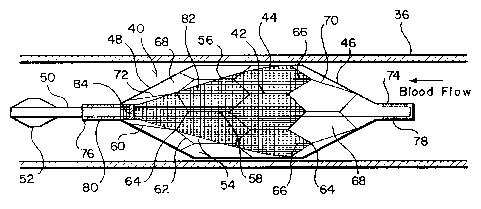
Referring now to Figures 2 and 3, a second embodiment of the free standing
filter of the present invention is indicated generally at 40. For unimpeded
passage
through a catheter or delivery tube 34, it is beneficial to form a filter with
a frame which
completely surrounds and protects the filter mesh material. Thus the filter 40
includes
a cellular frame 42 which is preferably formed of thermal shape memory
material such
as nitinol, and this frame when expanded includes a central section 44 having
a
substantially tubular configuration, a proximal end section 46 and a distal
end section
48, both having a substantially conical configuration. A central tube 50,
similar in size
to the tube 11, forms the central longitudinal axis for the filter 40 and
extends through
the filter and outwardly from the proximal and distal sections of the frame
42. The
distal end of the tube 50 is provided with a tapered atraumatic molded tip 52
configured
to center and guide the filter within the delivery tube 34.
The central section 44 of the frame 42 includes a plurality of interconnected
cells
54 which are substantially equal in size and which are defined by spaced
sidewalls 56
and 58 which extend substantially parallel to the tube 50 and the longitudinal
axis of the
WO 00/56390 CA 02368158 2001-09-18 PCT/US00/03725
-9-
filter. Adjacent cells 54 in a row of cells extending around the central tube
50 are
connected together by their adjacent sidewalls 56 and 58, and these sidewalls
remain
substantially parallel to the tube 50 in both the expanded and collapsed
configuration
of the filter 40 as illustrated in Figures 2 and 3. The opposite ends of each
cell are
formed by outwardly inclined endwall sections 60 and 62 which meet at an apex
64.
Extending in a distal direction from the apex 64 of alternate cells 54 at the
proximal end
of the central section 44 are short, straight stabilizers 66 which engage the
vessel wall
36 when the filter is expanded and aid to preclude movement of the filter in a
distal
direction.
The proximal end section 46 and distal end section 48 of the frame 42 are
formed of cells 68 with tapered sidewalls 70 and 72 which extend at an angle
to the
central tube 50 to form the tapered conical end sections of the frame.
Proximal end
section 46 of the frame is secured to the tube 50 by a coupling 74, and distal
end section
48 is secured to a coupling 76 which slides on the tube 50. The couplings 74
and 76 are
provided with radiopaque markers 78 and 80 respectively.
Fine mesh filter material 82 of the type previously described for the filter
10 is
positioned within the central and distal sections of the frame 42. This filter
material is
bonded to at least the first row of cells 54 in the proximal end of the
central section 44
of the frame, and at the distal end of the frame the filter material is
secured to the tube
50 adjacent to the coupling 76 by a coupling 84. Thus the filter material
forms a cone
when the filter 40 is expanded, and the open proximal end of the cone is
positively
closed when the proximal end row of cells of the central section 44 collapse
against the
tube 50.
As shown in Figure 3, when the filter 40 moves along the guidewire 12 through
the delivery tube 34, the mesh filter material 82 is enclosed within the frame
42 which
protects the filter material. Also, when an expanded filter is contracted and
drawn back
into the delivery tube, the frame engages the delivery tube and precludes the
filter from
catching or snagging on the delivery tube.
CA 02368158 2006-07-27
-10-
Figures 4 and 5 disclose a positioning and recovery system 94 for the filter
40.
This system includes an elongate, flexible, tubular member 86 having a docking
end 88
for receiving the coupling 74 of the filter 40. The docking end is provided
with a
plurality of longitudinally extending lumens 90, two of which are shown in
Figures 4
and 5, and an outwardly inclined hook 92 of flexible material, such as
stainless steel, is
mounted in each lumen to extend outwardly from the docking end of the tubular
member 86.
When the filter 40 is collapsed within the delivery tube 34 as shown in Figure
3, the tubular member 86 with the hooks 92 engaged with the cells 68 extends
over the
guidewire 12 to move the filter through the delivery tube. When the filter is
ejected
from the delivery tube and the hooks 92 extend outwardly from the end of the
delivery
tube, the hooks spring open as illustrated in Figure 4 releasing the filter.
If desirable,
the filter can be moved further from the delivery tube by the engagement
between the
filter and the stepped docking end ofthe tubularmember 86 before the
deliverytube and
the docking and positioning system are withdrawn.
To recover the filter, the tubular member 86 with the hooks 92 compressed as
shown in Figure 5 is passed through the delivery tube and outwardly therefrom
until the
hooks spring open and are positioned over the cells 68 as shown in Figure 4.
Now the
delivery tube is moved over the hooks to compress and engage the hooks with
the cells
68 as shown in Figure 5, and once the hooks are engaged, the filter can be
drawn back
into the delivery tube by the tubular member 86.