Note : Les descriptions sont présentées dans la langue officielle dans laquelle elles ont été soumises.
CA 02368507 2002-O1-18
79443-1
Field of the Invention
The present invention is related to the field of
boat trailers and equipment for loading and unloading boats
from boat trailers. More particularly, the present
invention is related to the field of boat trailers and
equipment for guiding boats during loading and unloading
from boat trailers.
Background of the Invention
l0 A boat trailer is usually used to transport a boat
over land. A standard boat trailer consists of a frame, two
or more wheels attached to the frame, and a winch stand near
the front of the trailer which supports a winch and cable
system. A number of rubber rollers on the frame facilitate
loading and unloading the boat from the trailer and secure
the boat on the trailer during transport.
A boat ramp is ordinarily used for loading a boat
from the water onto the trailer or unloading a boat from the
trailer.into the water. In fact, most boating facilities
are equipped with at least one boat ramp. A boat ramp has a
surface (usually paved) that gradually slopes toward the
water and for some distance below the surface of the water.
A boat dock is usually installed on at least one side of and
parallel to the boat ramp.
To load a boat from the water onto the trailer,
the driver of the vehicle backs the trailer down the boat
ramp into the water until the trailer reaches an appropriate
depth. The boat is usually tied to the dock at this point.
The appropriate depth for the trailer is often difficult to
3o determine, and may only be learned through trial and error
or experience. In any event, when the trailer is at an
appropriate depth, the front of the trailer and winch stand
1
CA 02368507 2002-O1-18
79443-1
are usually just above the surface of the water while the
rear of the trailer is submerged well below the surface.
The boat is guided from the dock toward the
trailer, and the bow of the boat is connected to the winch
cable. At this point, the bow usually engages the rollers
near the front of the trailer as they are either just below
or just above the surface of the water. However, the stern
does not engage the rollers at the back of the trailer as
these rollers are too deep in the water. As a result, there
1o is nothing on a standard boat trailer to restrict the
movement of the stern of the boat, and it is free to wander
to one side or the other. This wandering makes the boat
difficult to control, and can make loading the boat a
difficult task, especially for a single person, and
especially in adverse conditions, such as windy or rough
weather, or where the boat ramp slopes to one side or the
other.
The boat is then pulled by the winch until the bow
engages a roller on the winch stand. At this point, the
stern of the boat still may not engage the rollers at the
back of the trailer. The stern must be centered on the
trailer as best as possible, after which time the driver
pulls the trailer out of the water. As the trailer is
pulled from the water, the stern of the boat will settle on
the rollers at the back of the trailer. However, if the
stern was not centered correctly, it might not properly
engage those rollers. The trailer would then have to be
backed into the water, and the above procedure repeated.
This could take several attempts, depending on the
experience of the driver and/or the conditions at the boat
ramp.
To unload a boat from a boat trailer into the
water, the driver of the vehicle backs the trailer down the
2
CA 02368507 2002-O1-18
79443-1
boat ramp until the trailer reaches an appropriate depth.
Again, this depth can be difficult to determine. Once the
trailer has been submerged, the stern of the boat will float
above the rollers at the back of the trailer, and may wander
to one side or the other. The winch is released and the
boat is slid along the rollers until the entire boat is
disengaged from the rollers. At this point, the entire boat
may wander. If the boat wanders away from the dock; it can
be difficult to retrieve.
A number of solutions to the problems associated
with loading and unloading boats from trailers have been
proposed. For example, U:S. Patent No. 4,340,332 issued on
July 20, 1982 to Davies describes two quadrilateral shaped
gates which are pivotally attachable to the rear corners of
a boat trailer. With the trailer on a boat ramp out of the
water, the boom gates are manually pivoted from a forward
transporting position alongside the trailer to a rearward
guiding position out over the water and alongside a floating
boat. Once the boat is loaded, the gates are manually
pivoted back to the transporting position. As described
above, the gates must be manually operated in order for the
invention to function.
U.S. Patent No. 5,165,706 issued on November 24,
1992 to Fond describes a boat-shaped guide having a closed
and an open end, the closed end being pivotally attachable
to the front of a boat trailer. The guide is biased by an
elevation means such as a gas charged cylinder or a coil
spring so as to elevate relative the trailer. When the boat
is resting on the guide, the elevation means is overcome and
the guide remains in a lowered position. When the weight of
the boat is removed, the elevation means causes the guide to
elevate. The elevated guide helps keep the boat centered in
the water during loading and unloading from the trailer:
3
CA 02368507 2002-O1-18
79443-1
However, it should be noted that this guide is not easily
adaptable to fit boats of various shapes and sizes. In
addition, a specialized winch stand must replace the
standard winch stand of the trailer in order to accommodate
the elevation means.
In addition, a number of specialized boat trailers
have been described. U.S. Patent No. 5,228,713 issued on
July 20, 1993 to Kovach, U.S. Patent No. 5,013,206 issued on
May 7, 1991 to Ernst et al., U.S. Patent No. 5,332,249
issued on July 26, 1994 to Solberg et al., U.S. Patent No.
4,395,185 issued on July 26, 1983 to Whaley and U.S. Patent
No. 5,004,260 issued on April 2, 1991 to Smyly, Sr. each
describes specialized boat trailers. These trailers often
involve complicated mechanisms, and can be difficult to
operate and expensive to purchase.
Summary of the Invention
In a broad aspect, the present invention provides
a trailer-mounted boat guiding means for keeping a boat
centered in the water in relation to a boat trailer during
loading and unloading of said boat from said trailer, said
boat guiding means comprising a left and right boat guiding
mechanism attachable to a left and a right side of said
trailer respectively, each of said boat guiding mechanisms
comprising a trailer attachment means for attaching said
boat guiding mechanism to a side of said trailer, a
supporting member having a first end and a second end, said
first end being connected to said trailer attachment means,
and said second end being displaced outwardly and upwardly
relative to said first end, a guiding arm pivotally
connected to said second end of said supporting member to
allow said guiding arm to pivot upwardly from a,transport
position to a boat guiding position, and a flotation means
4
CA 02368507 2002-O1-18
79443 -1
associated with said guiding arm, wherein said flotation
means is of sufficient buoyancy, and is so associated with
said guiding arm, so as to cause said guiding arm to pivot
upwardly from the transport position to the boat guiding
position when said trailer is submerged in the water for
loading or unloading said"boat from said trailer.
In one embodiment, the position of the guiding
arms on the guiding mechanisms are adjustable in three
dimensions relative to the boat trailer to ensure that the
present invention can be used with boats of varying shapes
and sizes. Similarly, the means of attaching the present
invention to the boat trailer is also adjustable to ensure
the present invention is attachable to most standard boat
trailers.
In another embodiment, the boat guiding mechanisms
have a stopping means for controlling downward rotation of
the guiding arms relative to the supporting members past the
stopping means. As a result, the downward rotation of the
guiding arms can be controlled.
There is further provided a boat trailer,
comprising a boat frame, a vehicle attachment means
connected to said frame, a plurality of wheels connected to
said frame, and a left and right boat guiding mechanism near
the rear of each of a left and right side of said frame
respectively, for keeping a boat centered in the water
during loading and unloading of said boat from said trailer,
each of said boat guiding mechanisms comprising a supporting
member having a connected end and a second end, said
connected end being attached to said frame, and said second
end being displaced outwardly and upwardly relative to said
connected end, a guiding arm pivotally connected to said
second end of said supporting member to allow said guiding
arm to pivot upwardly from a transport position to a boat
5
CA 02368507 2002-O1-18
79443-1
guiding position, and a flotation means associated with said
guiding arm, wherein said flotation means is of sufficient
buoyancy, and is so associated with said guiding arm; so as
to cause said guiding arm to pivot upwardly from the
transport position to the boat guiding position when said
trailer is submerged in the water for loading or unloading
said boat from said trailer.
The present invention is an important improvement
upon other boat guiding means described above in that it is
l0 simple and inexpensive to construct, easy to operate and
attachable to most standard boat trailers. In addition, if
brightly coloured, the flotation means and/or guiding arms
can act as indicators to the driver that the boat trailer
has reached an acceptable depth in the water for loading or
unloading the boat. When the guiding arms begin to float
approximately parallel to and near the surface of the water,
the trailer has reached an acceptable depth. Finally,
depending on the material selected, the flotation means can
also act as a bumper to prevent damage to the boat from
contact with the guiding arms.
Brief Description of the Drawings
Having generally described the nature of the
invention, preferred embodiments will now be described with
reference to the accompanying drawings, in which:
Figure 1 is a side view of a standard boat trailer
equipped with an embodiment of the guiding mechanisms of the
present invention. The near guiding mechanism (shown) is
obstructing the view of the far guiding mechanism (not
shown) .
Figure 2 is a side view of the trailer in Figure
1, after having been submerged in the water.
6
CA 02368507 2002-O1-18
79443-1
Figure 3 is a side perspective view of the near
guiding mechanism depicted in Figures 1 and 2.
Figure 4 is an end view of the guiding mechanism
of Figure 3 taken along line A-A.
Figure 5 is a side fragmentary view of a lower
portion of another embodiment of the guiding mechanism of
the present invention.
Figure 6 is an end fragmentary view of the guiding
mechanism of Figure 5 taken along line B-B.
Figure 7 is a top fragmentary view of the guiding
mechanism of Figure 5 taken along line C-C.
Figure 8 is a side fragmentary view of an upper
portion of another embodiment of the guiding mechanism of
the present invention.
Figure 9 is a side fragmentary view of an upper
portion of yet another embodiment of the guiding mechanism
of the present invention.
Figure 10 is an end fragmentary view of the
guiding mechanism of Figure 9 taken along line D-D.
Figure 11 is a side fragmentary view of an upper
portion of another embodiment of the guiding mechanism of
the present invention.
Figure 12 is an end fragmentary view of the
guiding mechanism of Figure 11 taken along line E-E.
Description of Preferred Embodiments
The particularly illustrated embodiments are
described in this section with reference to the drawings.
Figure d shows a standard boat trailer 2 which has been
equipped with a preferred embodiment of the guiding
mechanisms 4 of the present invention. The boat trailer
7
CA 02368507 2002-O1-18
79443-1
consists of a boat-shaped frame 6, two or more wheels 8
attached to the frame, and a winch stand 10 near the front
of the trailer which supports a winch and cable system. The
boat shaped frame 6 comprises two side rails 12 along each
side of the trailer which meet at a point near the front of
the trailer, and which are connected to one another by
several cross rails (not shown). A number of rubber rollers
(not shown) on the side rails and cross rails, from the
front of the trailer to the rear, facilitate loading and
unloading the boat from the trailer, and secure the boat on
the trailer during transport. The guiding mechanisms 4 are
attached to the side rails 12 near the rear of each side of
the boat trailer 2. The near guiding mechanism 4 (shown) is
obstructing the view of the far guiding mechanism (not
shown) .
In Figure 2, the boat trailer depicted in Figure 1
has been submerged in the water so that the trailer is in a
pre-loading or post-unloading position.
Figures 3 to 12 depict various embodiments of one
of the two guiding mechanisms of the present invention. It
will be generally understood that in each case the opposite
guiding mechanism (not shown) is a mirror image of that
depicted in Figures 3 to 12.
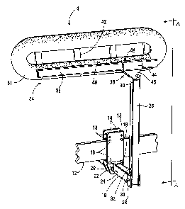
With reference to Figures 3 and 4, the guiding
mechanism 4 of the preferred embodiment consists of a pair
of mounting plates 14 placed on opposite sides of the side
rail 12 of the boat trailer near the rear of the trailer.
One or more bolts 16 through the mounting plates l4 are used
to hold the mounting plates in place on the side rail 12.
The bolts 16 will be of sufficient length to be able to
accommodate side rails 12 of various widths. A series of
holes 18 are drilled in the mounting plates 14 to allow for
attachment of the mounting plates to side rails 12 of
8
CA 02368507 2002-O1-18
79443-1
various heights. In the embodiment shown, the mounting
plates 14 are placed on the left and right side of the side
rail 12. However, as discussed in more detail below; a
modified version of the mounting plates may alternatively be
placed on the top and bottom of the side rail.
A substantially horizontal spacer bar 18 with an
inner end and an outer end is connected to the mounting
plates 14. In the embodiment shown, the lower ends of the
mounting plates 14 have sleeves 20 adapted to receive the
l0 inner end of the spacer bar 18. One or more bolts 22 pass
through the sleeves 20 and spacer bar 18 to hold the bar in
place. A series of elongated holes 24 are drilled in the
spacer bar 18 to allow for inward or outward adjustment of
the spacer bar 18 relative to the mounting plates 14. Thus,
the position of the spacer bar ds easily adjustable relative
to the boat trailer, which helps ensure that the guiding
mechanisms will be able to accommodate boats of various
shapes and sizes. The holes are elongated to ensure that
the mounting plates 14 will be able to accommodate side
rails 12 of various widths when the spacer bar 18 is
attached. In the alternative, one or two highly elongated
slots in the spacer bar l8 could be used.
A substantially vertical support post 26 with a
top end and a bottom end is connected at its bottom end to
the outer end of the spacer bar 18. In the embodiment
shown, a sleeve 28 at the outer end of the spacer bar 18 is
adapted to receive the bottom end of the support post 26. A
bolt 30 passes through the sleeve 28 and support post 26 to
hold the post in place. A series of holes 32 are drilled
along the support post 26 to enable the elevation of the
support post to be adjustable relative to the spacer bar l8.
This allows for the elevation of the support post to be
easily adjustable relative to the boat trailer, and helps
9
CA 02368507 2002-O1-18
79443-1
ensure that the guiding mechanisms will be able to
accommodate boats of various shapes and sizes.
~-~ A guiding arm 34 is connected to the top end of
the support post 26 by means of a hinge bracket 36. In the
embodiment shown, the guiding arm consists of an elongated
bracket-receiving bar 38 attached by means of a connection
flange 39 to a flotation support frame 40. The flotation
support frame 40 comprises an upper and lower horizontal
flotation support (not shown) connected by a series of
vertical flotation supports 42. The hinge bracket 36
comprises a sleeve 44 having an inward and outward side,
adapted to receive the bracket-receiving bar 38 of the
guiding arm 34. A bolt 46 passes through the sleeve 44 and
bracket-receiving bar 38 of the guiding arm 34 to hold the
arm in place. A series of holes 48 in the bracket-receiving
bar 38 of the guiding arm 34 are capable of receiving the
bolt 46. This allows for the position of the guiding arm 34
to be easily adjustable forwardly or rearwardly relative to
the boat trailer. Two substantially parallel downward
projections 45 extend downward from the inward and outward
side of the sleeve 44 of the hinge bracket 36 and are
adapted to receive the top end of the support post 26. The
hinge bracket 36 is pivotally connected to the top end of
the vertical support post 26 by means of a hinge pin 50
inserted through the downward projections 45 and support
post 26. The guiding arm 34 is thus able to pivot upwardly
or downwardly relative to the support post 26 about the
hinge pin 50.
A flotation element 51 is associated with the
guiding arm 34 so as to cause the guiding arm 34 to pivot
upward relative to the support post 26 so that it remains
approximately parallel to and near the surface of the water
when the trailer has been submerged to an appropriate depth
l0
CA 02368507 2002-O1-18
79443-1
for loading or unloading a boat. This association could be
the attachment of the flotation element to the guiding arm,
as in the embodiment depicted, where segments of foam tubing
have been attached to the flotation support frame 40 of the
guiding arm 34. In the place of foam tubing, air filled or
rubber bumpers, Styrofoam segments, and the like, would also
be acceptable. Alternatively (not shown), the association
of the flotation element with the guiding arm could be the
incorporation of the flotation element within the guiding
arm. This could include placing the flotation element, such
as air, another gas, or foam, inside the guiding arm:
Finally, the association of the flotation element with the
guiding arm could be the incorporation of the flotation
element as part of the guiding arm or as the guiding arm
itself (not shown). This would include an embodiment where
the guiding arm was constructed partly or entirely of a
buoyant material.
In Figures 5, 6 and 7, an alternative embodiment
is shown. In Figures 5, 6 and 7, the spacer bar l8 is
connected to the side rail 12 of the boat trailer by upper
and lower horizontal mounting plates 52. The mounting
plates 52 are placed above and below the side rail 12 of the
boat trailer near the rear of the trailer. One or more
bolts 54 through the mounting plates 52 are used to hold the
mounting plates in place on the side rail 12. The bolts 54
will be of sufficient length to be able to accommodate side
rails 12 of various heights. A series of holes 56 are
drilled in the mounting plates 52 to allow for attachment of
the mounting plates to side rails 12 of various widths. In
the embodiment shown, the lower mounting plate has a sleeve
58 adapted to receive the inner end of the spacer bar 18.
One or more bolts 60 pass through the sleeve 58 and the
spacer bar 18 to hold the bar in place. A series of holes
11
CA 02368507 2002-O1-18
79443-1
a
62 are drilled along the spacer bar 18 to allow for: inward
or outward adjustment of the spacer bar 18 relative to the
mounting plates 52. This allows the width of the guiding
arms to be easily adjustable relative to the boat trailer;
and helps ensure that the guiding mechanisms of this
embodiment will be able to accommodate boats of various
shapes and sizes. Alternatively, one or two highly
elongated slots in the spacer bar 18 could be used.
A separate anti-twist bracket 64 is attached to
the support post 26 and to a separate point on the side rail
12 by means of brackets 66. By connecting the anti-twist
bracket 64 in this manner, the anti-twist bracket 64 will
assist in reducing the rotation of the guiding mechanism
relative to the side rail 12 and thereby further stabilize
the guiding mechanism on the boat trailer. The position of
the bracket 66 on the side rail 12 can easily be adjusted to
accommodate adjustment of the inward or outward position of
the spacer bar 18.
In Figure 8, another embodiment of the present
invention is shown. In this embodiment, the downward
pivoting of the guiding arm 34 relative to the support post
26 is controlled by a stopping bolt 68 through the downward
projections 45 of the hinge bracket 36 inside the area of
downward rotation. As a result; the guiding arm 34 is only
able to pivot downward relative to the support post 26 to
the point where the stopping bolt 68 comes in contact with
the support post 26. Thus, the guiding arms 34 can be
maintained in a nearly horizontal transport position when
the trailer is removed from the water, with or without the
boat. Without the stopping bolt, full downward rotation of
the guiding arms would occur whenever the trailer was
removed from the water. A series of holes 70 in the
downward projections 45 of the hinge bracket 36 allows for
12
CA 02368507 2002-O1-18
79443-1
adjustment of the position of the stopping bolt 68 and thus
adjustment of the stopping position of the guiding arm 34.
Alternatively, the downward rotation of the
guiding arms may be controlled by a releasable ratcheting
system. With reference to Figures 9 and 10, the releasable
ratcheting system comprises a ratcheting arm 72 pivotally
connected at one end to the downward projections 45 of the
hinge bracket 36 by means of a pin 74 through the downward
projections 45 and ratcheting arm 72. The opposite free end
76 of the ratcheting arm 72 is adapted to engage ratcheting
teeth 78 on the support post 26. A spring 80 is attached to
the ratcheting arm 72 and the support post 26, and is biased
so as to maintain the free end 76 in releasable engagement
with the ratcheting teeth 78. Thus, as the guiding arm 34
rotates upward relative to the support post 26, the
ratcheting arm 72 is pulled upward so that the free end 76
engages successively higher ratcheting teeth 78, and
downward rotation of the guiding arm is thus prevented by
the ratcheting teeth. The free end 76 can be released from
the ratcheting teeth 78 by simply applying force on a
release pin 82 on the ratcheting arm 72 opposite to the
biasing force of the spring 80. The guiding arm 34 is now
able to rotate downward to a desired position. The.free end
76 is re-engaged with the ratcheting teeth 78 by simply
releasing the force on the release pin 82.
Figures 11 and 12 show another embodiment of the
present invention. In this embodiment, the bracket-
receiving bar 38 of the guiding arm 34 is pivotally
connected directly to the support post 26 by means of a
34 hinge pin 50. A series of holes 84 in the bracket-receiving
bar 38 of the guiding arm 34 are capable of receiving the
hinge pin 50. This allows for the position of the guiding
arm 34 to be easily adjustable forwardly or rearwardly
13
CA 02368507 2002-O1-18
79443-1
relative to the support post 26, and thus easily adjustable
forwardly or rearwardly relative to the boat trailer. It
will be generally understood that the downward rotation of
the guiding arm of this embodiment may also be controllable;
for example, by using the releasable ratcheting system
described above adapted to fit this embodiment (not shown).
In operation, the two boat guiding mechanisms of
the present invention are attached to the left and right
side of a standard boat trailer by securing the mounting
plates to the left and right side rails near the rear of the
trailer. As discussed above, the mounting plates are able
to accommodate side rails of various heights and widths.
With the boat on the trailer, the position of the guiding
arms relative to the boat is adjusted so the guiding arms
are snug against the sides of the boat. As discussed above,
the position of the guiding arms is easily adjustable in
three dimensions. The most preferred position of the
guiding arms will depend on the size and shape of the
particular boat and the structure of the trailer being used.
However, this position can easily be determined by simple
experimentation with the position of the guiding arms.
When a boat trailer equipped with the guiding
mechanisms of the present invention is backed down a boat
ramp into the water (with or without the boat), the buoyancy
of the flotation elements causes the guiding arms to pivot
upward relative to the support posts so they remain
approximately parallel to and near the surface of the water
when the trailer has been submerged to an appropriate' depth
for loading or unloading a boat. As a result, the guiding
arms provide a guiding surface near the rear of both sides
of the trailer to prevent the stern of the boat from
wandering during loading or unloading the boat from the
trailer. The preferred position of the guiding arms in the
14
CA 02368507 2002-O1-18
79443-1
water when the trailer has been submerged to an appropriate
depth is just above the surface of the water. However, it
will be understood that the guiding arms may also be level
with or just below the surface of the water in some
embodiments of the invention.
The structural components of the present invention
may be constructed of steel, aluminum, plastic or any other
material of sufficient size, strength and durability to
perform the required functions. In the embodiment depicted,
the mounting plates, spacer bar, support post, and hinge
bracket were each constructed of steel, and the guiding arm
was constructed of aluminum. The flotation element was
constructed of foam tubing which was wrapped around and
secured to the flotation support frame of the guiding arm.
While specific embodiments have been shown and
described, it will be generally known that many variations
are possible. For example, it will be generally understood
that the size, shape and structure of the guiding mechanisms
may vary considerably. In addition, the number of guiding
mechanisms may also vary, as an embodiment of the invention
could include more than two guiding mechanisms attachable to
a boat trailer.
It will also be understood that there may be
numerous other ways of connecting the various components of
the invention, including the trailer attachment means to the
trailer, the spacer bar to the trailer attachment means, the
support post to the spacer bar, and the guiding arm to the
support post. This would include connecting those
components by screws, clamps, or other devices. In
addition, it will be generally understood that the spacer
bar and support post combination may be replaced by a single
supporting member, connected to the boat trailer by a
trailer attachment means. Such a supporting member could be
CA 02368507 2002-O1-18
79443-1
made adjustable at the point of connection to the trailer
attachment means or elsewhere by a pivot, or other
adjustability mechanism, to help ensure that this embodiment
would be able to accommodate boats of various shapes and
sizes. Finally, it will be understood that the embodiments
of the present invention could be attached directly to or
form part of the boat trailer. In such a case, one or more
adjustability mechanisms could be present to allow for
adjustment of the position of the invention relative to the
trailer. Alternatively, the invention could be customized
so as to accommodate the boat that corresponds with the
trailer.
The invention may be embodied in other specific
forms without departing from the spirit or purpo a thereof.
The present embodiments are therefore to be considered as
illustrative and not restrictive, the scope of th.e invention
being indicated by the appended claims and their equivalents
rather than by the foregoing description, and all changes
that come within the meaning and range of equivalency of the
claims are therefore intended to be embraced therein:
16