Note : Les descriptions sont présentées dans la langue officielle dans laquelle elles ont été soumises.
CA 02368906 2006-08-25
~ - 1 -
9258 PCR'/EP
Recessed Head Screw
Tho invention relates to a countersunk head screw
having a head, a shank and a thread extending at least
partly over the shank, the head having a bearing
surface, siarrowfng in the direction of the shank, and a
basic contour which converges at a first angle in a
30 first head section remote from the shank and at a
second, su+aller angle of about in a second head section
facing the shank.
such countersunk head scrrws are known. They may
have, for escample, a driving recese in the head, such
as a slot or a cross recess, for the engagemeAt of a
screwdriver. The freo shank ernd nway be designed as a
point. In particular, the countersunk head screws may
be ones which exert a thread-forming or thread-cutting
effect on the material into which they are screwed. So
that there is sufficient space for a driving recess in
the head, the latter must be designed to be
appropriately voluminous. In order to achieve this, two
different head sections are provided for the bearing
surface tapering conically in the direction of the
shank, in which head sections the bearing surface
converges at different angles. It is knovn in this ease
that tho first angle is preferably about 900 and the
second angle is preferably about 40 to 600.
Si.ace no thread is provided at the head, the
problem may arise that undesirable destruction of the
material occurs, in particular at the surface, such as,
depending on the type of material, splintering, tearing
or undesirable defo,zmation, by screwing with a
volur.tinous countersunk head, after it has been screwed
in cor.ipletely or almost completely.
:fie object of the invention is to :mprove a
countersunk head sczew of the type deseribed at the
beginning in such a way that the adverse phenomena
mentioned above can be avoided.
CA 02368906 2001-10-05
_ 2 _
The object of the invention is achieved by a
countersunk head screw of the type mentioned at the
beginning in which friction ribs are arranged in the
region of the bearing surface, and these friction ribs
extend over the two head sections and, with their outer
edges, follow the converging basic contour of the head,
so that in each case a first edge section, lying in the
region of the first head section, and a second edge
section, lying in the region of the second head
section, of the outer edges of the friction ribs
enclose an obtuse angle with one another, the bearing
surface being set back radially in the direction of the
shank relative to the converging basic contour of the
head.
Compared with a conventional screw, reduced
destruction of the material, in particular a smaller
splitting effect is achieved by the countersunk head
screw according to the invention, in particular when
screwing into soft material, such as wood. Owing to the
fact that the bearing surface is set back radially in
the direction of the shank relative to the converging
basic contour of the head, the displacement of material
is also minimized when the screw is being screwed in,
since the volume of the head is smaller than in the
known screw. However, despite the presence of a slot
and despite the less voluminous design of the head,
sufficiently high strength of the countersunk head
screw according to the invention can be ensured in its
head region by the stabilizing effect of the friction
ribs.
Further advantageous design features of the
invention are contained in the subclaims and the
description below.
The invention is to be explained in more detail
below with reference to a preferred exemplary
embodiment shown in the drawing, in which:
Fig. 1 shows an enlarged representation of a
countersunk head screw according to the
invention in front view,
CA 02368906 2001-10-05
- 3 -
Fig. 2 shows the countersunk head screw according to
the invention in a view sectioned along line II-
II in fig. 1,
Fig. 3 shows a partial section through a special
embodiment of=a friction rib of the countersunk
head screw according to the invention in a view
sectioned along line III-III in fig. 2.
The same parts are provided with the same
reference numerals in the different figures of the
drawing, so that, as a rule, they are also described
only once in each case.
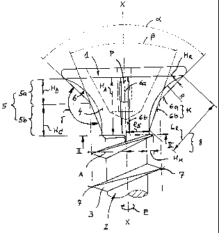
As the drawings show, a countersunk head screw
according to the invention has a head 1, a shank 2 and
a thread 3 extending at least partly over the shank 2.
The head 1 has a bearing surface 4 narrowing in the
direction of the shank 2. In addition, the head 1 has a
basic contour 5 which converges at a first angle a in a
first head section 5a remote from the shank 2 and at a
second, smaller angle a in a second head section 5b
facing the shank 2. In this case, the first angle a can
preferably be about 90 and the second angle 0 can
preferably be about 40 to 60 . This achieves the
effect that, despite a relatively narrow shape of the
head 1, there is sufficient space in the head 1 for a
cross recess (not designated in any more detail and
depicted in fig. 1 by broken lines) for the engagement
of a screwdriver.
Friction ribs 6, which extend over the two head
sections 5a, 5b, are arranged in the region of the
bearing surface 4. With their outer edges K, the
friction ribs 6 essentially follow the converging basic
contour 5 of the head 1. As a result, in each case a
first edge section 6a, lying in the region of the first
head section 5a, and a second edge section 6b, lying in
the region of the second head section 5b, of the outer
edges K of the friction ribs 6 enclose an obtuse angle y
with one another, which promotes easy axial penetration
of the screw into the material. The bearing surface 4
is set back radially in the direction of the shank 2
CA 02368906 2001-10-05
- 4 -
relative to the converging basic contour 5 of the head
1, as a result of which the material displacement is
minimized when the screw is being screwed in. In the
process, the presence=of the friction ribs 6 ensures a
high planar moment of inertia of the cross section of
the head 1 and thus the requisite torsional strength of
the screw.
In the embodiment shown, four friction ribs 6 are
provided, but more than or less than four may be
provided, for example three, six, eight or more. The
desired effect occurring when the countersunk head
screw according to the invention is being screwed in
can be set gradually and thus adapted to the material
by the number and design of the friction ribs 6.
With regard to its axial length HB, the first head
section 5a, in which the first edge section 6a of the
friction ribs 6 are arranged, should not be greater
than about 60 percent of an axial length HA of the
bearing surface 4. Likewise, with regard to its axial
length Hc, the second head section 5b, in which the
second edge section 6b of the friction ribs 6 is
arranged, should also not be greater than about 60
percent of an axial length HA of the bearing surface 4.
By such matching of the axial lengths HH, Hc of the
individual edge sections 6a, 6b of the bearing surface
4 to one another and to the entire axial length HA of
the bearing surface 4, a differentiated screw-in
behavior can advantageously be achieved, depending on
how far a countersunk head screw according to the
invention has already been screwed in.
As shown, the friction ribs 6, with regard to
their longitudinal extent LR, may run on generating
lines of the bearing surface 4, the projection P of
which falls onto a section, running through the head 1,
of the screw longitudinal axis X-X of the screw
according to the invention. In this way, the friction
effect which the ribs 6 exert on the material is
especially large.
CA 02368906 2001-10-05
- 5 -
The thread 3 has a thread edge 7 which, in a main
region, runs in the form of a helical line at a
constant distance (outer radius A of the thread 3). from
a section, running through the shank 2, of the screw
longitudinal axis X-X. In this case, the thread edge 7
may have a decreasing height HK in an end region 8 of
the thread 3 facing the head 1.
The first edge section 6a of the friction ribs 6,
in each case in an optimum arrangement with regard to
the friction ribs 6 coming into effect - as seen in the
bottom view or in the sectional representation shown in
fig. 2 - may extend in an annular region which is
defined on the outside approximately by the outer
radius Rx of the head 1 and on the inside approximately
by the outer radius A.
The second edge-section 6b of the friction ribs 6,
in each case in an optimum arrangement with regard to
the friction ribs 6 coming into effect - as seen in the
bottom view or in the sectional representation shown in
fig. 2 - may extend in an. annular region which is
defined on the outside approximately by the outer
radius A of the thread 3 and on the inside
approximately by the outer radius RS of the shank 2 at
the transition to the second head region 5b.
As a result, the vertex of the obtuse angle y
between the two edge sections 6a, 6b of the friction
ribs 6 lies in each case approximately on the outer
radius A of the thread 3.
In addition, it is advantageous in this case if
the bearing surface 4 is set back relative to the basic
contour 5 of the head 1 over the longitudinal extent LR
of the friction ribs 6 by a variable height HR defined
in particular by an arc of a circle having the radius
R. In this way, for example, as shown, the height HR of
the outer edges K of the friction ribs 6 over the
longitudinal extent LR of the friction ribs 6 increases
- starting from a value of zero relative to the bearing
surface 4 - at least in regions of the first head
section 5a and decreases at least in regions of the
CA 02368906 2001-10-05
- 6 -
second head section Sb in order to end again at a value
of zero relative to the bearing surface 4. In this
case, a maximum value of the height HR of the friction
ribs 6 relative to the bearing surface 4, in particular
at an outer radius RK of the head 1 of about 4 to 5 mm,
may preferably be about 0.3 to 0.7 mm.
The friction ribs 6 are optimally designed if, as
the drawing illustrates, they each have two side faces
6c, 6d which are designed in particular to be
symmetrical to one another and are each of convex shape
in each of the head sections 5a, 5b (fig. 2). In this
case, due to the symmetrical design of the friction
ribs 6, approximately the same effect occurs both when
screwing in the screw-in direction E and when
unscrewing the countersunk head screw according to the
invention against the screw-in direction E.
The strength-stabilizing effect of the friction
ribs 6 is influenced in a positive manner especially
when, as likewise shown, the outer edges K of the
friction ribs 6 are formed by edge surfaces (width B),
adjoining which are the side faces 6c, 6d. In this
case, the width B of the edge surfaces, in particular
at the outer radius RK, already mentioned by way of
example, of the head 1 of about 4 to 5 mm, may
advantageously be about 0.3 mm to 0.7 mm.
The invention is not restricted to the exemplary
embodiment described above, but also includes all the
embodiments having the same effect within the scope of
the invention. For example, the number, shape and
arrangement of the friction ribs 6 may differ from the
embodiment described. Thus, it may be appropriate for
the friction ribs 6, with regard to their longitudinal
extent LR, not to run as shown on generating lines of
the bearing surface 4, the projection P of which falls
onto a section, running through the head 1, of the
screw longitudinal axis X-X of the screw according to
the invention, but rather to lie (like the thread 3) on
a helical path running at least partly in the
circumferential direction.
CA 02368906 2001-10-05
- 7 -
It may also be advantageous if, as additionally
shown in fig. 3, at least some friction ribs 6, in
particular in their first edge section 6a, project
outward (as viewed from the shank 2) relative to the
basic contour 5 (converging as described, and indicated
in fig. 3 by a broken line) of the head 1 by an
oversize M formed, for example, by radiusing. As a
result, a braking effect occurs in the last screw-in
region of the countersunk head screw according to the
invention, a factor which may be of importance, in
particular in the case of short screws, such as screws
for fittings for example, when using mechanical
screwdrivers, since this prevents the screws from
turning, that is to say from turning on the spot,
without penetrating deeper into the material, once they
have been screwed in completely or almost completely,
and prevents the thread turns formed or cut in the
material from being destroyed. In this case, the
oversize M of the edge section 6a may be advantageously
selected such that it is only small, so that, after the
screwing-in, it is virtually pressed flat by the
surface pressure with the material into which the screw
is screwed.
The bearing surface 4 may also be set back
relative to the basic contour 5 of the head 1 over the
longitudinal extent LR of the friction ribs 6 in a
different way from that shown. An arc of an ellipse, a
parabola or a biconical contour (like that of the edge
sections 6a, 6b, but with appropriately different
convergence angles) may also take the place of the arc
of a circle (fig. 1)_
Furthermore, the invention is not restricted to
the combination of features defined in claim 1, but may
also be defined by any other desired combination of all
the individual features disclosed in their entirety.
This means that, in principle, virtually any individual
feature of claim 1 may be omitted or be replaced by at
least one feature disclosed elsewhere in the
application. In this respect, claim 1 is to be
CA 02368906 2001-10-05
- 8 -
understood merely as a first attempt at defining the
invention.
CA 02368906 2001-10-05
- 9 -
List of designations
1 Head
2 Shank
3 Thread
4 Bearing surface of 1
5 Basic contour of 1
5a First head section 1 (angle a)
5b Second head section 1 (angle 10 6 Friction rib
6a First edge section of K
6b Second edge section of K
6c, 6d Side faces of 6
7 Thread edge' of 3
8 End region of 3
A Outer radius of 3 (distance from 7 to X-X)
B Width of K
E Screw-in direction
HA Axial length of 4
HB Axial length of 5a
HC Axial length of 5b
HK Height of 7
HR Height of 6
K Outer edge of 6
rIR Longitudinal extent of 6
M Oversize of 6a
P Projection of 6
R Radius
Rx Outer radius of 1
Rs Radius of 2 at 5b
X-X Screw*longitudinal axis (through 1 and 2)
a Convergence angle of 5a
0 Convergence angle of 5b
y Angle between 6a and 6b