Note : Les descriptions sont présentées dans la langue officielle dans laquelle elles ont été soumises.
CA 02371582 2002-04-15
F&K 758-02-05
- Page 2 -
APPARATUS AND METHOD FOR CLEARING TRASH FROM FURROW
OPENER PATH
This invention is in the field of agricultural seeding equipment, and in
particular devices
for clearing trash from the ground surface to permit effective working of the
ground such
as seeding, fertilizing, and the like.
BACKGROUND
Tillage has been much reduced in modem agriculture in order to reduce costs,
conserve
moisture, and so forth. Seeding without tillage, or no-till seeding, has
become common
and preferred by many for crops such as grains, oilseeds, and pulses grown on
the prairies
of North America. These crops typically are grown in narrow rows, from 6 to 12
inches
apart.
Both disc and hoe type furrow openers are popular for no-till seeding as each
have their
own advantages. The performance of both disc and hoe types is best where crop
residue
such as straw and chaff, commonly referred to as trash, is light and evenly
spread. Where
trash is heavy, the disc may ride out of the ground. The discs can also push
straws into
the ground, a common problem called "hair-pinning". Hoe type openers often
gather
straw between them as they proceed along the field, causing plugging.
CA 02371582 2002-04-15
F&K 758-02-05
- Page 3 -
Modern furrow openers also commonly include depth control wheels that maintain
a
constant depth of penetration into the soil, providing proper seed depth for
optimum
germination and growth. Heavy trash can interfere with proper operation of
these depth
control wheels, since ideally they should run on the ground, or over a thin,
preferably
consistent, layer of trash so that the proper depth is maintained. Where trash
is thick and
uneven, the depth control wheel rides up and over the trash, drawing the
furrow opener
out of the ground and reducing seed depth to less than optimum, often in fact
leaving
seed on top of the ground.
Prior art has been addressed to devices for clearing trash from the path of a
furrow opener
to improve performance. United States Patent Numbers 4,785,890 to Martin,
5,346,020
to Bassett, 5,497,836 to Groff, and 5,878,678 to Stephens et al. disclose
trash clearing
apparatuses that include a pair of spoked or toothed trash clearing finger
wheels in a V
orientation in front of a furrow opener, such that the centers of the finger
wheels are
substantially located on a line parallel to the operating travel direction.
The finger wheels
clear trash in each direction from in front of the opener. Where such V
oriented finger
wheels are used in a narrow row spacing, with the furrow openers close
together, the
trash thrown away from the path by one of the finger wheels of the V apparatus
is thrown
against trash being thrown the opposite way by the opposite finger wheels of
the adjacent
V apparatus. The trash is thus not thrown clear since the two streams of trash
meet.
CA 02371582 2002-04-15
F&K 758-02-05
- Page 4 -
United States Patent Number 5,970,892 to Wendling et al. shows a single
similar wheel,
essentially one half of the V apparatus of the `678 patent to Stephens et al.
The single
wheel clears sufficient area to improve the performance of the disc. The
clearing wheel
is oriented to throw trash to the side of the row opposite the depth control
wheel, and
does not therefore clear trash from the path of the depth control wheel.
Trash clearing finger wheels are well known in a variety of types, as
disclosed for
example in United States Patent Numbers 5,346,020 to Bassett, 5,497,836 to
Groff, and
5,878,678 to Stephens et al.
These finger wheel clearing apparatuses should be maintained in proper
relation to the
ground without entering the ground and thereby increasing draft and stress on
the
apparatus, as well as causing excessive soil to be thrown with the trash.
SUMMARY OF THE INVENTION
It is the object of the present invention to provide an improved apparatus for
clearing
trash from a furrow opener path that is suitable for narrow row spacings. It
is a further
object of the invention to provide such an apparatus that can incorporate a
furrow
opening disc for applying agricultural product.
It is a further object of the invention to provide a paired row seeding
implement where
CA 02371582 2002-04-15
F&K 758-02-05
- Page 5 -
such a trash clearing apparatus clears trash from the path of two furrow
openers.
It is a further object of the invention to provide an improved method of
clearing trash
suitable for use with narrow row spacings.
The invention provides, in one aspect, an apparatus for clearing trash from a
furrow
opener path, the trash clearing apparatus adapted for attachment to an
implement for
movement along the ground in an operating travel direction ahead of a furrow
opener.
The apparatus comprises a front finger wheel rotatably mounted to the
apparatus and
oriented to move trash from a first path to a first side of the apparatus and
a rear finger
wheel rotatably mounted to the apparatus behind the front finger wheel and
oriented to
move trash from a second path to an opposite second side of the apparatus. The
front and
rear finger wheels are mounted such that the first and second paths are
adjacent to each
other, and such that the separation along the operating travel direction
between the front
and rear finger wheels is such that a first trash stream thrown by the front
finger wheel
does not meet a second trash stream thrown by the rear finger wheel of an
adjacent trash
clearing apparatus. A depth control wheel is rotatably mounted to the
apparatus such that
the depth control wheel rolls along the ground on the first path cleared by
the front finger
wheel. The depth control wheel is operative to maintain bottom edges of the
front and
rear finger wheels at a substantially constant vertical position relative to
the ground. An
adjusting mechanism is operative to adjust a vertical position of the depth
control wheel
with respect to at least one of the front and rear finger wheels.
CA 02371582 2002-04-15
F&K 758-02-05
- Page 6 -
The front finger wheel is typically rotatably mounted to the apparatus about a
first axis,
the first axis oriented at a first angle to the operating travel direction
such that a leading
side of the front finger wheel is ahead of a trailing side, and at a first
angle from the
horizontal such that the leading side is below the trailing side thereof
whereby trash
moved from a first path by the front finger wheel moves to a first side of the
apparatus.
Similarly the rear finger wheel is typically rotatably mounted to the
apparatus behind the
front finger wheel about a second axis, the second axis oriented at a second
angle to the
operating travel direction such that a leading side of the rear finger wheel
is ahead of a
trailing side , and at a second angle from the horizontal such that the
leading side is below
the trailing side thereof whereby trash moved from a second path by the rear
finger wheel
moves to an opposite second side of the apparatus.
In a second aspect the invention provides A paired row seeding implement
attachable to a
towing vehicle for movement along the ground in an operating travel direction,
the
implement comprising: a trash clearing apparatus attached to the implement,
the
apparatus comprising a front finger wheel rotatably mounted to the and
oriented to move
trash from a first path to a first side of the apparatus, a rear finger wheel
rotatably
mounted to the apparatus behind the front finger wheel and oriented to move
trash from a
second path to an opposite second side of the apparatus, wherein the front and
rear finger
wheels are mounted such that the first and second paths are adjacent to each
other and
such that the separation along the operating travel direction between the
front and rear
CA 02371582 2002-04-15
F&K 758-02-05
- Page 7 -
finger wheels is such that a first trash stream thrown by the front finger
wheel does not
meet a second trash stream thrown by the rear finger wheel of an adjacent
trash clearing
apparatus, a depth control wheel rotatably mounted to the apparatus such that
the depth
control wheel rolls along the ground on the first path cleared by the front
finger wheel,
the depth control wheel operative to maintain bottom edges of the front and
rear finger
wheels at a substantially constant vertical position relative to the ground
by; and an
adjusting mechanism operative to adjust a vertical position of the depth
control wheel
with respect to at least one of the front and rear finger wheels. A first
furrow opening
tool is attached to the implement behind the trash clearing apparatus and
oriented to
follow the first path, and a second furrow opening tool is attached to the
implement
behind the trash clearing apparatus and oriented to follow the second path. A
furrow
depth control device mounted at a fixed vertical position relative to at least
one furrow
opening tool, and oriented to move along the ground between the first and
second furrow
opening tools and maintain the first and second furrow opening tools at a
substantially
constant vertical position with respect to the ground.
The apparatus clears two closely adjacent paths, with little trash left
between the paths.
A furrow opening implement can incorporate a following furrow opener in each
path,
with a depth control wheel running on the cleared ground of the paths. One
depth control
device, such as a wheel or skid plate can control the depth of two adjacent
openers.
CA 02371582 2002-04-15
F&K 758-02-05
- Page 8 -
The invention also provides, in a third aspect, a method of clearing trash
from a plurality
of adjacent paired furrow opener paths of a furrow opening implement, each
paired
furrow opener path comprising a first path and an adjacent second path. The
method
comprises with a first front finger wheel, throwing first trash from the first
path towards a
first side of the paired furrow opener path, relative to an operating travel
direction of the
implement; after the first trash has substantially landed on the ground, with
a rear finger
wheel throwing second trash from the second path towards a second side of the
paired
furrow opener path, relative to the operating travel direction of the
implement, and on top
of first trash thrown by an adjacent second front finger wheel; maintaining
bottom edges
of the front and rear finger wheels at a substantially constant vertical
position relative to
the ground with a depth control wheel oriented to roll along the ground on the
first path
cleared by the front finger wheel.
The front finger wheel moves trash to one side, and the rear finger wheel
moves adjacent
trash to the opposite side. In a narrow row spacing, a plurality of front
finger wheels
moves first trash from a first path in one direction, while the following
plurality of rear
finger wheels moves second trash in the opposite direction. The first trash
has landed on
the ground by the time the second trash is moved so that the second trash
lands on top of
the first trash. Conventionally, the trash is moved both directions at once by
a V oriented
pair of finger wheels such that the trash moving in one direction hits the
trash moving in
the opposite direction, resulting in a poor spread, and spill back onto the
cleared path.
CA 02371582 2002-04-15
F&K 758-02-05
- Page 9 -
The bottom edges of the front and rear finger wheels may be maintained at a
substantially
constant vertical position relative to the ground by one depth control wheel
rolling along
the ground on the first path cleared by the front finger wheel, and beside or
somewhat
ahead of the rear finger wheel. The depth control wheel runs on cleared ground
of the
first path and so maintains the proper relation of the apparatus with the
ground, as it does
not ride up and down over trash accumulations. Depending on the attachment to
the
implement, as the apparatus moves along the ground the front and rear finger
wheels may
move somewhat relative to the ground, however such a system will often provide
satisfactory service.
More precise vertical positioning of the front and rear finger wheels may be
provided.
The front and rear finger wheels may be oriented such that bottom edges
thereof are on a
horizontal plane as they move up and down with the terrain and a depth control
wheel is
located between them in a good location to maintain the finger wheels at the
proper
vertical location relative to the ground.
Alternatively a depth control wheel may be provided adjacent to each finger
wheel to
control the vertical position thereof. Both depth control wheels run on the
cleared ground
of the first path, and so are not moving up and down over uncleared trash.
More precise control of the vertical position of the finger wheels reduces
excessive stress
and soil throw.
CA 02371582 2002-04-15
F&K 758-02-05
- Page 10 -
The addition of a furrow opening disc closely behind the front finger wheel
provides the
advantage, well known in the art, of cutting straws that are held under
tension by the
finger wheel as it pulls the trash away from the path of the furrow opening
disc.
Agricultural product such as seed or fertilizer can also be placed in the
soil.
DESCRIPTION OF THE DRAWINGS:
While the invention is claimed in the concluding portions hereof, preferred
embodiments
are provided in the accompanying detailed description which may be best
understood in
conjunction with the accompanying diagrams where like parts in each of the
several
diagrams are labeled with like numbers, and where:
Fig. 1 is a side view of an embodiment of the invention;
Fig. 2 is a top view of the embodiment of Fig. 1;
Fig. 3 is a schematic top view of the embodiment of Fig. I showing the
orientation of the
axes of the rotating parts relative to the operating travel direction;
Fig. 4 is a schematic rear view of the embodiment of Fig. I showing the
orientation of the
axes of the rotating parts relative to the horizontal;
CA 02371582 2002-04-15
F&K 758-02-05
- Page 11 -
Fig. 5 is a schematic side view showing the vertical relationship of the front
and rear
finger wheels, and furrow opening disc;
Fig. 6 is a schematic top view of a paired row seeding implement using the
embodiment
of Fig. I to clear trash from a pair of furrow opening tools;
Fig. 7 is a schematic side view of an alternate embodiment where the vertical
position of
the finger wheels is maintained by a depth control wheel on each finger wheel;
Fig. 8 is a schematic top view of the embodiment of Fig. 7;
Fig. 9 is a schematic side view of an alternate embodiment where the vertical
position of
the finger wheels is maintained by a single depth control wheel running
between the
finger wheels;
Fig. 10 is a side view of an alternate paired row seeding apparatus of the
invention;
Fig. 11 is top view of the apparatus of Fig. 10;
Fig. 12 is a schematic top view of a typical arrangement of a plurality of the
paired row
seeding apparatuses 300 on an implement.
CA 02371582 2002-04-15
F&K 758-02-05
- Page 12 -
DETAILED DESCRIPTION OF THE ILLUSTRATED EMBODIMENTS:
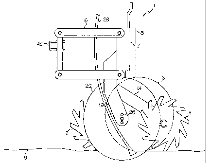
Figs. I and 2 illustrate an apparatus for clearing trash from a furrow opener
path. Figs. 3
- 5 illustrate the orientation of the various parts. The trash clearing
apparatus 1 is adapted
for attachment to an implement for movement along the ground in an operating
travel
direction T ahead of a furrow opener, or a pair of furrow openers. The
apparatus 1 is
conventionally mounted to a seeding implement frame 40. Down pressure is
applied to
the apparatus 1 by conventional springs, hydraulic cylinders, or the like.
The apparatus comprises a front finger wheel 2 rotatably mounted to the
apparatus 1 and
oriented to move trash from a first path P 1 to a first side S 1 of the
apparatus 1. A rear
finger wheel 4 is rotatably mounted to the apparatus 1 behind the front finger
wheel 2 and
is oriented to move trash from a second path P2 to an opposite second side S2
of the
apparatus 1. In the embodiments of Figs. I and 2 the front and rear finger
wheels 2, 4 are
mounted such that bottom edges thereof 2b, 4b are located substantially on a
horizontal
plane HP and such that the first and second paths P1, P2 are closely adjacent.
The
bottom edges 2b, 4b are maintained substantially on the horizontal plane HP as
the
apparatus I moves up and down in response to terrain variations as it moves
along the
ground by the action of the parallel bar linkage 6. The rear bar 7 of the
linkage 6 remains
substantially vertical as the apparatus I moves up and down, and the operating
parts of
the apparatus 1 are attached thereto as described below.
. _. _._,
CA 02371582 2002-04-15
F&K 758-02-05
- Page 13 -
As illustrated in Fig. 6, the separation along the operating travel direction
between the
front and rear finger wheels 2, 4 is such that a first trash stream TR1 thrown
by the front
finger wheel 2 does not meet a second trash stream TR2 thrown by the rear
finger wheel
4 of an adjacent trash clearing apparatus. For common implement travel speeds,
it is
contemplated that the separation should be 20 centimeters or more between
rotational
centers of the finger wheels 2, 4.
A depth control wheel 8 is rotatably mounted to the bottom of an adjusting
mechanism,
shown in the embodiment as a screw jack 5, fixed to rear bar 7, such that it
rolls along the
ground 9 ahead of the rear finger wheel 4 on the first path P 1 cleared by the
front finger
wheel 2. The vertical position of the depth control wheel 8 is adjustable
relative to a
vertical position of the horizontal plane HP by adjustment of screw jack 5.
The handle of
the screw jack 5 is conveniently located on the top side of the apparatus I so
that
adjustment may be inade with reduced bending or crawling under the implement.
The front finger wheel 2 is rotatably mounted to a front arm 10, fixed to the
rear bar 7,
about a first axis Al oriented at a first angle N 1 to the operating travel
direction T such
that a leading side 11 of the front finger wheel 2 is ahead of a trailing side
12 and at a
first angle M 1 from the horizontal such that the leading side 11 is below the
trailing side
12 thereof whereby trash moved from the first path P 1 by the front finger
wheel 2 moves
to a first side S 1 of the apparatus 1.
CA 02371582 2002-04-15
F&K 758-02-05
- Page 14 -
Similarly the rear finger wheel 2 is rotatably mounted to a rear arm 14, fixed
to the rear
bar 7, about a second axis A2 oriented at a second angle N2 to the operating
travel
direction T such that a leading side 15 of the rear finger wheel 4 is ahead of
a trailing side
16, and at a second angle M2 from the horizontal such that the leading side 15
is below
the trailing side 16 whereby trash moved from the second path P2 by the rear
finger
wheel 4 moves to the opposite second side S2 of the apparatus 1. The
orientation of the
axes Al, A2 is illustrated in Figs. 3 and 4.
The distance trash is thrown by the rear finger wheel 4 may be reduced by
reducing the
angle M2 of the second axis A2 to zero, or even tilting the axis A2 back the
opposite
way. The throwing distance can be varied so that trash stream TR2 thrown by
the rear
finger wheel 4, as indicated in Fig. 6, does not land on the cleared path P 1
of the adjacent
apparatus. The trash stream TR1 thrown by the front finger wheel 2 is blocked
by the
disc 20, and so the throwing distance for this stream TR1 is not as critical
as that for
stream TR2 where there is nothing to block the stream. The finger wheel angles
N1, N2,
M 1, and M2 can be adj usted for the particular conditions that are
encountered.
A furrow opening disc 20 is rotatably mounted to disc arm 19, fixed to rear
bar 7, about a
disc axis DA oriented at a disc angle N3 to the operating travel direction T
such that a
leading side 21 of the disc 20 corresponds to the leading side 11 of the front
finger wheel
2. The disc angle N3 is sufficiently large to allow the disc 20 to open a
furrow as is well
CA 02371582 2002-04-15
F&K 758-02-05
- Page 15 -
known in the art. The disc 20 is located between the front and rear finger
wheels 2, 4
such that a front edge 23 of the disc 20 is located ahead of a front edge 25
of the depth
control wheel 8 and in proximity to the trailing side 12 of the front finger
wheel 2 such
that straws contacted by the disc 20 as it cuts into the ground 9 are at
substantially the
same time contacted by the front finger wheel 2, thereby placing tension on
the straws
and facilitating cutting of the straws by the disc 20. This orientation of a
trash clearing
finger wheel and furrow opening disc is known in the present art.
The bottom edge 20b of the disc 20 is located at a fixed distance X below the
horizontal
plane HP, as illustrated in Fig. 5. The distance X can be varied by mounting
the furrow
opening disc 20 in various holes 26 in disc arm 19, so that the furrow depth
may be
varied. The screw jack 5 is adjusted so that the horizontal plane HP is
substantially at
ground level, such that the finger wheels 2, 4 move trash but not soil. The
furrow depth
is set by adjusting the distance X with holes 26.
As is common in the field, the disc axis DA is horizontal in the illustrated
embodiment,
as seen in Fig. 4. Alternately, it is contemplated that the disc axis DA could
be at an
angle to the horizontal such that the disc is inclined from the vertical as
well as the
operating travel direction, providing a double angled disc such as the
BartonTM disc
opener, manufactured by Flexicoil Ltd. of Saskatoon, Canada.
CA 02371582 2002-04-15
F&K 758-02-05
- Page 16 -
The depth control wheel 8 is rotatably mounted about a wheel axis WA oriented
substantially parallel to, and rearward of, the disc axis DA as seen in Fig.
3. A front
portion of the trailing side 28 of the depth control wheel 8 is closely
adjacent to or
touching a portion of the leading side 21 of the furrow opening disc 20 that
is rearward of
the front edge 23 of the furrow opening disc 20. The depth control wheel 8
runs along
the ground 9 over soil moved by the leading side 21 and prevents soil throw.
The depth
control wheel 8 also cleans the furrow opening disc 20 as it comes out of the
ground 9.
The front edge 27 of the rear finger wheel 4 is located in proximity to the
trailing side 22
of the disc 20. The paths P1, P2 are thus kept closely adjacent such that
minimal trash is
left between them.
The apparatus may conveniently include a delivery tube 29 to deliver
agricultural product
to the furrow created by disc 20. The furrow can be conventionally closed if
desired, or
will be covered by following furrow openers in a paired row seeding implement.
A paired row seeding implement 30 is schematically illustrated in Fig. 6 to
show the
action of the trash clearing apparatuses 1 in the field, and to illustrate a
set up for a paired
row seeder where depth control wheels or skids for the furrow openers of the
seeder also
run on the cleared paths P 1, P2. Depth control is thus improved since the
depth control
wheels run on the ground and do not ride over trash.
CA 02371582 2002-04-15
F&K 758-02-05
- Page 17 -
A plurality of right and left trash clearing apparatuses I R, 1 L , and a
center apparatus I C
are mounted at the front of the implement 30. The front finger wheels 2 throw
first trash
stream TR1 from each first path towards a first side S 1 of each paired furrow
opener path
P1, P2, relative to an operating travel direction T of the implement. For the
right
apparatus 1 R, the first side S 1 is on the right, and for the left apparatus
1 L, the first side
S 1 is on the left.
After the first trash has landed on the ground, the rear finger wheel 4 throws
second trash
stream TR2 from each second path P2 towards the opposite second side S2 and on
top of
the first trash thrown by the front finger wheel 2 of an adjacent apparatus 1.
Thus it can be seen that trash flows smoothly as the implement passes. With
prior art
trash clearing apparatuses the finger wheels 2, 4 are substantially on the
same line
perpendicular to the travel direction T, such that first trash stream TR1 is
thrown against
the second trash stream TR2 such that the trash streams TR1, TR2 collide. This
is
especially problematic where a narrow row spacing is used.
The implement is shown with right and left apparatuses I R, 1 L in order to
balance side
draft as is known in the art. The center apparatus 1 C is required in the
center of the
implement to make the transition over from throwing one way with the front
finger wheel
2 to the other way.
CA 02371582 2002-04-15
F&K 758-02-05
- Page 18 -
A first furrow opener 31, including a depth control wheel 32 and a furrow
opening tool
33 which as illustrated is a disc but could also be a hoe opener. The furrow
opening tool
33 follows the first path P1 and is located toward the first side S 1 of the
trash clearing
apparatus 1 relative to the depth control wheel 32 such that the depth control
wheel 32
rolls on or adjacent to the second path P2, between the furrow opening tools
33 of the
first and second furrow openers 31, 34.
The second furrow opener 34 is oriented the opposite way, so that the furrow
opening
tool 33 follows the second path P2 and is located toward the second side S2 of
the trash
clearing apparatus relative to the depth control wheel 32 such that the depth
control wheel
32 rolls on or adjacent to the first path P2, between the furrow opening tools
33 of the
first and second furrow openers 31, 34.
The paired row furrow opening tools 33 are thus running on cleared ground at a
furrow
spacing FS of, for example 5 inches, and as well the depth control wheels 32
are also
running, as is preferred, on cleared ground between the furrow opening tools
33. Spacing
the apparatuses 1 at a spacing AS of 15 inches along the implement results in
a 10 inch
spacing between the adjacent paired seed rows. The effective seed row spacing
is 7.5
inches, which is desired by some farmers to achieve their preferred plant
density.
Alternatively seed could be placed through the furrow opening disc 20 and
fertilizer
through the furrow opening tools 33, to provide a 15 inch row spacing. The
apparatus I
also provides seed/fertilizer separation as required to prevent seed damage.
CA 02371582 2002-04-15
F&K 758-02-05
- Page 19 -
With the apparatus I and furrow opening tools 33 mounted separately on the
implement
30, each rides separately over obstacles in the field, such as stones.
An alternate apparatus 100 of the invention is schematically illustrated in
Figs. 7 and 8.
The bottom edges 102b, 104b of the front and rear finger wheels 102, 104 are
maintained
at a substantially constant vertical position relative to the ground as the
apparatus 100
moves up and down in response to terrain variations as it moves along the
ground by a
first depth control wheel 106 mounted to the apparatus 100 in a fixed vertical
position
relative to the front finger wheel 102 such that the first depth control wheel
106 rolls
along the ground ahead of the rear finger wheel 104 on the first path Pl'
cleared by the
front finger wheel 102, and by a second depth control wheel 108 mounted to the
apparatus 100 in a fixed vertical position relative to the rear finger wheel
104 such that
the second depth control wheel 108 rolls along the ground beside the rear
finger wheel
104 on the first path Pl'.
A first furrow opening tool, first disc 110, is mounted to the apparatus 100
adjacent to the
first depth control wheel 106 and in fixed vertical relation thereto so as to
follow the first
path P1', and a second furrow opening tool, second disc 112 is mounted to the
apparatus
100 adjacent to the second depth control wheel 108 and in fixed vertical
relation thereto
so as to also follow the first path P1' at a lateral distance from the first
disc 110. The
depth control wheel 106, 108 run on opposite sides of the respective discs
110, 112 so
CA 02371582 2002-04-15
F&K 758-02-05
- Page 20 -
that same may run on the cleared first path Pl'. The depth of the furrows made
by first
and second discs 1 10, 112 would be by mounting in one of a plurality of
holes, such as
holes 26 in Fig. 1.
A third furrow opening tool, third disc 114, is mounted to the apparatus 100
adjacent to a
third depth control wheel 116 and in fixed vertical relation thereto so as to
follow the
second path P2'. The third depth control wheel 116 rolls along the first or
second path
P1', P2' and controls the depth of the furrow made by the third disc 114.
The depth control wheels 106, 108, 116 can be connected to a screw jack 5 such
as
illustrated in Fig. I to allow easy adjustment of the vertical position of the
depth control
wheels. One or more of the furrow opening tools could be hoes rather than
discs.
The finger wheels 102, 104, discs 110, 112, 114, and depth control wheels 106,
108, 116
are mounted to a walking beam 120 to allow the apparatus 100 to follow ground
contours.
Fig. 9 illustrates an alternate apparatus 200 of the invention where the rear
firiger wheel
104 of Fig. 7 is moved ahead to a position generally beside the first depth
control wheel
106 and in fixed vertical relation thereto. First depth control wheel 106 then
controls the
vertical position of the front and rear finger wheels 102, 104. The vertical
control is not
as precise as that of the previously illustrated embodiments, however would
provide
CA 02371582 2002-04-15
F&K 758-02-05
- Page 21 -
satisfactory service in some conditions, such as on level ground. Second depth
control
wheel 108 would then adjust the depth of the second disc 112, rather than
requiring a
plurality of holes as in the apparatus 100 of Fig. 7.
Figs. 10 - 12 illustrate an alternative paired row seeding apparatus 300 of
the invention.
The trash clearing apparatus 301 is the same as that illustrated in Figs 1 and
2, however in
this embodiment, the parallel bar linkage 306 is attached to the implement
frame 340 at
the rear thereof instead at the front thereof as illustrated in Fig. 1. The
front bar 307
remains substantially vertical as the apparatus 301 moves up and down, thus
maintaining
the bottoms of the finger wheels 2, 4 on the horizontal plane HP.
A paired row seeding apparatus 310 is mounted to a second parallel linkage 312
mounted
to the implement frame 340 directly behind the trash clearing apparatus 301.
Furrow
opening tools, illustrated as discs 314, are rotatably mounted to the second
parallel
linkage 312 and oriented so as to follow in the cleared paths P1, P2 provided
by the trash
clearing apparatus 301. A single furrow depth control device, illustrated as
furrow depth
control wheel 316 is oriented to roll along the ground between the discs 314
and control
the depth of both discs 314. The wheel 316 runs on the both paths P 1 and P2
which are
closely spaced so that very little trash is left on the ground between them.
Spoked
closing wheels 318 are conventionally mounted to close the furrows made by the
discs
314, and seed or fertilizer is delivered to the furrows by tubes 320.
CA 02371582 2002-04-15
F&K 758-02-05
- Page 22 -
An alternate furrow depth control device is schematically illustrated in Fig.
13 as a skid
plate 322 with a turned up front end 324. The skid plate 322 follows the
ground in the
same manner as the wheel 316 and controls the depth of the furrow opening
tools, such as
discs 314.
Fig. 12 schematically illustrates the arrangement of a plurality of the paired
row seeding
apparatuses 300 on an implement. Similar to the configuration of Fig. 6, they
include a
right apparatus 300R, a left apparatus 300L, and a center apparatus 300C.
The foregoing is considered as illustrative only of the principles of the
invention.
Further, since numerous changes and modifications will readily occur to those
skilled in
the art, it is not desired to limit the invention to the exact construction
and operation
shown and described, and accordingly, all such suitable changes or
modifications in
structure or operation which may be resorted to are intended to fall within
the scope of
the claimed invention.